US8608616B2 - Clutch control device of hybrid vehicle - Google Patents
Clutch control device of hybrid vehicle Download PDFInfo
- Publication number
- US8608616B2 US8608616B2 US13/712,559 US201213712559A US8608616B2 US 8608616 B2 US8608616 B2 US 8608616B2 US 201213712559 A US201213712559 A US 201213712559A US 8608616 B2 US8608616 B2 US 8608616B2
- Authority
- US
- United States
- Prior art keywords
- clutch
- engagement
- control device
- control unit
- vehicle
- Prior art date
- Legal status (The legal status is an assumption and is not a legal conclusion. Google has not performed a legal analysis and makes no representation as to the accuracy of the status listed.)
- Expired - Fee Related
Links
Images


Classifications
-
- B—PERFORMING OPERATIONS; TRANSPORTING
- B60—VEHICLES IN GENERAL
- B60K—ARRANGEMENT OR MOUNTING OF PROPULSION UNITS OR OF TRANSMISSIONS IN VEHICLES; ARRANGEMENT OR MOUNTING OF PLURAL DIVERSE PRIME-MOVERS IN VEHICLES; AUXILIARY DRIVES FOR VEHICLES; INSTRUMENTATION OR DASHBOARDS FOR VEHICLES; ARRANGEMENTS IN CONNECTION WITH COOLING, AIR INTAKE, GAS EXHAUST OR FUEL SUPPLY OF PROPULSION UNITS IN VEHICLES
- B60K6/00—Arrangement or mounting of plural diverse prime-movers for mutual or common propulsion, e.g. hybrid propulsion systems comprising electric motors and internal combustion engines
- B60K6/20—Arrangement or mounting of plural diverse prime-movers for mutual or common propulsion, e.g. hybrid propulsion systems comprising electric motors and internal combustion engines the prime-movers consisting of electric motors and internal combustion engines, e.g. HEVs
- B60K6/42—Arrangement or mounting of plural diverse prime-movers for mutual or common propulsion, e.g. hybrid propulsion systems comprising electric motors and internal combustion engines the prime-movers consisting of electric motors and internal combustion engines, e.g. HEVs characterised by the architecture of the hybrid electric vehicle
- B60K6/44—Series-parallel type
- B60K6/442—Series-parallel switching type
-
- B—PERFORMING OPERATIONS; TRANSPORTING
- B60—VEHICLES IN GENERAL
- B60W—CONJOINT CONTROL OF VEHICLE SUB-UNITS OF DIFFERENT TYPE OR DIFFERENT FUNCTION; CONTROL SYSTEMS SPECIALLY ADAPTED FOR HYBRID VEHICLES; ROAD VEHICLE DRIVE CONTROL SYSTEMS FOR PURPOSES NOT RELATED TO THE CONTROL OF A PARTICULAR SUB-UNIT
- B60W20/00—Control systems specially adapted for hybrid vehicles
- B60W20/10—Controlling the power contribution of each of the prime movers to meet required power demand
-
- B—PERFORMING OPERATIONS; TRANSPORTING
- B60—VEHICLES IN GENERAL
- B60W—CONJOINT CONTROL OF VEHICLE SUB-UNITS OF DIFFERENT TYPE OR DIFFERENT FUNCTION; CONTROL SYSTEMS SPECIALLY ADAPTED FOR HYBRID VEHICLES; ROAD VEHICLE DRIVE CONTROL SYSTEMS FOR PURPOSES NOT RELATED TO THE CONTROL OF A PARTICULAR SUB-UNIT
- B60W10/00—Conjoint control of vehicle sub-units of different type or different function
- B60W10/02—Conjoint control of vehicle sub-units of different type or different function including control of driveline clutches
-
- F—MECHANICAL ENGINEERING; LIGHTING; HEATING; WEAPONS; BLASTING
- F16—ENGINEERING ELEMENTS AND UNITS; GENERAL MEASURES FOR PRODUCING AND MAINTAINING EFFECTIVE FUNCTIONING OF MACHINES OR INSTALLATIONS; THERMAL INSULATION IN GENERAL
- F16D—COUPLINGS FOR TRANSMITTING ROTATION; CLUTCHES; BRAKES
- F16D48/00—External control of clutches
- F16D48/06—Control by electric or electronic means, e.g. of fluid pressure
-
- B—PERFORMING OPERATIONS; TRANSPORTING
- B60—VEHICLES IN GENERAL
- B60W—CONJOINT CONTROL OF VEHICLE SUB-UNITS OF DIFFERENT TYPE OR DIFFERENT FUNCTION; CONTROL SYSTEMS SPECIALLY ADAPTED FOR HYBRID VEHICLES; ROAD VEHICLE DRIVE CONTROL SYSTEMS FOR PURPOSES NOT RELATED TO THE CONTROL OF A PARTICULAR SUB-UNIT
- B60W2510/00—Input parameters relating to a particular sub-units
- B60W2510/02—Clutches
- B60W2510/0241—Clutch slip, i.e. difference between input and output speeds
-
- B—PERFORMING OPERATIONS; TRANSPORTING
- B60—VEHICLES IN GENERAL
- B60Y—INDEXING SCHEME RELATING TO ASPECTS CROSS-CUTTING VEHICLE TECHNOLOGY
- B60Y2300/00—Purposes or special features of road vehicle drive control systems
- B60Y2300/60—Control of electric machines, e.g. problems related to electric motors or generators
- B60Y2300/66—Control for gear shift synchronisation
-
- B—PERFORMING OPERATIONS; TRANSPORTING
- B60—VEHICLES IN GENERAL
- B60Y—INDEXING SCHEME RELATING TO ASPECTS CROSS-CUTTING VEHICLE TECHNOLOGY
- B60Y2300/00—Purposes or special features of road vehicle drive control systems
- B60Y2300/70—Control of gearings
- B60Y2300/73—Synchronisation of shaft speeds
-
- F—MECHANICAL ENGINEERING; LIGHTING; HEATING; WEAPONS; BLASTING
- F16—ENGINEERING ELEMENTS AND UNITS; GENERAL MEASURES FOR PRODUCING AND MAINTAINING EFFECTIVE FUNCTIONING OF MACHINES OR INSTALLATIONS; THERMAL INSULATION IN GENERAL
- F16D—COUPLINGS FOR TRANSMITTING ROTATION; CLUTCHES; BRAKES
- F16D2500/00—External control of clutches by electric or electronic means
- F16D2500/10—System to be controlled
- F16D2500/106—Engine
- F16D2500/1066—Hybrid
-
- F—MECHANICAL ENGINEERING; LIGHTING; HEATING; WEAPONS; BLASTING
- F16—ENGINEERING ELEMENTS AND UNITS; GENERAL MEASURES FOR PRODUCING AND MAINTAINING EFFECTIVE FUNCTIONING OF MACHINES OR INSTALLATIONS; THERMAL INSULATION IN GENERAL
- F16D—COUPLINGS FOR TRANSMITTING ROTATION; CLUTCHES; BRAKES
- F16D2500/00—External control of clutches by electric or electronic means
- F16D2500/30—Signal inputs
- F16D2500/304—Signal inputs from the clutch
- F16D2500/30401—On-off signal indicating the engage or disengaged position of the clutch
-
- F—MECHANICAL ENGINEERING; LIGHTING; HEATING; WEAPONS; BLASTING
- F16—ENGINEERING ELEMENTS AND UNITS; GENERAL MEASURES FOR PRODUCING AND MAINTAINING EFFECTIVE FUNCTIONING OF MACHINES OR INSTALLATIONS; THERMAL INSULATION IN GENERAL
- F16D—COUPLINGS FOR TRANSMITTING ROTATION; CLUTCHES; BRAKES
- F16D2500/00—External control of clutches by electric or electronic means
- F16D2500/30—Signal inputs
- F16D2500/304—Signal inputs from the clutch
- F16D2500/30406—Clutch slip
-
- F—MECHANICAL ENGINEERING; LIGHTING; HEATING; WEAPONS; BLASTING
- F16—ENGINEERING ELEMENTS AND UNITS; GENERAL MEASURES FOR PRODUCING AND MAINTAINING EFFECTIVE FUNCTIONING OF MACHINES OR INSTALLATIONS; THERMAL INSULATION IN GENERAL
- F16D—COUPLINGS FOR TRANSMITTING ROTATION; CLUTCHES; BRAKES
- F16D2500/00—External control of clutches by electric or electronic means
- F16D2500/30—Signal inputs
- F16D2500/304—Signal inputs from the clutch
- F16D2500/3041—Signal inputs from the clutch from the input shaft
- F16D2500/30415—Speed of the input shaft
-
- F—MECHANICAL ENGINEERING; LIGHTING; HEATING; WEAPONS; BLASTING
- F16—ENGINEERING ELEMENTS AND UNITS; GENERAL MEASURES FOR PRODUCING AND MAINTAINING EFFECTIVE FUNCTIONING OF MACHINES OR INSTALLATIONS; THERMAL INSULATION IN GENERAL
- F16D—COUPLINGS FOR TRANSMITTING ROTATION; CLUTCHES; BRAKES
- F16D2500/00—External control of clutches by electric or electronic means
- F16D2500/30—Signal inputs
- F16D2500/304—Signal inputs from the clutch
- F16D2500/3042—Signal inputs from the clutch from the output shaft
- F16D2500/30426—Speed of the output shaft
-
- F—MECHANICAL ENGINEERING; LIGHTING; HEATING; WEAPONS; BLASTING
- F16—ENGINEERING ELEMENTS AND UNITS; GENERAL MEASURES FOR PRODUCING AND MAINTAINING EFFECTIVE FUNCTIONING OF MACHINES OR INSTALLATIONS; THERMAL INSULATION IN GENERAL
- F16D—COUPLINGS FOR TRANSMITTING ROTATION; CLUTCHES; BRAKES
- F16D2500/00—External control of clutches by electric or electronic means
- F16D2500/30—Signal inputs
- F16D2500/316—Other signal inputs not covered by the groups above
- F16D2500/3166—Detection of an elapsed period of time
-
- Y—GENERAL TAGGING OF NEW TECHNOLOGICAL DEVELOPMENTS; GENERAL TAGGING OF CROSS-SECTIONAL TECHNOLOGIES SPANNING OVER SEVERAL SECTIONS OF THE IPC; TECHNICAL SUBJECTS COVERED BY FORMER USPC CROSS-REFERENCE ART COLLECTIONS [XRACs] AND DIGESTS
- Y02—TECHNOLOGIES OR APPLICATIONS FOR MITIGATION OR ADAPTATION AGAINST CLIMATE CHANGE
- Y02T—CLIMATE CHANGE MITIGATION TECHNOLOGIES RELATED TO TRANSPORTATION
- Y02T10/00—Road transport of goods or passengers
- Y02T10/60—Other road transportation technologies with climate change mitigation effect
- Y02T10/62—Hybrid vehicles
Definitions
- This invention relates to a clutch control device of a hybrid vehicle.
- hybrid vehicles which are allowed to run by a combination of the driving force of a motor and the driving force of an engine, have been developed, and put to increased practical use.
- the hybrid vehicles are, for example, those adopting the series method in which the vehicle is run by the driving force of the motor, and the engine is used as a power source for an electric generator, and those relying on the parallel method in which the vehicle is run by the driving forces of both of the engine and the motor (or the driving force of the engine alone).
- a clutch provided in a power transmission mechanism is disengaged or engaged to switch among the paths of power transmission. That is, the motor is connected to driving wheels, and the engine is connected to the driving wheels via the clutch.
- the clutch In the EV travel mode and the series travel mode, the clutch remains disengaged, and only power from the motor is transmitted to the driving wheels.
- the clutch In the parallel travel mode, the clutch is in an engaged state, and the power of the engine and the power of the motor are transmitted to the driving wheels.
- the clutch control device described in Patent Document 1 is a clutch control device for controlling a clutch, the clutch comprising a pair of engaging members provided in a power transmission path of a vehicle and relatively moving in an axial direction to engage with or disengage from each other; and a driving means for exerting a driving force on at least one of the pair of engaging members to direct it toward the other engaging member, according to a command value inputted to the driving means, wherein the clutch control device exercises engagement control for inputting into the driving means a predetermined command value preset as a command value which brings the pair of engaging members into a completely engaged state and, if the pair of engaging members are not judged to be in the completely engaged state after the predetermined command value has been inputted to the driving means in the engagement control, the clutch control device changes the command value to a value corresponding to a greater driving force than a driving force corresponding to the predetermined command value.
- this clutch control device when the engaging members of the clutch are judged not to have been engaged in the clutch engagement attempts even in the presence of a temporary inclination or snagging, control is exercised so as to increase the driving force exerted on the engaging members, thereby engaging the clutch.
- the clutch When a hydraulic clutch is used as the clutch, moreover, the clutch may be minimally engaged in a state where the oil temperature of the clutch is low, such as under low temperature conditions. Thus, a clutch-nonengageable status due to a temporary factor may be present. In such a case, the clutch can be engaged, but it is determined that its engagement is impossible. As a result, there is a possibility that the clutch cannot be engaged. Particularly, a vehicle, in which the travel mode can be switched from the series travel mode to the parallel travel mode as stated earlier, has many opportunities to carry out the engagement of the clutch. If a determination of whether the clutch is engaged or disengaged cannot be made correctly in such a vehicle, the vehicle cannot run in a proper travel mode, although the clutch is engageable.
- the present invention aims at solving the problems of the conventional technologies mentioned above. It is an object of this invention to provide a clutch control device of a hybrid vehicle which can engage a clutch in the case of the inability to engage the clutch due to a temporary factor, such as difficulty in engaging the clutch in a state where the oil temperature of the clutch is low, for example, under low temperature conditions; and which can make a simplified and accurate determination of whether the engaging members of the clutch have been successfully engaged or not.
- the clutch control device of a hybrid vehicle is a clutch control device for exercising disengagement and engagement control of a clutch in a hybrid vehicle, the hybrid vehicle having formed therein a driving force transmission path for transmitting a driving force from an engine to driving wheels via the clutch, and a rotating force transmission path in which an electric motor is connected between the clutch and the driving wheels to transmit a rotating force of the electric motor to the driving wheels, wherein the clutch comprises a first clutch plate to which the driving force from the engine is inputted, and a second clutch plate engaging the first clutch plate to form the driving force transmission path, the second clutch plate is configured to be synchronized with rotation of the electric motor, and the clutch control device has determination means which determines that engagement of the clutch has been accomplished, on condition that a difference between rotational numbers of the first clutch plate and the second clutch plate at a predetermined engaging time after start of the engagement of the clutch is equal to or smaller than a predetermined value, when the clutch control device performs the disengagement and engagement control of the clutch so as to switch from a first travel mode
- the clutch engagement takes place at the predetermined engaging time, moreover, the clutch can be engaged in the case of a clutch engagement failure due to a temporary factor, such as difficulty of clutch engagement at a low oil temperature of the clutch, for example, under low temperature conditions.
- a preferred embodiment of the present invention is that when the clutch control device determines that the engagement of the clutch has not been accomplished, the clutch control device starts engagement of the clutch repeatedly, and corrects the predetermined engaging time according to count of how many times it has been determined that the engagement of the clutch was not accomplished, or according to an oil temperature of the clutch.
- the higher the count of how many times it has been determined that the engagement of the clutch was not accomplished the longer the predetermined engaging time becomes. It is also preferred that the higher the oil temperature of clutch, the longer the predetermined engaging time becomes.
- the predetermined engaging time is lengthened, because the clutch having more difficulty reaching an engaged state. By so doing, the clutch can be made easier to engage in a state where the oil temperature of the clutch is low, for example, under low temperature conditions.
- the clutch control device prefferably takes, as the predetermined engaging time, a first time set based on the count of how many times it has been determined that the engagement of the clutch was not accomplished, or a second time set based on the oil temperature of the clutch, whichever is longer. Because of this feature, the predetermined engaging time can be set more appropriately depending on the state of the clutch.
- the clutch control device can engage a clutch in the case of a failure in clutch engagement due to a temporary factor, such as difficulty in engaging the clutch in a state where the oil temperature of the clutch is low, for example, under low temperature conditions; and can determine easily and accurately whether or not the engaging members of the clutch have been successfully engaged.
- FIG. 1 is a schematic view of a vehicle according to Embodiment 1.
- FIG. 2 is a block diagram of a control unit according to Embodiment 1.
- FIG. 3 is a view showing a flowchart of control according to Embodiment 1.
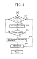
- FIG. 4 is a view showing a flowchart of the control according to Embodiment 1.
- FIG. 5 is a view showing a timing chart when engagement in the control according to Embodiment 1 was successful.
- FIG. 6 is a view showing a timing chart when engagement in the control according to Embodiment 1 failed.
- FIG. 7 is a view for illustrating control according to Embodiment 2.
- FIGS. 1 to 6 A first embodiment of the present invention will now be described with reference to FIGS. 1 to 6 .
- a vehicle 1 shown in FIG. 1 is a hybrid vehicle. As shown in FIG. 1 , the vehicle 1 is loaded with a motor 4 as an electric motor for transmitting a driving force to wheels 3 via a power transmission mechanism 2 . The vehicle 1 is also loaded with a high voltage battery 5 for supplying electric power to the motor 4 , and the high voltage battery 5 can be charged with electricity from the outside.
- a motor 4 as an electric motor for transmitting a driving force to wheels 3 via a power transmission mechanism 2 .
- the vehicle 1 is also loaded with a high voltage battery 5 for supplying electric power to the motor 4 , and the high voltage battery 5 can be charged with electricity from the outside.
- Engaging members 80 constituting the clutch 8 are composed of a first clutch plate (first engaging member) 81 located on the side of the engine 6 , and a second clutch plate (second engaging member) 82 located on the side of the motor 4 .
- a driving force from the engine 6 is transmitted to the wheels 3 via the clutch 8 and the power transmission mechanism 2 .
- the transmission path of this driving force is designated as a driving force transmission path.
- the above-mentioned vehicle 1 under normal conditions, is in a state where the clutch 8 is disengaged. In this state, no power is transmitted between the output system 7 and the power transmission mechanism 2 , and the vehicle 1 runs upon the driving of the motor 4 . That is, under the normal conditions, the vehicle 1 selects a travel mode which is a first travel mode (an EV travel mode and a series travel mode).
- a travel mode which is a first travel mode (an EV travel mode and a series travel mode).
- a path for transmitting a rotating force by the motor 4 in the first travel mode to the power transmission mechanism 2 is designated as a rotating force transmission path.
- the clutch 8 When a necessary driving output is not obtained any more by the driving force of the motor 4 in a high speed travel or the like, the clutch 8 is engaged, whereby the driving force of the engine 6 is transmitted to the power transmission mechanism 2 , with the result that the driving force of the engine 6 is added (or the driving force of the engine 6 alone is used) and, in this state, the vehicle 1 runs. That is, in this case, the vehicle 1 selects a travel mode which is a second travel mode (parallel travel mode).
- the vehicle 1 is equipped with a control unit 11 .
- the control unit 11 exercises the integrated control of the vehicle.
- the control unit 11 has a clutch control unit 12 as a clutch control device for switching the state of the clutch 8 as stated above.
- the clutch control unit 12 performs clutch control for engaging the clutch 8 when it is necessary to switch the vehicle to the parallel travel mode (second travel mode) while the vehicle is running in the series travel mode or the EV travel mode (first travel mode).
- the clutch control unit 12 is equipped with a clutch rotation control unit 21 , a clutch engagement control unit 22 , and a clutch mode control unit 23 .
- the vehicle 1 is also equipped with a vehicle speed detection unit 31 , a motor rotational number detection unit 32 , and an engine rotational number detection unit 33 which are used in the clutch control by the clutch control unit 12 .
- the respective detection units detect the vehicle speed, the motor rotational number, and the engine rotational number, respectively, based on the results of detection by relevant sensors. Each detection unit will be described in detail below.
- the clutch control unit 12 actuates the clutch rotation control unit 21 in the absence of a clutch engagement prohibition mode which will be described in detail later.
- the clutch rotation control unit 21 exercises control so as to match the rotational number of the first engaging member on the engine side to the rotational number of the second engaging member on the motor side, when the vehicle speed obtained from the vehicle speed detection unit 31 becomes a predetermined value or more (when the travel mode switches from the series travel mode (or the EV travel mode) to the parallel travel mode). Then, it is determined, based on the rotational numbers obtained from the motor rotational number detection unit 32 and the engine rotational number detection unit 33 , whether the rotation of the first engaging member and the rotation of the second engaging member have been synchronized to each other.
- Synchronization between the rotational numbers is performed by the generator driving the engine in such a manner that the rotational number of the first engaging member on the engine side equals (or nearly equals) the rotational number of the second engaging member on the motor side.
- the clutch rotation control unit 21 inputs a clutch engagement instruction signal to the clutch engagement control unit 22 .
- the clutch engagement control unit 22 drives a clutch solenoid valve to raise the clutch oil pressure, moving the engaging members in the axial direction.
- the clutch engagement control unit 22 determines whether or not engagement has been successfully carried out, based on whether the difference between the rotational numbers of the first engaging member and the second engaging member is within a predetermined value when a preset estimated time has elapsed since the start of movement of the engaging members. That is, if the rotational number difference after a lapse of the estimated time is within the predetermined value, it is determined that engagement has been successful. If the rotational number difference after a lapse of the estimated time is larger than the predetermined value, it is determined that the first engaging member and the second engaging member have failed to be engaged with each other.
- the estimated time is acquired by the clutch engagement control unit 22 from a map or table prestored in the clutch engagement control unit 22 .
- the map or table shows the relationship between the estimated time and a clutch-nonengageable determination count to be described later. In the map or table, the larger the clutch-nonengageable determination count, the longer the estimated time becomes.
- the clutch engagement control unit 22 determines that the engaging members have been successfully coupled (engaged), it retains the engagement of the clutch, so that the vehicle is switched to the parallel travel mode and continues to run.
- the clutch engagement control unit 22 determines that the engaging members 80 have failed to be coupled (engaged)
- the clutch engagement control unit 22 terminates the engagement control of the clutch, releasing the engaging members. That is, the vehicle cannot be switched to the parallel travel mode, and runs in the series travel mode (or the EV travel mode).
- the clutch mode control unit 23 decides that the clutch engagement control unit 22 has failed in engaging the engaging members 80 , the clutch mode control unit 23 sets a determination flag, and counts up the clutch-nonengageable determination count. That is, the clutch-nonengageable determination count is increased from N to N+1.
- the clutch mode control unit 23 continues to feed out the clutch engagement prohibition mode to the clutch control unit 12 until the vehicle stops. This is because a sufficient time is provided by the time the viscosity of the clutch oil recovers, since continuous retries during travel of the vehicle have the possibility that engagement will fail again.
- the clutch control unit 12 does not perform clutch engagement, as already mentioned, even if in an operating state ensuring the parallel travel mode.
- the clutch mode control unit 23 clears the flag to execute a clutch engagement authorization mode.
- the clutch control unit 12 can carry out clutch engagement again in order to switch the vehicle to the parallel travel mode while the vehicle is running in the series travel mode or the EV travel mode.
- the estimated time to be set by the clutch engagement control unit 22 is set by the map which the clutch engagement control unit 22 prestores, as stated above.
- the clutch-nonengageable determination count (N+1) in the present control is larger by 1 than the clutch-nonengageable determination count (N) in the previous control.
- the estimated time in the present control is longer than the estimated time in the previous control. Since the activating time for the clutch becomes longer than that at the time of the previous clutch engagement determination, the oil temperature of the clutch rises. As a result of this temperature rise, when the engaging members can engage, the rotational numbers of the engaging members become equal. Based on this fact, the clutch engagement control unit 22 decides that the clutch has been engaged. Thus, the vehicle is switched to the parallel travel mode.
- the clutch engagement control unit 22 determines that the reengagement of the engaging members has failed. Based on this determination, the same process as described above is performed. As the clutch-nonengageable determination count is increased, the estimated time is lengthened by the clutch engagement control unit 22 .
- whether the engaging members of the clutch have been engaged or not is determined by the difference between the rotational numbers of the respective engaging members when a predetermined estimated time has elapsed (namely, when a predetermined connection time has elapsed) since the start of determination (i.e., since the start of movement of the engaging members).
- the clutch control unit 12 determines that the clutch is failing.
- the clutch control unit exercises control as shown in the flowcharts when the aforementioned clutch engagement authorization mode is executed.
- step S 1 the clutch control unit decides whether or not the vehicle speed required by the driver is higher than a parallel determination vehicle speed at which the series travel mode (or the EV travel mode) should be switched to the parallel travel mode. If the vehicle speed required by the driver is equal to or higher than the parallel determination vehicle speed (YES), the program proceeds to step S 2 . If the vehicle speed required by the driver is lower than the parallel determination vehicle speed (NO), the vehicle maintains the series travel mode (or the EV travel mode) as such.
- step S 2 synchronization of the rotations of the engaging members of the clutch is started for a shift to the parallel travel mode.
- the rotation of the first engaging member (the engaging member on the engine side) is increased by the generator so as to be synchronized to the rotation of the second engaging member (the engaging member on the motor side).
- step S 3 it is determined whether or not the rotations of, the first engaging member and the second engaging member are synchronized to each other. If their rotational numbers are each within a predetermined range (YES), the program proceeds to step S 4 . If the rotational numbers are still outside the predetermined range (NO), the program returns to step S 2 .
- step S 4 a clutch engagement instruction signal is inputted, whereupon the clutch engagement control unit starts control. That is, the clutch engagement control unit exerts a hydraulic pressure on the engaging members 80 to increase the pressure on the engaging members, thereby starting engagement.
- the program proceeds to step S 5 .
- step S 5 the clutch engagement control unit 22 performs clutch engagement determination control. That is, the measurement of the estimated time is started.
- the program proceeds to step S 6 .
- Step S 4 and step S 5 may be executed simultaneously.
- step S 6 the clutch engagement control unit 22 performs determination of the engagement of the engaging members. That is, whether or not the engaging members have been successfully engaged is determined according to whether or not the rotational numbers of the first engaging member and the second engaging member at a preset estimated time after start of engagement are within a predetermined value. If the rotational numbers after a lapse of the estimated time are within the predetermined value (YES), it is determined that engagement has been successful, and the vehicle maintains its state unchanged. The program proceeds to step S 10 .
- step S 6 if the rotational numbers after a lapse of the estimated time are greater than the predetermined value (NO), the clutch engagement control unit 22 determines that the engaging members have not been engaged successfully. This is because the engaging members have been nonengageable, and the engagement of the clutch has not been accomplished, so that the clutch is in a partially engaged state, thereby producing a rotational number difference.
- the program proceeds to step S 7 .
- step S 7 the clutch engagement control unit terminates the engagement control of the clutch to release the engaging members.
- the program proceeds to step S 8 .
- the program proceeds to step S 9 .
- step S 9 the clutch mode control unit counts up the clutch-nonengageable determination count (it is increased from N to N+1). Under these conditions, the vehicle is not switched to the parallel travel mode, but runs in the series travel mode (or the EV travel mode). The program proceeds to step S 11 .
- step S 10 the counted-up clutch-nonengageable determination count is reset.
- the travel mode is shifted to the parallel travel mode.
- steps S 1 to S 10 deal with the control for shift from the series travel mode to the parallel travel mode.
- Steps S 11 to S 15 to be described below are concerned with control over the determination of the clutch engagement mode during travel.
- step S 12 the clutch mode control unit sets the clutch engagement prohibition mode.
- the program proceeds to step 513 .
- step S 13 the clutch mode control unit determines whether the vehicle is stationary or not. If the vehicle is stationary (YES), the program proceeds to step S 14 . When the vehicle is not stationary (NO), the program returns to step S 11 . That is, the clutch engagement prohibition mode continues until the vehicle stops.
- step S 14 when the vehicle stops, the clutch-nonengageable determination flag is released.
- the program proceeds to step S 15 .
- step S 15 the clutch mode control unit sets the clutch engagement authorization mode.
- the vehicle enters the clutch engagement authorization mode.
- the travel mode should be switched from the series travel mode (or the EV travel mode) to the parallel travel mode, thereby the clutch can be engaged.
- the clutch mode control unit sets the clutch engagement prohibition mode
- the clutch control unit does not engage the clutch until the vehicle becomes stationary.
- the clutch mode control unit sets the clutch engagement authorization mode again after the vehicle stops, the clutch control unit performs engagement of the clutch.
- the estimated time in the determination of engagement of the clutch is rendered longer than that of the previous estimation, whereby the clutch is made easier to engage.
- the clutch control unit exercises the engagement control of the clutch in accordance with the above-mentioned flowcharts.
- whether the engaging members of the clutch have been engaged or not is determined by the difference between the rotational numbers of the respective engaging members when a predetermined estimated time has elapsed (namely, when a predetermined connection time has elapsed) since the start of determination (i.e., since the start of movement of the engaging members).
- the rotational number of the engine is increased by the clutch rotational number control unit to be synchronized to the rotational number of the motor.
- clutch engagement control by the clutch engagement control unit is started and, at the same time, the estimated time begins to be measured.
- clutch engagement control is begun, the clutch pressure begins to rise, and the first engaging member and the second engaging member move in the axial direction.
- the vehicle switches the source of driving force from the motor to the engine, so that reversal between the torque of the motor and the torque of the engine is begun.
- the clutch engagement control unit compares the rotational number of the motor and the rotational number of the engine that have been detected. Since their values are within the predetermined value, the clutch engagement control unit determines that the engaging members have been engaged. Thus, the vehicle is shifted substantially to the parallel travel mode.
- clutch engagement control by the clutch engagement control unit is started and, at the same time, the estimated time begins to be measured.
- clutch engagement control is begun, the clutch pressure begins to rise, and the respective engaging members move in the axial direction, whereby clutch is engaged.
- the clutch engagement control unit compares the rotational number of the motor and the rotational number of the engine that have been detected. Since their values are equal to or more than the predetermined value, the clutch engagement control unit determines that the engaging members have not been engaged completely. Thus, the clutch engagement instruction signal is turned off, and the clutch pressure is released.
- FIG. 7 A second embodiment of the present invention will be described using FIG. 7 .
- the clutch engagement control unit also considers the clutch oil temperature in setting the estimated time. This is a difference from the first embodiment.
- the clutch engagement control unit compares an estimated time based on the oil temperature of the clutch (a second set time) with an estimated time based on the clutch-nonengageable determination count (a first set time), and sets the second set time or the first set time, whichever is longer, as the estimated time.
- the estimated time based on the oil temperature of the clutch and the estimated time based on the clutch-nonengageable determination count may be multiplied by their coefficients to set the estimated time.
- the clutch engagement control unit detects the oil temperature of the clutch, and acquires it. As shown in FIG. 7 , the estimated time versus the oil temperature of the clutch is such that the higher the oil temperature of the clutch, the shorter the estimated time becomes. That is, as the oil temperature of the clutch rises, the viscosity of the oil lowers, and the engaging members become easier to engage. Thus, the estimated time to be taken for determination of whether engagement has been successful or unsuccessful can be shortened.
- the clutch-nonengageable determination count and the estimated time are in such a relation that as the clutch-nonengageable determination count increases, the estimated time lengthens, as shown in FIG. 7 . That is, the higher the clutch-nonengageable determination count, the more difficultly the clutch has engaging. Thus, the estimated time is rendered longer to make clutch engagement easier.
- the clutch engagement control unit acquires the estimated time with respect to the oil temperature of the clutch and the estimated time with respect to the clutch-nonengageable determination count, compares both estimated times, and sets the longer of the estimated times as the estimated time.
- the estimated time based on the oil temperature is initially longer than the estimated time based on the clutch-nonengageable determination count, the estimated time based on the oil temperature is set as the estimated time. Then, the estimated time based on the clutch-nonengageable determination count is longer than the estimated time based on the oil temperature, and is thus set as the estimated time.
- both estimated times are compared, and the longer estimated time is preferentially set as the estimated time. Because of this feature, in the present embodiment, determination by the clutch engagement control unit can be made more reliably and more accurately, and the clutch can be engaged more easily with a single determination. That is, the predetermined time can be set more appropriately depending on the state of the clutch.
- the embodiments of the present invention are not limited to the ones described above.
- switching from the series travel mode to the parallel travel mode has been explained, but this is not limitative.
- switching from the EV travel mode to the parallel travel mode the same embodiments hold true.
- the vehicle runs, with only the engine as the drive source, in the parallel travel mode, but this is not limitative.
- the vehicle may run, with both the engine and the motor serving as the drive source.
- the clutch control device of a hybrid vehicle according to the present invention can be used in a hybrid vehicle. Hence, it is applicable in the automobile manufacturing industry.
Landscapes
- Engineering & Computer Science (AREA)
- Mechanical Engineering (AREA)
- Transportation (AREA)
- Chemical & Material Sciences (AREA)
- Combustion & Propulsion (AREA)
- General Engineering & Computer Science (AREA)
- Physics & Mathematics (AREA)
- Fluid Mechanics (AREA)
- Automation & Control Theory (AREA)
- Hybrid Electric Vehicles (AREA)
- Hydraulic Clutches, Magnetic Clutches, Fluid Clutches, And Fluid Joints (AREA)
Abstract
Description
- [Patent Document 1] JP-A-2010-281397
- 1 Vehicle
- 2 Power transmission mechanism
- 3 Wheel
- 4 Motor
- 5 High voltage battery
- 6 Engine
- 7 Output system
- 8 Clutch
- 9 Generator
- 10 Inverter
- 11 Control unit
- 12 Clutch control unit (determination means)
- 21 Clutch rotation control unit
- 22 Clutch engagement control unit
- 23 Clutch mode control unit
- 31 Vehicle speed detection unit
- 32 Motor rotational number detection unit
- 33 Engine rotational number detection unit
- 80 Engaging members
- 81 First Engaging member (first clutch plate)
- 82 Second engaging member (second clutch plate)
Claims (5)
Applications Claiming Priority (2)
| Application Number | Priority Date | Filing Date | Title |
|---|---|---|---|
| JP2011272804A JP5892315B2 (en) | 2011-12-13 | 2011-12-13 | Clutch control device for hybrid vehicle |
| JP2011-272804 | 2011-12-13 |
Publications (2)
| Publication Number | Publication Date |
|---|---|
| US20130150206A1 US20130150206A1 (en) | 2013-06-13 |
| US8608616B2 true US8608616B2 (en) | 2013-12-17 |
Family
ID=47602882
Family Applications (1)
| Application Number | Title | Priority Date | Filing Date |
|---|---|---|---|
| US13/712,559 Expired - Fee Related US8608616B2 (en) | 2011-12-13 | 2012-12-12 | Clutch control device of hybrid vehicle |
Country Status (4)
| Country | Link |
|---|---|
| US (1) | US8608616B2 (en) |
| EP (1) | EP2604880B1 (en) |
| JP (1) | JP5892315B2 (en) |
| CN (1) | CN103158694B (en) |
Cited By (1)
| Publication number | Priority date | Publication date | Assignee | Title |
|---|---|---|---|---|
| US20150232080A1 (en) * | 2014-02-17 | 2015-08-20 | Hyundai Motor Company | Mode control apparatus of hybrid vehicle and control method thereof |
Families Citing this family (7)
| Publication number | Priority date | Publication date | Assignee | Title |
|---|---|---|---|---|
| JP6079521B2 (en) * | 2013-09-13 | 2017-02-15 | 日産自動車株式会社 | Hybrid vehicle |
| KR101509943B1 (en) * | 2013-10-22 | 2015-04-07 | 현대자동차주식회사 | Fail-Safe Control Method for a clutch actuator of the Engine and the apparatus thereof |
| JP6304173B2 (en) * | 2015-08-18 | 2018-04-04 | トヨタ自動車株式会社 | vehicle |
| KR102278348B1 (en) * | 2017-06-29 | 2021-07-19 | 현대자동차주식회사 | Vehicle and method for controlling the same |
| JP7163837B2 (en) * | 2019-03-20 | 2022-11-01 | トヨタ自動車株式会社 | Hybrid vehicle control device |
| CN110410491B (en) * | 2019-07-29 | 2020-08-18 | 北京航空航天大学 | A kind of automatic transmission shifting control method and device |
| CN118257796A (en) * | 2022-12-27 | 2024-06-28 | 广州汽车集团股份有限公司 | Clutch oil pressure control method and device of automobile electromechanical coupling system and electronic equipment |
Citations (7)
| Publication number | Priority date | Publication date | Assignee | Title |
|---|---|---|---|---|
| US6810669B2 (en) * | 2001-06-28 | 2004-11-02 | Mitsubishi Heavy Industries, Ltd. | Clutch engagement detector and uniaxial combined plant having the detector |
| EP1762452A2 (en) | 2005-09-08 | 2007-03-14 | Nissan Motor Co., Ltd. | Engine starting control device and method |
| US20080096717A1 (en) * | 2003-05-30 | 2008-04-24 | Lg Electronics Inc. | Hybrid Drive Train For Vehicle |
| JP2010281397A (en) | 2009-06-04 | 2010-12-16 | Toyota Motor Corp | Clutch control device |
| WO2011079740A1 (en) | 2009-12-31 | 2011-07-07 | Byd Company Limited | Hybrid power driving system and driving method of the same |
| US20110295476A1 (en) | 2010-05-28 | 2011-12-01 | Honda Motor Co., Ltd. | System For And Method Of Detecting Clutch Engagement Of A Manual Transmission |
| US20120089285A1 (en) * | 2010-10-08 | 2012-04-12 | Yukihiro Nissato | Clutch control device of hybrid vehicle |
Family Cites Families (13)
| Publication number | Priority date | Publication date | Assignee | Title |
|---|---|---|---|---|
| JP3303699B2 (en) * | 1996-12-25 | 2002-07-22 | 日産自動車株式会社 | Fail safe device for creep prevention device for automatic transmission |
| JP3870505B2 (en) * | 1997-08-29 | 2007-01-17 | アイシン・エィ・ダブリュ株式会社 | Hybrid drive device for vehicle |
| JP2002144921A (en) * | 2000-11-15 | 2002-05-22 | Mitsubishi Motors Corp | Hybrid vehicle control device |
| CN1301200C (en) * | 2002-09-13 | 2007-02-21 | 本田技研工业株式会社 | hybrid vehicle |
| DE10260435A1 (en) * | 2002-12-21 | 2004-07-01 | Volkswagen Ag | Controlling motor vehicle hybrid drive involves accelerating with electrical machine, starting engine, accelerating with electrical machine and engine with suitable operation of two clutches |
| DE10353256B3 (en) * | 2003-11-14 | 2005-03-31 | Barske, Heiko, Dr. | Automobile hybrid drive system with common control of converter unit between electrical machine driven by IC engine and electrical energy store and clutches on input and output sides of electrical machine |
| JP4396468B2 (en) * | 2004-09-29 | 2010-01-13 | 井関農機株式会社 | Shift control device for moving vehicle |
| JP4626985B2 (en) * | 2005-02-22 | 2011-02-09 | 日立オートモティブシステムズ株式会社 | Fastening pressure control device for friction engagement element |
| JP2007069817A (en) * | 2005-09-08 | 2007-03-22 | Nissan Motor Co Ltd | Engine start control device for hybrid vehicle |
| JP2007069804A (en) * | 2005-09-08 | 2007-03-22 | Nissan Motor Co Ltd | Engine start response improving device for hybrid vehicle |
| JP2007320388A (en) * | 2006-05-31 | 2007-12-13 | Honda Motor Co Ltd | Control device for hybrid vehicle |
| JP2009092119A (en) * | 2007-10-05 | 2009-04-30 | Toyota Motor Corp | Vehicle hydraulic control device |
| JP5453826B2 (en) * | 2009-02-06 | 2014-03-26 | 日産自動車株式会社 | Vehicle control device |
-
2011
- 2011-12-13 JP JP2011272804A patent/JP5892315B2/en not_active Expired - Fee Related
-
2012
- 2012-12-12 US US13/712,559 patent/US8608616B2/en not_active Expired - Fee Related
- 2012-12-12 CN CN201210536849.1A patent/CN103158694B/en not_active Expired - Fee Related
- 2012-12-12 EP EP12196659.2A patent/EP2604880B1/en not_active Not-in-force
Patent Citations (8)
| Publication number | Priority date | Publication date | Assignee | Title |
|---|---|---|---|---|
| US6810669B2 (en) * | 2001-06-28 | 2004-11-02 | Mitsubishi Heavy Industries, Ltd. | Clutch engagement detector and uniaxial combined plant having the detector |
| US20080096717A1 (en) * | 2003-05-30 | 2008-04-24 | Lg Electronics Inc. | Hybrid Drive Train For Vehicle |
| EP1762452A2 (en) | 2005-09-08 | 2007-03-14 | Nissan Motor Co., Ltd. | Engine starting control device and method |
| JP2010281397A (en) | 2009-06-04 | 2010-12-16 | Toyota Motor Corp | Clutch control device |
| WO2011079740A1 (en) | 2009-12-31 | 2011-07-07 | Byd Company Limited | Hybrid power driving system and driving method of the same |
| US20110295476A1 (en) | 2010-05-28 | 2011-12-01 | Honda Motor Co., Ltd. | System For And Method Of Detecting Clutch Engagement Of A Manual Transmission |
| US8412428B2 (en) * | 2010-05-28 | 2013-04-02 | Honda Motor Co., Ltd. | System for and method of detecting clutch engagement of a manual transmission |
| US20120089285A1 (en) * | 2010-10-08 | 2012-04-12 | Yukihiro Nissato | Clutch control device of hybrid vehicle |
Cited By (2)
| Publication number | Priority date | Publication date | Assignee | Title |
|---|---|---|---|---|
| US20150232080A1 (en) * | 2014-02-17 | 2015-08-20 | Hyundai Motor Company | Mode control apparatus of hybrid vehicle and control method thereof |
| US9862369B2 (en) * | 2014-02-17 | 2018-01-09 | Hyundai Motor Company | Mode control apparatus of hybrid vehicle and control method thereof |
Also Published As
| Publication number | Publication date |
|---|---|
| EP2604880B1 (en) | 2017-06-07 |
| US20130150206A1 (en) | 2013-06-13 |
| CN103158694A (en) | 2013-06-19 |
| EP2604880A1 (en) | 2013-06-19 |
| JP5892315B2 (en) | 2016-03-23 |
| CN103158694B (en) | 2016-01-20 |
| JP2013123964A (en) | 2013-06-24 |
Similar Documents
| Publication | Publication Date | Title |
|---|---|---|
| US8608616B2 (en) | Clutch control device of hybrid vehicle | |
| KR101283044B1 (en) | Control method for vehicle drive source of hybrid vehicle in breakdown of transmission gear step | |
| KR100941239B1 (en) | Torque control method of hybrid vehicle | |
| KR101047399B1 (en) | How to Correct Clutch Characteristics in Hybrid Vehicles | |
| CN104507775B (en) | Control device of electric motor | |
| KR102518585B1 (en) | Method and device for controlling engine clutch of hybrid vehicle | |
| KR101459437B1 (en) | Method and system for controlling connection of engine clutch of hybrid electric vehicle | |
| KR101360060B1 (en) | Method and system for controlling engine start when starter motor of hybrid electric vehicle is failure | |
| KR101484215B1 (en) | Method and system for starting engine when starter motor of hybrid electric vehicle is in trouble | |
| US9616884B1 (en) | Apparatus and method for controlling hybrid electric vehicle including dual clutch transmission | |
| US20160244050A1 (en) | Startup control device and startup control method for hybrid vehicle | |
| US20080190675A1 (en) | Vehicle Driving System | |
| KR101684525B1 (en) | Apparatus and method for learning touch point of engine clutch of hybrid electric vehicle | |
| KR101550631B1 (en) | Method and system for activating catalyst of hybrid vehicle | |
| CN102442305A (en) | Clutch control device of hybrid vehicle | |
| EP3053793B1 (en) | Device and method for controlling hybrid vehicle | |
| US12000441B2 (en) | Vehicle clutch control method and vehicle clutch control device | |
| CN105813913A (en) | Method for increasing the availability of a hybrid disconnect clutch in a hybrid drive train of a motor vehicle | |
| KR101776524B1 (en) | Method for monitoring connecting status of engine clutch | |
| US10480478B2 (en) | Diagnostic techniques for a clutch interlock switch and a clutch pedal position sensor | |
| CN107933547B (en) | Method and system for controlling travel mode of hybrid vehicle | |
| KR102064693B1 (en) | Abnormality detection device of automatic transmission | |
| KR101519797B1 (en) | Robust control method for engine clutch of hybrid electric vehicle | |
| JP5391702B2 (en) | Control device for hybrid vehicle | |
| KR101610585B1 (en) | Kiss point learning method for engine clutch of hybrid electric vehicle |
Legal Events
| Date | Code | Title | Description |
|---|---|---|---|
| AS | Assignment |
Owner name: MITSUBISHI JIDOSHA KOGYO KABUSHIKI KAISHA, JAPAN Free format text: ASSIGNMENT OF ASSIGNORS INTEREST;ASSIGNOR:NISSATO, YUKIHIRO;REEL/FRAME:029466/0275 Effective date: 20121127 |
|
| FEPP | Fee payment procedure |
Free format text: PAYOR NUMBER ASSIGNED (ORIGINAL EVENT CODE: ASPN); ENTITY STATUS OF PATENT OWNER: LARGE ENTITY |
|
| STCF | Information on status: patent grant |
Free format text: PATENTED CASE |
|
| FPAY | Fee payment |
Year of fee payment: 4 |
|
| AS | Assignment |
Owner name: MITSUBISHI JIDOSHA KOGYO KABUSHIKI KAISHA, JAPAN Free format text: CHANGE OF ADDRESS;ASSIGNOR:MITSUBISHI JIDOSHA KOGYO KABUSHIKI KAISHA;REEL/FRAME:055472/0944 Effective date: 20190104 |
|
| MAFP | Maintenance fee payment |
Free format text: PAYMENT OF MAINTENANCE FEE, 8TH YEAR, LARGE ENTITY (ORIGINAL EVENT CODE: M1552); ENTITY STATUS OF PATENT OWNER: LARGE ENTITY Year of fee payment: 8 |
|
| FEPP | Fee payment procedure |
Free format text: MAINTENANCE FEE REMINDER MAILED (ORIGINAL EVENT CODE: REM.); ENTITY STATUS OF PATENT OWNER: LARGE ENTITY |
|
| LAPS | Lapse for failure to pay maintenance fees |
Free format text: PATENT EXPIRED FOR FAILURE TO PAY MAINTENANCE FEES (ORIGINAL EVENT CODE: EXP.); ENTITY STATUS OF PATENT OWNER: LARGE ENTITY |
|
| STCH | Information on status: patent discontinuation |
Free format text: PATENT EXPIRED DUE TO NONPAYMENT OF MAINTENANCE FEES UNDER 37 CFR 1.362 |
|
| FP | Lapsed due to failure to pay maintenance fee |
Effective date: 20251217 |