US8607955B2 - Release for pull type clutch mechanism - Google Patents
Release for pull type clutch mechanism Download PDFInfo
- Publication number
- US8607955B2 US8607955B2 US13/310,908 US201113310908A US8607955B2 US 8607955 B2 US8607955 B2 US 8607955B2 US 201113310908 A US201113310908 A US 201113310908A US 8607955 B2 US8607955 B2 US 8607955B2
- Authority
- US
- United States
- Prior art keywords
- segments
- gaps
- cut
- ring
- basket
- Prior art date
- Legal status (The legal status is an assumption and is not a legal conclusion. Google has not performed a legal analysis and makes no representation as to the accuracy of the status listed.)
- Expired - Fee Related, expires
Links
Images


Classifications
-
- F—MECHANICAL ENGINEERING; LIGHTING; HEATING; WEAPONS; BLASTING
- F16—ENGINEERING ELEMENTS AND UNITS; GENERAL MEASURES FOR PRODUCING AND MAINTAINING EFFECTIVE FUNCTIONING OF MACHINES OR INSTALLATIONS; THERMAL INSULATION IN GENERAL
- F16D—COUPLINGS FOR TRANSMITTING ROTATION; CLUTCHES; BRAKES
- F16D23/00—Details of mechanically-actuated clutches not specific for one distinct type
- F16D23/12—Mechanical clutch-actuating mechanisms arranged outside the clutch as such
- F16D23/14—Clutch-actuating sleeves or bearings; Actuating members directly connected to clutch-actuating sleeves or bearings
- F16D23/143—Arrangements or details for the connection between the release bearing and the diaphragm
- F16D23/144—With a disengaging thrust-ring distinct from the release bearing, and secured to the diaphragm
- F16D23/146—Arrangements for the connection between the thrust-ring and the release bearing
Definitions
- the invention relates to a release mechanism for a friction clutch used in automobiles.
- Pull type clutches are well known in the art. They generally include a release mechanism that pulls a radially inner portion of a diaphragm spring toward a transmission to disengage the clutch.
- One such apparatus includes a pressure plate and one pushes on the clutch pedal to make it operate.
- the pressure plate is mounted to the engine and a release bearing is mounted to the pressure plate on the transmission side.
- the release bearing can be disengaged by pushing it and releasing the snap ring and inserting a screwdriver between the bearing and the pressure plate, thus releasing the same from the wedge collar. This releases the pressure plate from the transmission.
- the snap ring retaining the wedge collar to the pressure plate expands in high RPM use applications. If one shifts very fast, under adverse conditions such as often experienced in racing, the bearing can jump out of place causing the snap ring to jump out of place and be exposed, damaging parts and resulting in breakdown of the clutch mechanism requiring removal of the transmission.
- FIG. 1 is an exploded view of a pull type clutch mechanism in accordance with the teachings of the invention
- FIG. 2 is a top plan view of the retaining basket alone of the clutch mechanism of FIG. 1 ;
- FIG. 3 is a side view of the basket of FIG. 2 ;
- FIG. 4 is a view taken along lines 4 - 4 of FIG. 2 ;
- FIG. 5 is an exploded view illustrating the assembly of the throw out bearing of FIG. 1 to the retaining basket mounted to the pressure plate of FIG. 1 ;
- FIG. 6 is a plan view illustrating the assembly of the parts of FIG. 5 ;
- FIG. 7 is a cross-sectional view of the assembled parts in FIG. 6 mounted to the transmission and engine of a vehicle;
- FIG. 8 is a perspective view of a modified retaining basket in accordance with the teachings of the invention.
- FIG. 9 is a side view of the bracket of FIG. 8 ;
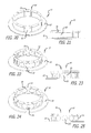
- FIGS. 10 , 12 , 14 , 16 , 18 , 20 , 22 and 24 are perspective views of further modifications of the basket of FIG. 1 ;
- FIGS. 11 , 13 , 15 , 17 , 19 , 21 , 23 and 25 are side views of the respective baskets of FIGS. 10 , 12 , 14 , 16 , 18 , 20 , 22 and 24 .
- Clutch assembly 10 is shown in exploded view in FIG. 1 .
- Assembly 10 includes a throw-out bearing 11 , a retaining basket 12 , a pressure plate 13 , a clutch disk 14 and a flywheel 15 .
- Clutch assembly 10 is adapted to be secured to flywheel 15 using suitable bolts 16 extending through aligned holes 17 , 18 in pressure plate 13 and flywheel 15 and then to the motor (not shown).
- a spline shaft extends from the vehicle transmission (not shown) through aligned holes 19 to 22 in bearing 11 , basket 12 , pressure plate 13 and flywheel 15 into engagement with spline 23 in hole 22 of the clutch disk 14 .
- the retaining basket 12 as seen in FIG. 2 , has a generally flat annular ring portion 24 with an integral split ring 25 , of lesser diameter than ring portion 24 .
- ring portion 24 is formed of arcuate segments 26 , one spaced from another by gaps 28 . These segments 26 are integral with ring portion 24 by means of solid connecting portions 27 .
- portions 27 are generally open and oval spaced from adjacent portions 27 and open at top communicating with gaps 28 . This arrangement, as will be discussed, results in the maximum amount of ring 25 across the top or upper end of basket 12 , as seen in FIGS. 3 and 4 , with respect to the flexibility required to allow the basket 12 to snap into position as will be discussed.
- throw-out bearing 11 is now press-fit down into the hole 20 through basket 12 .
- the final installed position is shown in FIG. 6 .
- bearing 11 has a downwardly extending cylindrical portion 36 with an outer annular groove 32 into which ring 26 snap-fits.
- Bearing 11 terminates at top in a bracket 33 and the upper body portion 34 rotates with respect to cylindrical portion 36 by means of a ball bearing assembly 35 as is well known in the art.
- Pressure plate 13 has an annular groove 31 into which ring 26 snap-fits as seen in FIG. 7 .
- the throw-out bearing 11 is attached to the basket 12 and thus to the pressure plate 13 .
- the bracket 33 of the throw-out bearing 11 is tied to the yoke of the transmission (not shown), as is well known in the art, and thus this pushes the bearing 11 in and out to activate the clutch (not shown).
- annular spring washers may be disposed between the throw-out bearing 11 and collar 30 , to take up any slop between the parts.
- FIG. 1 It can be seen that the parts illustrated in FIG. 1 can be quickly and easily assembled. When the retaining bracket 11 is released from the pressure plate 13 , the entire assembly can be disengaged from the transmission.
- a first modified basket 40 is shown having a flat annular ring portion 41 with a plurality of spaced segments 42 integral with ring portion 41 and terminating in a ring 43 (similar to ring 26 ) comprising of arcuate portions 45 separating by gaps 44 .
- the segments 42 are generally rectangular.
- basket 46 has a flat annular ring portion 47 and a plurality of spaced segments 48 integral with ring portion 47 terminating in a ring 49 .
- Ring 49 is formed of spaced portions 50 , which may be slightly arcuate, separated by gaps 51 . It is noted that segments 48 are elongated rectangles and the gaps 51 are wider than gaps 44 in FIG. 8 .
- basket 52 also has a flat annular ring portion 53 and a plurality of spaced segments 54 terminating in a ring 55 . It is noted that the gaps 56 between the arcuate segments 57 forming ring 55 communicate with an oval-shaped opening 58 between adjacent segments 54 .
- basket 59 has a flat annular ring portion 60 with a plurality of spaced segments 61 . Segments 61 terminate in a ring 62 comprising of spaced arcuate segments 63 separated by gaps 64 , 65 . Gaps 64 are elongated slots and gaps 65 communicate with rounded openings 66 between adjacent segments 61 . A pair of such segments 61 having openings 66 therebetween are separated by elongated gaps 64 .
- FIGS. 16 and 17 Another variation of the retaining basket is shown in FIGS. 16 and 17 .
- basket 67 has a flat annular ring portion 68 with integral spaced segments 69 .
- a gap 70 separates the arcuate ring segments 71 forming ring 72 .
- circular openings 73 communicating with gaps 70 are provided between adjacent segments 69 .
- basket 74 has a flat annular ring portion 75 with integral spaced segments 76 terminating in a ring 77 .
- Ring 77 is formed of curved portions 78 separated by gaps 79 .
- Gaps 79 communicate with generally circular openings 80 between adjacent segments 76 .
- basket 81 has a flat annular ring portion 82 with a plurality of integral spaced segments 83 . Segments 83 are generally rectangular terminating in a ring 84 . Ring 84 is formed of a plurality of spaced arcuate segments 85 separated by gaps 86 . As seen, gaps 86 are elongated slots.
- basket 87 has a flat annular ring portion 88 and a plurality of integral spaced segments 89 . Segments 89 terminate in a ring 90 comprised of a plurality of spaced arcuate segments 91 separated by gaps 92 . Gaps 92 communicate with generally oval-shaped cut-out openings 93 between adjacent segments 89 .
- FIGS. 24 and 25 A final embodiment of the basket is shown in FIGS. 24 and 25 .
- basket 94 has a flat annular ring portion 95 with a plurality of spaced segments 96 terminating in a ring 97 .
- Ring 97 is comprised of a plurality of arcuate segments 98 which may be crimped as shown separated by gaps 99 .
- Gaps 99 communicate with generally circular cut-out openings 100 between adjacent segments 96 .
- FIGS. 8 to 25 The operation of all of the baskets in FIGS. 8 to 25 is identical to the operation of basket 12 of FIG. 1 and further discussion or elaboration is deemed unnecessary. It can be seen that there is disclosed an improved wedge collar assembly for a pull-type clutch assembly having the snap ring integral with the wedge collar.
- the segmented ring of the snap ring of the invention expands uniformly and cannot jump out of place.
Landscapes
- Engineering & Computer Science (AREA)
- General Engineering & Computer Science (AREA)
- Mechanical Engineering (AREA)
- Mechanical Operated Clutches (AREA)
Abstract
Description
Claims (15)
Priority Applications (1)
| Application Number | Priority Date | Filing Date | Title |
|---|---|---|---|
| US13/310,908 US8607955B2 (en) | 2011-12-05 | 2011-12-05 | Release for pull type clutch mechanism |
Applications Claiming Priority (1)
| Application Number | Priority Date | Filing Date | Title |
|---|---|---|---|
| US13/310,908 US8607955B2 (en) | 2011-12-05 | 2011-12-05 | Release for pull type clutch mechanism |
Publications (2)
| Publication Number | Publication Date |
|---|---|
| US20130140129A1 US20130140129A1 (en) | 2013-06-06 |
| US8607955B2 true US8607955B2 (en) | 2013-12-17 |
Family
ID=48523215
Family Applications (1)
| Application Number | Title | Priority Date | Filing Date |
|---|---|---|---|
| US13/310,908 Expired - Fee Related US8607955B2 (en) | 2011-12-05 | 2011-12-05 | Release for pull type clutch mechanism |
Country Status (1)
| Country | Link |
|---|---|
| US (1) | US8607955B2 (en) |
Citations (6)
| Publication number | Priority date | Publication date | Assignee | Title |
|---|---|---|---|---|
| US4588061A (en) * | 1983-04-26 | 1986-05-13 | Valeo | Clutch release bearing assembly, coupling member for same and installation and removal methods for same |
| US4632237A (en) * | 1982-11-19 | 1986-12-30 | Automotive Products Plc | Friction clutch for a vehicle |
| US4903807A (en) | 1986-04-18 | 1990-02-27 | Kabushiki Kaisha Daikin Seisakusho | Release bearing mechanism of a clutch |
| US5240097A (en) * | 1990-05-10 | 1993-08-31 | Kabushiki Kaisha Daikin Seisakosho | Pull-type clutch |
| US5758757A (en) | 1996-07-17 | 1998-06-02 | Exedy Corporation | Wire ring retaining collar and release device for a pull type clutch mechanism |
| US20050236250A1 (en) * | 2004-04-24 | 2005-10-27 | Zf Friedrichshafen Ag | Release device for a friction clutch |
-
2011
- 2011-12-05 US US13/310,908 patent/US8607955B2/en not_active Expired - Fee Related
Patent Citations (6)
| Publication number | Priority date | Publication date | Assignee | Title |
|---|---|---|---|---|
| US4632237A (en) * | 1982-11-19 | 1986-12-30 | Automotive Products Plc | Friction clutch for a vehicle |
| US4588061A (en) * | 1983-04-26 | 1986-05-13 | Valeo | Clutch release bearing assembly, coupling member for same and installation and removal methods for same |
| US4903807A (en) | 1986-04-18 | 1990-02-27 | Kabushiki Kaisha Daikin Seisakusho | Release bearing mechanism of a clutch |
| US5240097A (en) * | 1990-05-10 | 1993-08-31 | Kabushiki Kaisha Daikin Seisakosho | Pull-type clutch |
| US5758757A (en) | 1996-07-17 | 1998-06-02 | Exedy Corporation | Wire ring retaining collar and release device for a pull type clutch mechanism |
| US20050236250A1 (en) * | 2004-04-24 | 2005-10-27 | Zf Friedrichshafen Ag | Release device for a friction clutch |
Also Published As
| Publication number | Publication date |
|---|---|
| US20130140129A1 (en) | 2013-06-06 |
Similar Documents
| Publication | Publication Date | Title |
|---|---|---|
| CN108457998B (en) | Method and apparatus for reducing clutch and brake drag using springs | |
| US10145458B2 (en) | Torque converter drive assembly including bias spring and axially movable turbine | |
| US20150008090A1 (en) | Friction device for a clutch | |
| JP2025126298A (en) | power transmission device | |
| KR20160119784A (en) | Normally-engaged clutch device | |
| US8607955B2 (en) | Release for pull type clutch mechanism | |
| US10337562B2 (en) | Clutch for a transmission | |
| US20140326566A1 (en) | One-way clutch with conical strut | |
| JP2019090429A (en) | Clutch device | |
| US10274064B2 (en) | Cover assembly for a torque converter including drive plate having elastic preloading element | |
| JP2008128260A (en) | Clutch cover assembly | |
| JP2011085181A (en) | Clutch cover assembly | |
| US5906257A (en) | Clutch cover assembly | |
| KR101534657B1 (en) | Clutch for auto transmission | |
| KR20180034461A (en) | Friction clutch device | |
| CN104254702B (en) | Transmission piston with retained return spring | |
| US10107356B2 (en) | Torque converter including damper assembly with hysteresis control package | |
| CN114222872B (en) | Clutch device | |
| KR20140115323A (en) | Coupling device | |
| CN108397489A (en) | The spring-operated friction clutch of energy | |
| US20110000758A1 (en) | Reduced drag clutch plate | |
| KR101180587B1 (en) | Release bearing assembly of vehicles clutch | |
| KR100244957B1 (en) | Release device for wiring support collar and pull type clutch | |
| CN106351977B (en) | Ramp ring belt for wear compensation device of clutch mechanism | |
| JP4141295B2 (en) | Clutch cover assembly |
Legal Events
| Date | Code | Title | Description |
|---|---|---|---|
| AS | Assignment |
Owner name: ADVANCED CLUTCH TECHNOLOGY, INC., CALIFORNIA Free format text: ASSIGNMENT OF ASSIGNORS INTEREST;ASSIGNOR:STARKSEN, DIRK;REEL/FRAME:027327/0248 Effective date: 20111125 |
|
| STCF | Information on status: patent grant |
Free format text: PATENTED CASE |
|
| FPAY | Fee payment |
Year of fee payment: 4 |
|
| MAFP | Maintenance fee payment |
Free format text: PAYMENT OF MAINTENANCE FEE, 8TH YR, SMALL ENTITY (ORIGINAL EVENT CODE: M2552); ENTITY STATUS OF PATENT OWNER: SMALL ENTITY Year of fee payment: 8 |
|
| FEPP | Fee payment procedure |
Free format text: MAINTENANCE FEE REMINDER MAILED (ORIGINAL EVENT CODE: REM.); ENTITY STATUS OF PATENT OWNER: SMALL ENTITY |
|
| LAPS | Lapse for failure to pay maintenance fees |
Free format text: PATENT EXPIRED FOR FAILURE TO PAY MAINTENANCE FEES (ORIGINAL EVENT CODE: EXP.); ENTITY STATUS OF PATENT OWNER: SMALL ENTITY |
|
| STCH | Information on status: patent discontinuation |
Free format text: PATENT EXPIRED DUE TO NONPAYMENT OF MAINTENANCE FEES UNDER 37 CFR 1.362 |
|
| FP | Lapsed due to failure to pay maintenance fee |
Effective date: 20251217 |