US8607872B1 - Fire prevention blow-out valve - Google Patents
Fire prevention blow-out valve Download PDFInfo
- Publication number
- US8607872B1 US8607872B1 US13/905,199 US201313905199A US8607872B1 US 8607872 B1 US8607872 B1 US 8607872B1 US 201313905199 A US201313905199 A US 201313905199A US 8607872 B1 US8607872 B1 US 8607872B1
- Authority
- US
- United States
- Prior art keywords
- plug
- plunger
- valve seat
- spring
- planer surface
- Prior art date
- Legal status (The legal status is an assumption and is not a legal conclusion. Google has not performed a legal analysis and makes no representation as to the accuracy of the status listed.)
- Expired - Fee Related
Links
- 230000002265 prevention Effects 0.000 title claims description 4
- 230000006378 damage Effects 0.000 abstract description 6
- 239000000446 fuel Substances 0.000 abstract description 3
- 239000000463 material Substances 0.000 description 2
- 230000004048 modification Effects 0.000 description 2
- 238000012986 modification Methods 0.000 description 2
- 229910001018 Cast iron Inorganic materials 0.000 description 1
- 230000004913 activation Effects 0.000 description 1
- 238000007664 blowing Methods 0.000 description 1
- 230000006835 compression Effects 0.000 description 1
- 238000007906 compression Methods 0.000 description 1
- 238000010276 construction Methods 0.000 description 1
- 239000003129 oil well Substances 0.000 description 1
- 239000012858 resilient material Substances 0.000 description 1
Images


Classifications
-
- E—FIXED CONSTRUCTIONS
- E21—EARTH OR ROCK DRILLING; MINING
- E21B—EARTH OR ROCK DRILLING; OBTAINING OIL, GAS, WATER, SOLUBLE OR MELTABLE MATERIALS OR A SLURRY OF MINERALS FROM WELLS
- E21B34/00—Valve arrangements for boreholes or wells
- E21B34/06—Valve arrangements for boreholes or wells in wells
- E21B34/063—Valve or closure with destructible element, e.g. frangible disc
-
- E—FIXED CONSTRUCTIONS
- E21—EARTH OR ROCK DRILLING; MINING
- E21B—EARTH OR ROCK DRILLING; OBTAINING OIL, GAS, WATER, SOLUBLE OR MELTABLE MATERIALS OR A SLURRY OF MINERALS FROM WELLS
- E21B35/00—Methods or apparatus for preventing or extinguishing fires
Definitions
- the present invention relates to a remotely activated or automatically activated fire arrestor designed to shut off oil or gas flow in the event of a well head rupture.
- the device is designed to shut off oil flow and retard oil well or oil refinery fires.
- the destruction of a triggering mechanism will prevent and arrest the escalation of an oil or gas well fire.
- the device is placed underground, between the oil pool and the well head on the surface, so that it is not easily detectable nor is it easily circumvented by terrorist or other forces.
- the device will help counter the threat of terrorist or subversive forces from blowing up oil/gas wells, by arresting the escalation of fire before it becomes out of control.
- the general purpose of the present invention is to provide a new and improved fire prevention blow out valve device mounted in standard oil field piping.
- the present invention comprises a triggering mechanism operatively connected to a well head and a plunger connected to the triggering mechanism.
- a guide having a passage therethrough to align the plunger, is mounted to an inner surface of oil piping positioned below the well head.
- a valve seat having passage therethrough to also align the plunger, is integrally formed to the inner surface of the oil piping.
- a plug is formed at the distal end of the plunger, and is seated on a spring.
- the spring is mounted on a rim formed within the inner surface of the piping.
- the plug in the open position allows the flow of oil during normal operation.
- the spring is held in compressed mode during normal operation. In the event of destruction of the well head, the triggering mechanism will melt or break. The spring then urges the plug upward into the valve seat, shutting off the fuel flow.
- FIG. 1 is a cross-sectional view of the present invention mounted in oil field piping during normal operation.
- FIG. 2 is cross-sectional view of the present invention after the triggering means has been destroyed and the plug is mated with the valve seat.
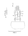
- FIG. 3 is a fragmentary cross-sectional view of the invention illustrating a remote activation device associated with the triggering means.
- the invention denoted generally by reference numeral 10 , is shown mounted within an inner surface of standard oil field piping (referenced generally as “A”).
- the device 10 comprises a triggering mechanism 12 comprised of a first end defining a rod 14 engaged with a well head (referenced as “B” positioned above ground level “C”), and triggering means 16 integrally formed at a second end.
- the triggering means 16 is composed of material that will melt from the temperature of intense fires or break if stressed.
- the rod 14 is formed of resilient material such as cast iron.
- a plunger 18 comprised of a rod 20 and a plug 22 is attached at a first end to the triggering mechanism 12 contiguous the triggering means 16 .
- the plug 22 is defined at a second end of the plunger 18 , and has an outer panel 24 and an inner panel 26 .
- the outer panel 24 has a sloping surface generally hemispherical in appearance, and is tapered from the outer perimeter of the rod 20 to a circular perimeter planer surface 28 defining the outer perimeter of the plug 22 . It should be recognized that the elevation of the outer panel 24 is not limited to any particular angle of slope.
- the slope of the inner panel 26 is also generally domed-shaped in appearance.
- a guide 30 having an annular flange 32 is mounted to the inner surface of the piping.
- a generally cylindrical case 34 with a bore 36 therethrough is formed through a central portion of the guide 30 positioned for receiving the rod 20 of the plunger 18 .
- a valve seat 38 having a first section defining an upper interior planer surface 40 and a second section defining a lower interior planer surface 42 , and a passage 44 defined therethrough to allow the flow of oil or gas, is mounted to the inner surface of the piping.
- the valve seat 38 is positioned so that it is in substantial alignment with the guide 30 .
- the upper interior planer surface 40 is smaller in diameter and concentrically located with respect to the lower interior planer surface 42 .
- the lower interior planer surface 42 is tapered downwardly.
- the rod 20 of the plunger 18 aligns through the bore 36 of the guide 30 and the passage 44 of the valve seat 38 .
- the plug 22 is aligned below the valve seat 38 .
- a spring 46 is mounted along an edge formed within the piping.
- the plug 22 mounts on the spring 46 .
- the triggering mechanism 12 and the plunger 18 are pressed downwardly by the well head, and in turn compress the spring 46 downwardly.
- the valve seat 38 is kept in the open position, allowing the normal flow of oil.
- FIG. 2 illustrates the movement of the spring 46 after the destruction of the triggering means 16 . Further fuel flow is prevented and the fire stopped.
- the triggering mechanism 12 may be integrally formed with a remote sensor 48 .
- a remote transmitter 50 communicating with the sensor 48 causing the destruction of the triggering means and closing the flow of oil.
- the sensor 48 and the transmitter 50 are well known in the prior art, and will not be further described.
Landscapes
- Life Sciences & Earth Sciences (AREA)
- Engineering & Computer Science (AREA)
- Geology (AREA)
- Mining & Mineral Resources (AREA)
- Physics & Mathematics (AREA)
- Environmental & Geological Engineering (AREA)
- Fluid Mechanics (AREA)
- General Life Sciences & Earth Sciences (AREA)
- Geochemistry & Mineralogy (AREA)
- Safety Valves (AREA)
Abstract
Description
Claims (3)
Priority Applications (1)
| Application Number | Priority Date | Filing Date | Title |
|---|---|---|---|
| US13/905,199 US8607872B1 (en) | 2013-05-30 | 2013-05-30 | Fire prevention blow-out valve |
Applications Claiming Priority (1)
| Application Number | Priority Date | Filing Date | Title |
|---|---|---|---|
| US13/905,199 US8607872B1 (en) | 2013-05-30 | 2013-05-30 | Fire prevention blow-out valve |
Publications (1)
| Publication Number | Publication Date |
|---|---|
| US8607872B1 true US8607872B1 (en) | 2013-12-17 |
Family
ID=49725617
Family Applications (1)
| Application Number | Title | Priority Date | Filing Date |
|---|---|---|---|
| US13/905,199 Expired - Fee Related US8607872B1 (en) | 2013-05-30 | 2013-05-30 | Fire prevention blow-out valve |
Country Status (1)
| Country | Link |
|---|---|
| US (1) | US8607872B1 (en) |
Cited By (2)
| Publication number | Priority date | Publication date | Assignee | Title |
|---|---|---|---|---|
| US10370928B2 (en) * | 2013-05-30 | 2019-08-06 | Schlumberger Technology Corporation | Structure with feed through |
| CN116411872A (en) * | 2023-04-04 | 2023-07-11 | 中海油田服务股份有限公司 | Fusing type bidirectional stop valve |
Citations (21)
| Publication number | Priority date | Publication date | Assignee | Title |
|---|---|---|---|---|
| US1911323A (en) * | 1932-11-26 | 1933-05-30 | Herbert C Otis | Apparatus for controlling oil wells |
| US3120267A (en) * | 1960-12-05 | 1964-02-04 | Jersey Prod Res Co | Fluid flow control in wells |
| US3653439A (en) * | 1970-06-01 | 1972-04-04 | Schlumberger Technology Corp | Subsurface safety valve |
| US3747618A (en) | 1971-08-13 | 1973-07-24 | R Boes | Automatic shut-off valve system |
| US3815675A (en) * | 1972-05-22 | 1974-06-11 | Exxon Production Research Co | Wireline operated subsurface safety valve |
| US3847216A (en) * | 1973-10-29 | 1974-11-12 | Varco Int | Well safety valve having mechanism shielded from fluid flow |
| US3853175A (en) * | 1971-11-30 | 1974-12-10 | Abegg & Reinhold Co | Remotely operated well safety valves |
| US3861464A (en) * | 1973-10-29 | 1975-01-21 | Varco Int | Safety valve for wells |
| US3916992A (en) * | 1972-05-12 | 1975-11-04 | Varco Int | Remotely operated well safety valves |
| US3987846A (en) | 1975-07-03 | 1976-10-26 | Exxon Production Research Company | Wellhead shut-off valve |
| US3990508A (en) * | 1972-05-12 | 1976-11-09 | Varco International, Inc. | Remotely operated well safety valves |
| US4109713A (en) | 1977-03-25 | 1978-08-29 | Clow Joseph Kenton | Pumping well blow-out preventer |
| US4316506A (en) | 1979-11-01 | 1982-02-23 | Lizzy Emergency Systems, Inc. | Oil well blow-out safety system |
| US4901617A (en) * | 1989-03-24 | 1990-02-20 | Malone Kenneth M | Hand-held percussion instrument |
| US4944350A (en) * | 1985-10-18 | 1990-07-31 | Schlumberger Technology Corporation | Tool for closing a well tubing |
| US5404953A (en) | 1992-10-16 | 1995-04-11 | Norsk Hydro A.S. | Blow-out prevention device for shutting off an annulus between a drill column and a well wall when drilling for oil or gas |
| US5771974A (en) | 1994-11-14 | 1998-06-30 | Schlumberger Technology Corporation | Test tree closure device for a cased subsea oil well |
| US6435282B1 (en) * | 2000-10-17 | 2002-08-20 | Halliburton Energy Services, Inc. | Annular flow safety valve and methods |
| US7114563B2 (en) * | 2004-04-16 | 2006-10-03 | Rose Lawrence C | Tubing or drill pipe conveyed downhole tool system with releasable wireline cable head |
| US7409999B2 (en) | 2004-07-30 | 2008-08-12 | Baker Hughes Incorporated | Downhole inflow control device with shut-off feature |
| US7588084B2 (en) * | 2002-10-24 | 2009-09-15 | Welltec A/S | Method for releasing cables from an attached well tool and apparatus for exercising the method |
-
2013
- 2013-05-30 US US13/905,199 patent/US8607872B1/en not_active Expired - Fee Related
Patent Citations (21)
| Publication number | Priority date | Publication date | Assignee | Title |
|---|---|---|---|---|
| US1911323A (en) * | 1932-11-26 | 1933-05-30 | Herbert C Otis | Apparatus for controlling oil wells |
| US3120267A (en) * | 1960-12-05 | 1964-02-04 | Jersey Prod Res Co | Fluid flow control in wells |
| US3653439A (en) * | 1970-06-01 | 1972-04-04 | Schlumberger Technology Corp | Subsurface safety valve |
| US3747618A (en) | 1971-08-13 | 1973-07-24 | R Boes | Automatic shut-off valve system |
| US3853175A (en) * | 1971-11-30 | 1974-12-10 | Abegg & Reinhold Co | Remotely operated well safety valves |
| US3916992A (en) * | 1972-05-12 | 1975-11-04 | Varco Int | Remotely operated well safety valves |
| US3990508A (en) * | 1972-05-12 | 1976-11-09 | Varco International, Inc. | Remotely operated well safety valves |
| US3815675A (en) * | 1972-05-22 | 1974-06-11 | Exxon Production Research Co | Wireline operated subsurface safety valve |
| US3847216A (en) * | 1973-10-29 | 1974-11-12 | Varco Int | Well safety valve having mechanism shielded from fluid flow |
| US3861464A (en) * | 1973-10-29 | 1975-01-21 | Varco Int | Safety valve for wells |
| US3987846A (en) | 1975-07-03 | 1976-10-26 | Exxon Production Research Company | Wellhead shut-off valve |
| US4109713A (en) | 1977-03-25 | 1978-08-29 | Clow Joseph Kenton | Pumping well blow-out preventer |
| US4316506A (en) | 1979-11-01 | 1982-02-23 | Lizzy Emergency Systems, Inc. | Oil well blow-out safety system |
| US4944350A (en) * | 1985-10-18 | 1990-07-31 | Schlumberger Technology Corporation | Tool for closing a well tubing |
| US4901617A (en) * | 1989-03-24 | 1990-02-20 | Malone Kenneth M | Hand-held percussion instrument |
| US5404953A (en) | 1992-10-16 | 1995-04-11 | Norsk Hydro A.S. | Blow-out prevention device for shutting off an annulus between a drill column and a well wall when drilling for oil or gas |
| US5771974A (en) | 1994-11-14 | 1998-06-30 | Schlumberger Technology Corporation | Test tree closure device for a cased subsea oil well |
| US6435282B1 (en) * | 2000-10-17 | 2002-08-20 | Halliburton Energy Services, Inc. | Annular flow safety valve and methods |
| US7588084B2 (en) * | 2002-10-24 | 2009-09-15 | Welltec A/S | Method for releasing cables from an attached well tool and apparatus for exercising the method |
| US7114563B2 (en) * | 2004-04-16 | 2006-10-03 | Rose Lawrence C | Tubing or drill pipe conveyed downhole tool system with releasable wireline cable head |
| US7409999B2 (en) | 2004-07-30 | 2008-08-12 | Baker Hughes Incorporated | Downhole inflow control device with shut-off feature |
Cited By (2)
| Publication number | Priority date | Publication date | Assignee | Title |
|---|---|---|---|---|
| US10370928B2 (en) * | 2013-05-30 | 2019-08-06 | Schlumberger Technology Corporation | Structure with feed through |
| CN116411872A (en) * | 2023-04-04 | 2023-07-11 | 中海油田服务股份有限公司 | Fusing type bidirectional stop valve |
Similar Documents
| Publication | Publication Date | Title |
|---|---|---|
| US9382778B2 (en) | Breaking of frangible isolation elements | |
| US20060042803A1 (en) | Sprinkler head shut-off tool | |
| KR101295042B1 (en) | Fire extinguisher with fire detecition tube | |
| US10316979B2 (en) | Ceramic rupture dome for pressure control | |
| US8607872B1 (en) | Fire prevention blow-out valve | |
| CN104548453B (en) | The container value of suspension type fire-smothering gear | |
| KR20170027224A (en) | Smart valve with gas pressure regulator | |
| CN207454852U (en) | A kind of double-direction relief valve | |
| US9464760B2 (en) | Gas filling nozzle with safety function | |
| KR101605105B1 (en) | Auto-Acting Quick Closing Valve | |
| US5143110A (en) | Seismic gas shutoff valve | |
| CN110529604A (en) | Gas control valve and its control method, beverage aerating device | |
| US2927592A (en) | Shock actuated valve | |
| US5449015A (en) | Shock-activated shut-off valve | |
| CN105107128A (en) | Temperature sensing self opening and closing fire extinguishing device | |
| KR102043164B1 (en) | Fire Suppression Starter System | |
| KR20210112194A (en) | firing pin loading device for gas fire extinguisher solenoid valve | |
| US1782020A (en) | Head for puncturing closure disks | |
| KR101537108B1 (en) | sprinkler of plunger integral | |
| US20100096022A1 (en) | Safety shutoff valve | |
| US4535796A (en) | Seismic actuated shut-off valve | |
| CN104548443B (en) | A kind of temperature control pilot-operated type spray head | |
| KR200485396Y1 (en) | Safety device for gas container | |
| CN105257902B (en) | Hydrant valve door lock | |
| CN206655968U (en) | A kind of gas valve with fire-proof function |
Legal Events
| Date | Code | Title | Description |
|---|---|---|---|
| STCF | Information on status: patent grant |
Free format text: PATENTED CASE |
|
| REMI | Maintenance fee reminder mailed | ||
| FEPP | Fee payment procedure |
Free format text: SURCHARGE FOR LATE PAYMENT, MICRO ENTITY (ORIGINAL EVENT CODE: M3554) |
|
| MAFP | Maintenance fee payment |
Free format text: PAYMENT OF MAINTENANCE FEE, 4TH YEAR, MICRO ENTITY (ORIGINAL EVENT CODE: M3551) Year of fee payment: 4 |
|
| FEPP | Fee payment procedure |
Free format text: MAINTENANCE FEE REMINDER MAILED (ORIGINAL EVENT CODE: REM.); ENTITY STATUS OF PATENT OWNER: MICROENTITY |
|
| LAPS | Lapse for failure to pay maintenance fees |
Free format text: PATENT EXPIRED FOR FAILURE TO PAY MAINTENANCE FEES (ORIGINAL EVENT CODE: EXP.); ENTITY STATUS OF PATENT OWNER: MICROENTITY |
|
| STCH | Information on status: patent discontinuation |
Free format text: PATENT EXPIRED DUE TO NONPAYMENT OF MAINTENANCE FEES UNDER 37 CFR 1.362 |
|
| FP | Lapsed due to failure to pay maintenance fee |
Effective date: 20211217 |