US8605344B2 - Optical reflecting mirror, and optical scanner and image forming apparatus including same - Google Patents
Optical reflecting mirror, and optical scanner and image forming apparatus including same Download PDFInfo
- Publication number
- US8605344B2 US8605344B2 US12/473,845 US47384509A US8605344B2 US 8605344 B2 US8605344 B2 US 8605344B2 US 47384509 A US47384509 A US 47384509A US 8605344 B2 US8605344 B2 US 8605344B2
- Authority
- US
- United States
- Prior art keywords
- optical
- reflecting mirror
- end portions
- center portion
- optical reflecting
- Prior art date
- Legal status (The legal status is an assumption and is not a legal conclusion. Google has not performed a legal analysis and makes no representation as to the accuracy of the status listed.)
- Expired - Fee Related, expires
Links
- 230000003287 optical effect Effects 0.000 title claims abstract description 210
- 230000002787 reinforcement Effects 0.000 description 14
- 239000003086 colorant Substances 0.000 description 10
- 230000007547 defect Effects 0.000 description 6
- 238000000034 method Methods 0.000 description 6
- 230000008901 benefit Effects 0.000 description 5
- 239000000463 material Substances 0.000 description 5
- 230000002411 adverse Effects 0.000 description 3
- 238000012986 modification Methods 0.000 description 3
- 230000004048 modification Effects 0.000 description 3
- 238000011144 upstream manufacturing Methods 0.000 description 3
- 230000015572 biosynthetic process Effects 0.000 description 2
- 239000003795 chemical substances by application Substances 0.000 description 2
- 230000003247 decreasing effect Effects 0.000 description 1
- 230000003467 diminishing effect Effects 0.000 description 1
- 230000000694 effects Effects 0.000 description 1
- 238000010438 heat treatment Methods 0.000 description 1
- 238000010348 incorporation Methods 0.000 description 1
- 238000003825 pressing Methods 0.000 description 1
- 230000001737 promoting effect Effects 0.000 description 1
- 230000001902 propagating effect Effects 0.000 description 1
- 239000000126 substance Substances 0.000 description 1
- 230000001360 synchronised effect Effects 0.000 description 1
Images


Classifications
-
- G—PHYSICS
- G02—OPTICS
- G02B—OPTICAL ELEMENTS, SYSTEMS OR APPARATUS
- G02B17/00—Systems with reflecting surfaces, with or without refracting elements
- G02B17/02—Catoptric systems, e.g. image erecting and reversing system
- G02B17/06—Catoptric systems, e.g. image erecting and reversing system using mirrors only, i.e. having only one curved mirror
- G02B17/0605—Catoptric systems, e.g. image erecting and reversing system using mirrors only, i.e. having only one curved mirror using two curved mirrors
- G02B17/0621—Catoptric systems, e.g. image erecting and reversing system using mirrors only, i.e. having only one curved mirror using two curved mirrors off-axis or unobscured systems in which not all of the mirrors share a common axis of rotational symmetry, e.g. at least one of the mirrors is warped, tilted or decentered with respect to the other elements
-
- G—PHYSICS
- G02—OPTICS
- G02B—OPTICAL ELEMENTS, SYSTEMS OR APPARATUS
- G02B5/00—Optical elements other than lenses
- G02B5/08—Mirrors
-
- G—PHYSICS
- G02—OPTICS
- G02B—OPTICAL ELEMENTS, SYSTEMS OR APPARATUS
- G02B26/00—Optical devices or arrangements for the control of light using movable or deformable optical elements
- G02B26/08—Optical devices or arrangements for the control of light using movable or deformable optical elements for controlling the direction of light
- G02B26/10—Scanning systems
- G02B26/12—Scanning systems using multifaceted mirrors
- G02B26/125—Details of the optical system between the polygonal mirror and the image plane
-
- G—PHYSICS
- G02—OPTICS
- G02B—OPTICAL ELEMENTS, SYSTEMS OR APPARATUS
- G02B7/00—Mountings, adjusting means, or light-tight connections, for optical elements
- G02B7/18—Mountings, adjusting means, or light-tight connections, for optical elements for prisms; for mirrors
- G02B7/182—Mountings, adjusting means, or light-tight connections, for optical elements for prisms; for mirrors for mirrors
-
- H—ELECTRICITY
- H04—ELECTRIC COMMUNICATION TECHNIQUE
- H04N—PICTORIAL COMMUNICATION, e.g. TELEVISION
- H04N1/00—Scanning, transmission or reproduction of documents or the like, e.g. facsimile transmission; Details thereof
- H04N1/04—Scanning arrangements, i.e. arrangements for the displacement of active reading or reproducing elements relative to the original or reproducing medium, or vice versa
- H04N1/113—Scanning arrangements, i.e. arrangements for the displacement of active reading or reproducing elements relative to the original or reproducing medium, or vice versa using oscillating or rotating mirrors
- H04N1/1135—Scanning arrangements, i.e. arrangements for the displacement of active reading or reproducing elements relative to the original or reproducing medium, or vice versa using oscillating or rotating mirrors for the main-scan only
Definitions
- the present invention relates to a rectangular plate optical reflecting mirror in an optical scanner mounted on an image forming apparatus, such as a copier, a printer, or a facsimile.
- the optical scanner exposes a surface of an image bearing member with an optical beam (for example, laser beam) and scans the surface with the optical beam, the optical reflecting mirror reflecting the optical beam to guide the optical beam onto a surface to be scanned.
- the present invention relates to the optical scanner and the image forming apparatus including the optical reflecting mirror.
- an optical scanner that is used in a copier or a printer exposes a surface of an image bearing member, for example, a photosensitive drum or a surface to be scanned, to light while scanning the surface, and forms a predetermined electrostatic latent image on the surface of the photosensitive drum.
- an optical beam for example, a laser beam, emitted from a light source is deflected by an optical deflector in a main-scanning direction, and is sent to the surface to be scanned by an optical system member such as a optical reflecting mirror.
- the optical scanner includes a light source such as a laser diode.
- the laser beam emitted from the light source is incident on a polygonal mirror serving as the optical deflector.
- the polygonal mirror reflects the laser beam using a reflection surface, and deflects the laser beam in the main-scanning direction.
- the laser beam that is deflected in the main-scanning direction is deflected at a uniform velocity by an f ⁇ lens so as to be parallel to an axial direction of the photosensitive drum.
- the deflected laser beam is sent to the surface of the photosensitive drum via the optical reflecting mirror and an image is formed on the surface.
- the vibrations occurring in the optical scanner or propagating to the optical scanner may reach the optical member, for example, the lens or the optical reflecting mirror.
- the optical reflecting mirror vibrates, it is difficult to maintain the predetermined position and angle of the optical reflecting mirror. Accordingly, the optical axis of the optical beam may shift. As a result, the electrostatic latent image formed on the surface of the photosensitive drum may be adversely affected, thereby resulting in reduced image quality.
- An optical reflecting mirror disclosed in the above publication includes a reinforcement member bonded to one or both side surfaces extending in a longitudinal direction.
- the optical reflecting mirror disclosed in the publication includes the reinforcement member bonded to one or both surfaces extending in the longitudinal direction, this results in an increase in the weight and rigidity of the optical reflecting mirror.
- vibration of the optical reflecting mirror is decreased, and it reduces a defect from occurring as a result of a reduction in the flatness of the optical reflecting mirror.
- the vibration of the optical scanner with the plurality of vibration modes is not reduced.
- the optical reflecting mirror may resonate. Due to this, an image defect such as a lateral stripe may appear, and this may reduce the image quality.
- the flatness of the optical reflecting mirror may be determined in view of the flatness of the reinforcement member, or the optical reflecting mirror may be deformed when the reinforcement member is deformed due to changes in temperature and humidity. Accordingly, an image defect such as curvature of field may appear, and this may reduce the image quality. Accordingly, image formation with high image quality may not be provided.
- an advantage of the present invention is to provide a rectangular plate optical reflecting mirror which reflects an optical beam to guide the optical beam onto a surface to be scanned, the optical reflecting mirror having a rigidity that eliminates the necessity of using a reinforcement member, the reinforcement member being likely affected by material characteristic, capable of preventing resonance from occurring as a result of vibration with a plurality of vibration modes and capable of providing a high-quality image.
- Another advantage of the present invention is to provide an optical scanner and an image forming apparatus including the optical reflecting mirror.
- a rectangular plate optical reflecting mirror which reflects an optical beam onto a surface to be scanned.
- the optical reflecting mirror includes a center portion and end portions in a longitudinal direction.
- the center portion reflects the optical beam.
- the end portions are supported by a housing.
- the center portion has a greater thickness than that of both end portions.
- the center portion may protrude at a rear surface opposite to a reflection surface extending in the longitudinal direction, with respect to the both end portions.
- a rear surface opposite to a reflection surface may extend parallel to the reflection surface, and step portions may be provided between the center portion and the end portions.
- inclined surfaces may be provided at positions of the step portions such that the inclined surfaces extend to connect a flat surface of the center portion with flat surfaces of the end portions.
- curved surfaces may be provided at corners of the step portions.
- the end portions may be formed by cutting, such that the thickness of the end portions is smaller than the thickness of the center portion.
- an optical scanner includes a light source which emits an optical beam, an optical deflector which deflects the optical beam in a main-scanning direction, and a optical reflecting mirror which reflects the optical beam toward a surface to be scanned.
- the optical reflecting mirror includes a center portion and both end portions in a longitudinal direction. The center portion reflects the optical beam. The end portions are supported by a housing. The center portion has a greater thickness than that of the end portions.
- an image forming apparatus includes an optical scanner.
- the optical scanner includes a light source which emits an optical beam, an optical deflector which deflects the optical beam in a main-scanning direction, and a optical reflecting mirror which reflects the optical beam toward a surface to be scanned.
- the optical reflecting mirror includes a center portion and end portions in a longitudinal direction. The center portion reflects the optical beam. The end portions are supported by a housing. The center portion has a greater thickness than that of both end portions.
- the optical scanner includes the optical reflecting mirror and the image forming apparatus includes the optical scanner. Accordingly, high-performance optical scanner and image forming apparatus capable of providing high-quality images can be provided.
- FIG. 1 is a front view of a vertical section schematically showing an image forming apparatus including an optical scanner including an optical reflecting mirror according to an embodiment of the present invention
- FIG. 2 is a front view of a vertical section schematically showing the optical scanner of FIG. 1 ;
- FIG. 3 is a top view schematically showing the optical scanner of FIG. 2 ;
- FIG. 4 is a perspective view showing the optical reflecting mirror of FIG. 3 viewed from a rear view opposite to a reflection surface;
- FIG. 5 is a top view showing the optical reflecting mirror of FIG. 4 ;
- FIG. 6 is a perspective view showing a optical reflecting mirror according to another embodiment of the invention when viewed from a rear view opposite to a reflection surface;
- FIG. 7 is a perspective view showing a optical reflecting mirror according to a further embodiment of the invention when viewed from a rear view opposite to a reflection surface.
- Embodiments of the present invention will be described below with reference to FIGS. 1 to 7 .
- FIG. 1 is a front view of a vertical section schematically showing the image forming apparatus.
- the image forming apparatus is a color print type in which a toner image is transferred onto a sheet by an intermediate transfer belt.
- a sheet feed cassette 3 is located at a lower position in a main body 2 of an image forming apparatus 1 .
- sheets P such as cut paper, before printing, are stacked.
- the sheets P are separated and fed one at a time to an upper left side ( FIG. 1 ) of the sheet feed cassette 3 .
- the sheet feed cassette 3 can be horizontally pulled out from a front surface of the main body 2 .
- a first sheet conveying portion 4 is provided in the main body 2 at a left side of the sheet feed cassette 3 .
- the first sheet conveying portion 4 extends substantially vertically along a left surface of the main body 2 .
- the first sheet conveying portion 4 receives a sheet P fed from the sheet feed cassette 3 , and feeds the sheet P toward a vertically upper side along the left surface of the main body 2 to a secondary transfer portion 9 .
- a manual sheet feed portion 5 is located above the sheet feed cassette 3 at a right surface of the main body 2 , the right surface being opposite to the left surface along which the first sheet conveying portion 4 extends. Sheets having a type that is not suitable for storage in the sheet feed cassette 3 , e.g., heavy sheets or OHP sheets, which are manually fed one by one, are stacked on the manual sheet feed portion 5 .
- a second sheet conveying portion 6 is located at a left side of the manual sheet feed portion 5 .
- the second sheet conveying portion 6 is located directly above the sheet feed cassette 3 , substantially horizontally extends from the manual sheet feed portion 5 to the first sheet conveying portion 4 , and meets the first sheet conveying portion 4 .
- the second sheet conveying portion 6 receives a sheet P or the like fed from the manual sheet feed portion 5 , and feeds the sheet P substantially horizontally to the first sheet conveying portion 4 .
- the image forming apparatus 1 receives original image data from an external computer (not shown). Information with respect to the image data is sent to an optical scanner 20 located above the second sheet conveying portion 6 and which serves as exposure means. With the optical scanner 20 , a laser beam L which is controlled in accordance with the image data is emitted to image forming units 30 .
- An intermediate transfer belt 7 is provided above the image forming units 30 .
- the intermediate transfer belt 7 is an endless belt formed of an intermediate transfer member.
- the intermediate transfer belt 7 is wound around and supported by a plurality of rollers.
- the intermediate transfer belt 7 is rotated clockwise ( FIG. 1 ) by a driver (not shown).
- the four image forming units 30 are arranged in a so-called tandem form in which the image forming units 30 are located in a rotation direction of the intermediate transfer belt 7 , in a line from the upstream side to the downstream side in the rotation direction.
- the four image forming units 30 include: a yellow image forming unit 30 Y; a magenta image forming unit 30 M; a cyan image forming unit 30 C; and a black image forming unit 30 B in that order from the upstream side.
- the image forming units 30 are respectively supplied with developing agents (toners) by conveying means (not shown) from developing agent supply containers of the respective colors.
- developing agents toers
- Each image forming unit 30 forms an electrostatic latent image of an original image with a laser beam L emitted by the optical scanner 20 serving as the exposure means.
- a toner image is developed from this electrostatic latent image.
- the toner image is primarily transferred on a surface of the intermediate transfer belt 7 at a primary transfer portion 8 provided above each image forming unit 30 .
- the intermediate transfer belt 7 rotates, the toner image of each image forming unit 30 is transferred on the intermediate transfer belt 7 at a predetermined time. Accordingly, a color toner image, in which toner images of the four colors of yellow, magenta, cyan, and black are superposed on each other, is formed on the surface of the intermediate transfer belt 7 .
- the secondary transfer portion 9 is located at a position at which the intermediate transfer belt 7 reaches a sheet conveying path.
- the color toner image on the surface of the intermediate transfer belt 7 is transferred onto the sheet P at a secondary transfer nip portion provided at the secondary transfer portion 9 .
- the sheet P is fed by the first sheet conveying portion 4 so as to be synchronized with the secondary transfer operation.
- any residue substances such as toner remaining on the surface of the intermediate transfer belt 7 is cleaned up and recovered by a cleaner 10 for the intermediate transfer belt 7 .
- the cleaner 10 is located at a position upstream of the yellow image forming unit 30 Y in the rotation direction, for the intermediate transfer belt 7 .
- a fixer 11 is provided above the secondary transfer portion 9 .
- the sheet P which has an unfixed toner image at the secondary transfer portion 9 is sent to the fixer 11 .
- the toner image is fixed at the fixer 11 by heating and pressing the toner image with a heat roller and a pressure roller.
- a separator 12 is provided above the fixer 11 .
- the sheet P ejected from the fixer 11 is ejected to a sheet ejection portion 13 provided at an upper part of the image forming apparatus 1 through the separator 12 when duplex printing is not performed.
- An ejection port portion through which the sheet P is ejected from the separator 12 to the sheet ejection portion 13 , functions as a switchback portion 14 .
- the conveyance direction of the sheet P ejected from the fixer 11 is changed at the switchback portion 14 .
- the sheet P is fed through the separator 12 , a left side of the fixer 11 , and a left side of the secondary transfer portion 9 to a lower side, and is fed to the secondary transfer portion 9 again through the first sheet conveying portion 4 .
- FIG. 2 is a front view of a vertical section schematically showing the optical scanner.
- FIG. 3 is a top view schematically showing the optical scanner.
- the optical scanner 20 is designed to be mounted on the tandem image forming apparatus 1 including four photosensitive drums 31 , respectively corresponding to the four colors: yellow; magenta; cyan; and black. Similar to the image forming units 30 , some components of the optical scanner 20 have the reference characters of “Y”, “M”, “C”, and “B” of the four colors. In the following description, however, these reference characters are occasionally omitted unless these colors have to be particularly set forth.
- the optical scanner 20 includes a box-shaped housing 21 with an upper surface formed as an open part.
- An optical device is provided in the housing 21 .
- the optical device includes a light source 22 , an optical deflector 40 , an optical system 50 , and an optical sensor 23 .
- the light source 22 is provided at one end of the housing 21 .
- the optical scanner 20 corresponds to the four colors: yellow; magenta; cyan; and black. Hence, four light sources 22 for the respective colors are provided.
- Each light source 22 is a laser diode which emits an optical beam in a visible range, for example, a laser beam of about 670 nm.
- the optical deflector 40 is provided near the light sources 22 .
- the optical deflector 40 includes a polygonal mirror 41 and a motor 42 .
- the motor 42 rotationally drives the polygonal mirror 41 around an axis extending in a vertical direction ( FIG. 2 ).
- the polygonal mirror 41 has a regular polygonal shape with flat surfaces.
- the polygonal mirror 41 which rotates around the axis, has a plurality of reflection surfaces on the periphery thereof to reflect light.
- Laser beams LY, LM, LC, and LB emitted from the four light sources 22 are incident on the reflection surfaces on the periphery of the polygonal mirror 41 at angles that are slightly different from each other in a sub-scanning direction (up-down direction in FIG. 2 ).
- the polygonal mirror 41 reflects the laser beams by the reflection surfaces while rotating, so as to deflect the laser beams in the main-scanning direction (left-right direction in FIG. 3 ) and to guide the laser beams to another end of the housing 21 .
- the optical system 50 is provided in the housing 21 in a region in which the laser beams reflected by the optical deflector 40 propagate.
- the optical system 50 includes a first f ⁇ lens 51 , second f ⁇ lenses 52 , and optical reflecting mirrors 53 .
- the first f ⁇ lens 51 is located at a position at which the laser beams LY, LM, LC, and LB propagate immediately after the light beams LY, LM, LC, and LB are reflected by the optical deflector 40 .
- the first f ⁇ lens 51 is shared by the laser beams LY, LM, LC, and LB, and hence, a single first f ⁇ lens 51 is provided.
- the first f ⁇ lens 51 deflects the laser beams LY, LM, LC, and LB at a uniform velocity in the main-scanning direction.
- the first f ⁇ lens 51 slightly increases the angles of the laser beams LY, LM, LC, and LB in the sub-scanning direction while the incident angles of the laser beams LY, LM, LC, and LB to the polygonal mirror 41 and an adverse effect as a result of scanning, such as face tangle of the polygonal mirror 41 , are corrected.
- the yellow laser beam LY passing through the first f ⁇ lens 51 is reflected by a optical reflecting mirror 53 Ya located near an inner bottom surface of the housing 21 , and turned toward the first f ⁇ lens 51 . Then, the laser beam LY passes through a second f ⁇ lens 52 Y, and is reflected by a optical reflecting mirror 53 Yb arranged near an upper end of the housing 21 , and reaches a surface of a yellow photosensitive drum 31 Y which is the surface to be scanned, thereby forming an image on the surface.
- the magenta laser beam LM passing through the first f ⁇ lens 51 is reflected by a optical reflecting mirror 53 Ya located near the inner bottom surface of the housing 21 , and turned toward the first f ⁇ lens 51 , in a similar manner to the yellow laser beam LY. Then, the laser beam LM passes through a second f ⁇ lens 52 M, is reflected by a optical reflecting mirror 53 Mb arranged near the upper end of the housing 21 , and reaches a surface of a magenta photosensitive drum 31 M which is the surface to be scanned, thereby forming an image on the surface.
- the cyan laser beam LC passing through the first f ⁇ lens 51 is reflected by a optical reflecting mirror 53 Ca located near the inner bottom surface of the housing 21 substantially vertically upward, and then is reflected by a optical reflecting mirror 53 Cb arranged near the upper end of the housing 21 , and turned substantially horizontally toward the first f ⁇ lens 51 . Then, the laser beam LC passes through a second f ⁇ lens 52 C, is reflected by a optical reflecting mirror 53 Cc, and reaches a surface of a cyan photosensitive drum 31 C which is the surface to be scanned, thereby forming an image on the surface.
- the black laser beam LB passing through the first f ⁇ lens 51 directly passes through a second f ⁇ lens 52 B without being reflected by a optical reflecting mirror. Then, the laser beam LB is reflected by a optical reflecting mirror 53 B, and reaches a surface of a black photosensitive drum 31 B which is the surface to be scanned, thereby forming an image on the surface.
- the optical sensor 23 is located near the optical reflecting mirror 53 Ya and the second f ⁇ lens 52 M, at a position near the outside in the main-scanning direction.
- the optical sensor 23 receives light outside an effective exposure area of the surface to be scanned, from among the laser beams reflected by the polygonal mirror 41 of the optical deflector 40 .
- the laser beam received by the optical sensor 23 is reflected by a optical reflecting mirror 24 located near the second f ⁇ lens 52 B toward the optical sensor 23 .
- the optical sensor 23 is a synchronism sensor for detecting scanning timings of the laser beams LY, LM, LC, and LB of the four colors.
- the optical sensor 23 is called a beam detect (BD) sensor.
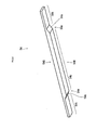
- FIG. 4 is a perspective view showing a optical reflecting mirror when viewed from a rear surface opposite to a reflection surface.
- FIG. 5 is a top view showing the optical reflecting mirror.
- Each optical reflecting mirror 53 extends straight in the main-scanning direction as shown in FIGS. 2 and 3 , and has a rectangular plate shape as shown in FIG. 4 . Both end portions in the main scanning direction shown in FIGS. 4 and 5 , that is, both end portions 53 t in a longitudinal direction of the optical reflecting mirror 53 are supported by the housing 21 .
- a center portion 53 u in the longitudinal direction of the optical reflecting mirror 53 has a greater thickness than that of the end portions 53 t as shown in FIGS. 4 and 5 .
- the center portion 53 u has the greater thickness than that of the end portions 53 t , at a rear surface 53 R opposite to a reflection surface 53 S extending in the longitudinal direction.
- the rear surface 53 R of the reflection surface 53 S extends parallel to the reflection surface 53 S, and step portions 53 w are provided between the center portion 53 u and the both end portions 53 t.
- the end portions 53 t of the optical reflecting mirror 53 are formed by cutting the optical reflecting mirror, which originally had the entire thickness of the center portion 53 u , and removing only areas A at the both end portions 53 t such that the end portions 53 t become thinner than the center portion 53 u.
- the thickness of the center portion 53 u is greater than the thickness of the both end portions 53 t , the thickness of the center portion 53 u can be increased as a single member without a reinforcement member being bonded to the optical reflecting mirror 53 . Accordingly, the rigidity of the optical reflecting mirror 53 can be increased, and its characteristic frequency can be set at a high value. Thus, the optical reflecting mirror 53 can resist the vibration with a plurality of vibration modes, thereby preventing resonance of the optical reflecting mirror 53 . Also, since no reinforcement member is bonded to the optical reflecting mirror 53 , the flatness of the optical reflecting mirror 53 is not adversely affected by the material characteristics of other members. Accordingly, an optical reflecting mirror 53 can be provided, which is capable of preventing an image defect such as a lateral stripe or curvature of the field from appearing, and capable of providing a high-quality image.
- the thickness of the center portion 53 u of the optical reflecting mirror 53 is greater than the end portions 53 t at the rear surface 53 R opposite to the reflection surface 53 S extending in the longitudinal direction. Accordingly, the rigidity of the center portion 53 u , which is an important portion for optical scanning, can be sufficiently increased while keeping the flatness of the reflection surface 53 S of the optical reflecting mirror highly precisely. Thus, an optical reflecting mirror 53 which promotes an increase in image quality can be provided.
- the rear surface 53 R opposite to the reflection surface 53 S extends parallel to the reflection surface 53 S, and step portions 53 w are provided between the center portion 53 u and the end portions 53 t . Accordingly, the center portion 53 u having the greater thickness and the end portions 53 t having the smaller thickness can be easily formed. Also, by adjusting the difference, the characteristic frequency of the optical reflecting mirror 53 can be changed as desired. Accordingly, an optical reflecting mirror 53 capable of effectively preventing resonance from occurring and capable of providing a high-quality image can be provided using a simple structure.
- the end portions 53 t are formed by cutting, so as to have a smaller thickness than that of the center portion 53 u , various shapes can be provided depending on the manner of cutting. Accordingly, when the optical reflecting mirror 53 is formed, the shape can be easily finely adjusted in accordance with the flatness and the characteristic frequency of the reflection surface 53 S. Thus, an optical reflecting mirror 53 having reflection surface 53 S with high-precision flatness and capable of effectively preventing resonance from occurring can be provided using a relatively simple procedure.
- the optical reflecting mirror 53 is provided in the optical scanner 20 , a high-performance optical scanner 20 can be provided, in which the optical reflecting mirror 53 has a rigidity that eliminates the necessity of using a reinforcement member, the reinforcement member likely being affected by the material characteristic, resonance can be prevented from occurring at the optical reflecting mirror 53 due to vibration of the housing vibrating with a plurality of vibration modes and a high-quality image can be provided.
- an image forming apparatus 1 in which the optical reflecting mirror 53 of the optical scanner 20 has a rigidity that eliminates the necessity of using a reinforcement member, the reinforcement member being likely affected by the material characteristic, resonance can be prevented from occurring at the optical reflecting mirror 53 due to vibration of the housing vibrating with a plurality of vibration modes, and a high-quality image can be provided.
- FIG. 6 is a perspective view showing the optical reflecting mirror when viewed from a rear surface opposite to a reflection surface.
- the basic structure of this embodiment is similar to that of the previous embodiment which has been described with reference to FIGS. 1 to 5 . Hence, the same reference characters are used for the components that are common to that embodiment, and redundant descriptions will be omitted.
- a optical reflecting mirror 54 has inclined surfaces 54 x at a rear surface 54 R opposite to a reflection surface 54 S, at positions of step portions 54 w provided between a center portion 54 u in a longitudinal direction and end portions 54 t in the longitudinal direction.
- the inclined surfaces 54 x are provided at the positions of the step portions 54 w such that the inclined surfaces 54 x extend to smoothly connect a flat surface of the center portion 54 u with flat surfaces of the end portions 54 t .
- a concentration of stress that is likely to occur at the corners of the step portions 54 w can be avoided.
- the flatness of the reflection surface 54 S of the optical reflecting mirror 54 can be maintained.
- an optical reflecting mirror 54 can be provided, which is capable of effectively preventing an image defect such as curvature of the field from appearing and capable of providing a higher-quality image.
- FIG. 7 is a perspective view showing the optical reflecting mirror when viewed from a rear surface opposite to a reflection surface.
- the basic structure of this embodiment is similar to that of the embodiment which has been described with reference to FIGS. 1 to 5 .
- the same reference characters will be used for the components that are common to that embodiment, and redundant descriptions will be omitted.
- a optical reflecting mirror 55 has curved surfaces 55 z at a rear surface 55 R opposite to a reflection surface 55 S, at positions of step portions 55 w provided between a center portion 55 u in a longitudinal direction and end portions 55 t in the longitudinal direction.
- the curved surfaces 55 z are provided in a curved manner at corner positions of the step portions 55 w , i.e., positions at which flat surfaces of the end portions 55 t are connected with flat surfaces orthogonal thereto such that the curved surfaces 55 z extend to smoothly connect these flat surfaces with each other.
- a concentration of stress that is likely to occur at the corners of the step portions 55 w can be avoided.
- an increase in weight of the optical reflecting mirror 55 can be prevented.
- the precision of the flatness of the reflection surface 55 S of the optical reflecting mirror 55 can be prevented from being reduced.
- the characteristic frequency can be set at a high value.
- an optical reflecting mirror 55 which is capable of effectively preventing an image defect such as curvature of the field from appearing, capable of preventing resonance from occurring at the optical reflecting mirror 55 as a result of vibration of the housing with a plurality of vibration modes, and capable of promoting image formation with high quality.
- the optical scanner 20 is mounted on the tandem color-print image forming apparatus 1 including the plurality of image forming units 30 arranged in a line in the rotation direction of the intermediate transfer belt 7 and being capable of forming an image by superposing a plurality of colors in the above-described embodiments, the optical scanner 20 is not limited to being mounted on this type of image forming apparatus.
- the optical scanner 20 can be mounted on a rotary-rack color-print image forming apparatus or a black-and-white image forming apparatus using only black toner.
Landscapes
- Physics & Mathematics (AREA)
- General Physics & Mathematics (AREA)
- Optics & Photonics (AREA)
- Engineering & Computer Science (AREA)
- Multimedia (AREA)
- Signal Processing (AREA)
- Laser Beam Printer (AREA)
- Facsimile Scanning Arrangements (AREA)
- Mechanical Optical Scanning Systems (AREA)
- Facsimile Heads (AREA)
Abstract
Description
Claims (4)
Applications Claiming Priority (2)
| Application Number | Priority Date | Filing Date | Title |
|---|---|---|---|
| JP2008201555A JP2010039157A (en) | 2008-08-05 | 2008-08-05 | Optical reflecting mirror, optical scanner and image forming apparatus including same |
| JP2008-201555 | 2008-08-05 |
Publications (2)
| Publication Number | Publication Date |
|---|---|
| US20100033775A1 US20100033775A1 (en) | 2010-02-11 |
| US8605344B2 true US8605344B2 (en) | 2013-12-10 |
Family
ID=41652657
Family Applications (1)
| Application Number | Title | Priority Date | Filing Date |
|---|---|---|---|
| US12/473,845 Expired - Fee Related US8605344B2 (en) | 2008-08-05 | 2009-05-28 | Optical reflecting mirror, and optical scanner and image forming apparatus including same |
Country Status (3)
| Country | Link |
|---|---|
| US (1) | US8605344B2 (en) |
| JP (1) | JP2010039157A (en) |
| CN (1) | CN101644829B (en) |
Families Citing this family (4)
| Publication number | Priority date | Publication date | Assignee | Title |
|---|---|---|---|---|
| JP5872306B2 (en) | 2012-01-30 | 2016-03-01 | 株式会社東芝 | Information processing apparatus, information processing method, and program |
| JP5907148B2 (en) * | 2013-11-28 | 2016-04-20 | コニカミノルタ株式会社 | Image forming apparatus |
| JP6241567B2 (en) * | 2015-02-20 | 2017-12-06 | 京セラドキュメントソリューションズ株式会社 | Optical scanning device and image forming apparatus |
| JP6708990B2 (en) * | 2016-06-27 | 2020-06-10 | 京セラドキュメントソリューションズ株式会社 | Optical scanning device and image forming apparatus including the optical scanning device |
Citations (6)
| Publication number | Priority date | Publication date | Assignee | Title |
|---|---|---|---|---|
| JPS5762002A (en) | 1980-10-01 | 1982-04-14 | Ricoh Co Ltd | Reflecting mirror device |
| JPH10282399A (en) | 1997-04-11 | 1998-10-23 | Ricoh Co Ltd | Optical fold mirror |
| US6404530B1 (en) | 1999-10-28 | 2002-06-11 | Asahi Kogaku Kogyo Kabushiki Kaisha | Scanning optical system |
| US20050057636A1 (en) * | 2003-09-16 | 2005-03-17 | Canon Kabushiki Kaisha | Optical scanning device and image forming apparatus using the same |
| US20060237638A1 (en) * | 2005-04-22 | 2006-10-26 | Lee Tae-Kyoung | Beam detector and light scanner unit having the same |
| US20100110517A1 (en) * | 2007-03-06 | 2010-05-06 | Shinichi Shikii | Optical scanning device and two-dimensional image display device using the same |
Family Cites Families (1)
| Publication number | Priority date | Publication date | Assignee | Title |
|---|---|---|---|---|
| JP2006030912A (en) * | 2004-07-21 | 2006-02-02 | Brother Ind Ltd | Image forming apparatus and scanning unit |
-
2008
- 2008-08-05 JP JP2008201555A patent/JP2010039157A/en active Pending
-
2009
- 2009-05-28 US US12/473,845 patent/US8605344B2/en not_active Expired - Fee Related
- 2009-07-13 CN CN2009101593198A patent/CN101644829B/en not_active Expired - Fee Related
Patent Citations (6)
| Publication number | Priority date | Publication date | Assignee | Title |
|---|---|---|---|---|
| JPS5762002A (en) | 1980-10-01 | 1982-04-14 | Ricoh Co Ltd | Reflecting mirror device |
| JPH10282399A (en) | 1997-04-11 | 1998-10-23 | Ricoh Co Ltd | Optical fold mirror |
| US6404530B1 (en) | 1999-10-28 | 2002-06-11 | Asahi Kogaku Kogyo Kabushiki Kaisha | Scanning optical system |
| US20050057636A1 (en) * | 2003-09-16 | 2005-03-17 | Canon Kabushiki Kaisha | Optical scanning device and image forming apparatus using the same |
| US20060237638A1 (en) * | 2005-04-22 | 2006-10-26 | Lee Tae-Kyoung | Beam detector and light scanner unit having the same |
| US20100110517A1 (en) * | 2007-03-06 | 2010-05-06 | Shinichi Shikii | Optical scanning device and two-dimensional image display device using the same |
Also Published As
| Publication number | Publication date |
|---|---|
| JP2010039157A (en) | 2010-02-18 |
| CN101644829B (en) | 2012-07-04 |
| US20100033775A1 (en) | 2010-02-11 |
| CN101644829A (en) | 2010-02-10 |
Similar Documents
| Publication | Publication Date | Title |
|---|---|---|
| JP5033548B2 (en) | Optical writing apparatus and image forming apparatus | |
| JP5899964B2 (en) | Optical writing apparatus and image forming apparatus | |
| JP4918439B2 (en) | Optical writing apparatus and image forming apparatus | |
| JP2018132637A (en) | Manufacturing method for optical scanning device, optical scanning device, and image forming apparatus | |
| JP4378193B2 (en) | Multi-beam optical scanning apparatus and image forming apparatus using the same | |
| US20110298882A1 (en) | Optical scanning apparatus and image forming apparatus including same | |
| US8605344B2 (en) | Optical reflecting mirror, and optical scanner and image forming apparatus including same | |
| JP2010039155A (en) | Optical scanner and image forming apparatus mounted with the same | |
| JP2010049061A (en) | Optical scanning apparatus and image forming apparatus using the same | |
| JP2020055195A (en) | Image forming device | |
| JP2009265403A (en) | Optical scanning apparatus and image forming apparatus using the same | |
| CN104216114B (en) | Optical scanner and the image processing system possessing this optical scanner | |
| JP5494281B2 (en) | Optical scanning apparatus and image forming apparatus | |
| JP2005091966A (en) | Optical scanning device and color image forming apparatus using the same | |
| JP4181765B2 (en) | Image forming apparatus | |
| JP5218095B2 (en) | Optical writing apparatus and image forming apparatus | |
| JP2010048956A (en) | Optical scanner of image forming apparatus | |
| JP5022945B2 (en) | Optical writing apparatus and image forming apparatus | |
| JP3686643B2 (en) | Optical scanning apparatus and image forming apparatus | |
| JP5321953B2 (en) | Optical scanning apparatus and image forming apparatus | |
| JP2006259673A (en) | Color light scanning apparatus and color image forming apparatus | |
| JP6834801B2 (en) | An optical scanning device and a color image forming apparatus provided with the optical scanning device. | |
| JP2017021311A (en) | Optical scanner and image forming apparatus | |
| JP2025142647A (en) | Optical scanning device and image forming device | |
| JP4761919B2 (en) | Scanning optical device |
Legal Events
| Date | Code | Title | Description |
|---|---|---|---|
| AS | Assignment |
Owner name: KYOCERA MITA CORPORATION,JAPAN Free format text: ASSIGNMENT OF ASSIGNORS INTEREST;ASSIGNORS:MIYANAGI, HIDETO;UCHIDA, KOUSUKE;REEL/FRAME:022769/0882 Effective date: 20090525 Owner name: KYOCERA MITA CORPORATION, JAPAN Free format text: ASSIGNMENT OF ASSIGNORS INTEREST;ASSIGNORS:MIYANAGI, HIDETO;UCHIDA, KOUSUKE;REEL/FRAME:022769/0882 Effective date: 20090525 |
|
| AS | Assignment |
Owner name: KYOCERA DOCUMENT SOLUTIONS INC., JAPAN Free format text: CHANGE OF NAME;ASSIGNOR:KYOCERA MITA CORPORATION;REEL/FRAME:028300/0460 Effective date: 20120401 |
|
| STCF | Information on status: patent grant |
Free format text: PATENTED CASE |
|
| FPAY | Fee payment |
Year of fee payment: 4 |
|
| FEPP | Fee payment procedure |
Free format text: MAINTENANCE FEE REMINDER MAILED (ORIGINAL EVENT CODE: REM.); ENTITY STATUS OF PATENT OWNER: LARGE ENTITY |
|
| LAPS | Lapse for failure to pay maintenance fees |
Free format text: PATENT EXPIRED FOR FAILURE TO PAY MAINTENANCE FEES (ORIGINAL EVENT CODE: EXP.); ENTITY STATUS OF PATENT OWNER: LARGE ENTITY |
|
| STCH | Information on status: patent discontinuation |
Free format text: PATENT EXPIRED DUE TO NONPAYMENT OF MAINTENANCE FEES UNDER 37 CFR 1.362 |
|
| FP | Lapsed due to failure to pay maintenance fee |
Effective date: 20211210 |