US8604402B2 - Spacecraft afterbody device - Google Patents
Spacecraft afterbody device Download PDFInfo
- Publication number
- US8604402B2 US8604402B2 US12/745,177 US74517708A US8604402B2 US 8604402 B2 US8604402 B2 US 8604402B2 US 74517708 A US74517708 A US 74517708A US 8604402 B2 US8604402 B2 US 8604402B2
- Authority
- US
- United States
- Prior art keywords
- vehicle
- spacecraft
- rocket engine
- plane
- cover elements
- Prior art date
- Legal status (The legal status is an assumption and is not a legal conclusion. Google has not performed a legal analysis and makes no representation as to the accuracy of the status listed.)
- Active, expires
Links
Images


Classifications
-
- B—PERFORMING OPERATIONS; TRANSPORTING
- B64—AIRCRAFT; AVIATION; COSMONAUTICS
- B64G—COSMONAUTICS; VEHICLES OR EQUIPMENT THEREFOR
- B64G1/00—Cosmonautic vehicles
- B64G1/14—Space shuttles
-
- F—MECHANICAL ENGINEERING; LIGHTING; HEATING; WEAPONS; BLASTING
- F02—COMBUSTION ENGINES; HOT-GAS OR COMBUSTION-PRODUCT ENGINE PLANTS
- F02K—JET-PROPULSION PLANTS
- F02K9/00—Rocket-engine plants, i.e. plants carrying both fuel and oxidant therefor; Control thereof
- F02K9/80—Rocket-engine plants, i.e. plants carrying both fuel and oxidant therefor; Control thereof characterised by thrust or thrust vector control
- F02K9/90—Rocket-engine plants, i.e. plants carrying both fuel and oxidant therefor; Control thereof characterised by thrust or thrust vector control using deflectors
-
- F—MECHANICAL ENGINEERING; LIGHTING; HEATING; WEAPONS; BLASTING
- F42—AMMUNITION; BLASTING
- F42B—EXPLOSIVE CHARGES, e.g. FOR BLASTING, FIREWORKS, AMMUNITION
- F42B10/00—Means for influencing, e.g. improving, the aerodynamic properties of projectiles or missiles; Arrangements on projectiles or missiles for stabilising, steering, range-reducing, range-increasing or fall-retarding
- F42B10/60—Steering arrangements
- F42B10/66—Steering by varying intensity or direction of thrust
Definitions
- This invention relates to a spacecraft afterbody device particularly designed to reduce the craft's aerodynamic drag during the atmospheric flight phase.
- a vehicle's resistance to movement due to its rear section is known as base drag.
- the fluid flows that have difficulty following the rear profiles of moving vehicles become turbulent behind the vehicle, which reduces pressure at the rear of the vehicle and creates a strong resistance to the vehicle's forward movement.
- Aerial vehicles propelled by jet engines present a jet pipe propelling nozzle and the jet engines only create a small amount of drag because the jet of ejected gases plays a role in the vehicle's aerodynamic profile.
- airbrake devices comprising flaps integrated in the aircraft jet engine's exhaust and being deployed to slow the aircraft down.
- Document U.S. Pat. No. 5,120,005 relates to such devices combining flaps opening behind the engine and flaps converging into the jet engine's exhaust flow to break the engine's thrust.
- document FR 2 705 739 describes a device for adjusting the diameter of the exhaust section of a rocket engine divergent nozzle to adapt the divergent nozzle to variable ambient conditions of flight.
- This device only changes the annular diameter of the exhaust and the shape of the walls facing the divergent nozzle along an axial symmetry in relation to the axis of the divergent nozzle.
- rocket propulsion therefore presents a problem in atmospheric flight because it generates a lot of drag due to the cross-section of the nozzle which is wide and forms a straight cut at the rear of the vehicle.
- the aim of the present invention is to produce an active and movable drag reduction device for spacecraft, installed to perform a function additional to the simple function of covering the rear of the vehicle in flight phases, such as atmospheric ascent, when the rocket engine is not in use.
- the device is installed in this way to take part in controlling the vehicle so as to add value to the device and to compensate for its weight by using it in braking and controlling the vehicle, in particular in the phases of return to atmospheric flight.
- the device of the invention has the advantage in this case of allowing a simplification and a weight reduction in the flight controls of a space plane since these flight controls no longer need to be designed to carry out the plane's aerodynamic braking.
- this invention provides an afterbody device for a spacecraft fitted with at least one rocket engine at the rear of the craft characterized in that it comprises at least one movable cover element designed to take a first position, masking and reducing the vehicle's rear drag, where it prolongs the vehicle's fuselage around at least one part of a rocket engine nozzle of the vehicle and extends beyond the rear of the vehicle's fuselage, and to take a second position fully deployed, increasing the vehicle's aerodynamic drag.
- the present invention thus realizes an active spacecraft drag reduction device, whose weight increase is compensated for by making it perform control assistance functions for most of the phases of flight outside the atmosphere and of return and, in particular, aerodynamic functions when the rocket engine is off, propulsive functions when the rocket engine is operating.
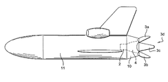
- FIG. 1 a schematic side view in cross-section of the rear of a spacecraft fitted with the device of the invention
- FIG. 2 a perspective view of a movable cover element of the device of the invention
- FIG. 3 a rear view of a spacecraft fitted with the device of the invention
- FIGS. 4A to 4E schematic side views of an aircraft fitted with the device of the invention according to several flight configurations
- FIG. 5 a cut-away side view of the space plane in FIG. 3 .
- the invention applies in particular to a spacecraft whose rocket engine is not used during atmospheric flight phases and creates significant aerodynamic drag, braking the vehicle and requiring an increase in the thrust necessary during take-off to the ascent of the vehicle in the atmosphere.
- the invention applies in particular to a vehicle such as a space shuttle in which the take-off and the atmospheric flight phase, or most of this phase, are performed with propulsion means other that the vehicle's rocket engine.
- a spacecraft that will be taken to a launch altitude by a carrier airplane, to a spacecraft propelled by jettisonable boosters for its take-off and atmospheric ascent, to a spacecraft such as a space-plane type of suborbital vehicle in which the first part of the trajectory is performed with an aeronautical type of propulsion using engines operating with oxygen from the air and foils, before switching to a rocket type of propulsion.
- the example shown in the figures corresponds to this last type of vehicle fitted with its own atmospheric engines 9 , represented in FIGS. 4A to 4E and fitted with at least one rocket engine 2 fitted with a nozzle 4 installed at the rear of the vehicle as shown in FIG. 1 .
- the first function of the spacecraft afterbody device is to mask nozzle 4 during the vehicle's atmospheric flight phases, when the rocket engine is not used.
- FIGS. 1 and 2 it comprises at least one cover element, an example of realization of which is shown in FIGS. 1 and 2 as a panel with a conical shape 3 .
- the cover element preferably comprises several panels 3 a , 3 b , 3 c , 3 d arranged so as to prolong the fuselage and which extend beyond the rear of the vehicle's fuselage to form a shell around the nozzle in a position A masking the nozzle.
- the cover element or elements can be moved separately and are designed to take first position A, masking and reducing the vehicle's rear drag, in which the cover is closed and prolongs the vehicle's fuselage around at least one part of the nozzle 4 of the vehicle's rocket engine and extends beyond the rear of the vehicle's fuselage, and to take a second position B fully deployed, increasing the vehicle's aerodynamic drag.
- the nozzle In this second position, the nozzle is uncovered to allow the rocket engine to operate and the propulsion jet to develop.
- FIG. 3 This position is shown in FIG. 3 in the context of an example of realization in which the device comprises four flaps 3 a , 3 b , 3 c , 3 d , two of which are deployed in a vertical plane and two are deployed in a horizontal plane.
- the cover elements 3 prolonging the vehicle's fuselage are hinged on the fuselage by rotating means of fastening 5 .
- Each element's hinge is installed such that it can rotate around an axis D as shown in FIG. 2 .
- cover elements 3 , 3 a , 3 b , 3 c , 3 d and make them movable with respect to the fuselage they are linked to this latter via an actuator 6 fixed onto the cover element by a first rotating link 7 and onto the fuselage by a second rotating link 8 .
- Rotating link 7 is offset perpendicularly to the element's axis of rotation D so that the panels can be moved.
- At least one part of cover element 3 , 3 a , 3 b , 3 c , 3 d is continuously movable, using actuator 6 , between the masking and drag reduction position A and the fully deployed position B, to intermediate positions C 1 , C 2 , C 3 for correcting the vehicle trajectory.
- the cover element comprises at least one generally upper panel 3 a and a generally lower panel 3 b designed to be moved separately and to achieve control of the vehicle during stalls and dives.
- the cover element comprises at least two generally lateral panels 3 c , 3 d designed to achieve control of the vehicle during a spin.
- the cover element comprises four panels 3 a , 3 b , 3 c , 3 d arranged as petals closing around nozzle 4 of the vehicle and allowing, through their deployment, the trajectory of the vehicle to be corrected, especially during its return into the atmosphere with rocket engine 2 not operating.
- FIGS. 4A to 4E is the case of a spacecraft made up of a space plane 11 fitted with atmospheric engines 9 for the atmospheric flight phases of the plane and fitted with an afterbody device comprising a cover element made up of two flaps 3 a , 3 b moving separately in a vertical plane to mask or uncover the rocket engine's nozzle.
- Such a configuration allows the implementation of a method for correcting the trajectory of a space plane 11 according to which the plane's trajectory is corrected by moving at least one cover element 3 a , 3 b of the device to intermediate positions C 1 , C 2 , C 3 between a position masking the plane's rocket engine nozzle A and a fully deployed position B for aerodynamically braking the plane.
- FIGS. 4A to 4E are described in the case of a cover in two parts, one upper and one lower, can be transposed to the case in which the device comprise four panels as shown in FIG. 5 , two panels 3 a , 3 b being moved separately in a vertical plane and two panels 3 c , 3 d being moved separately in a horizontal plane, these latter operating according to the principle of the invention adding a spin control.
- FIG. 4A corresponds to masking position A, which permits a decrease in base drag and a decrease in aerodynamic loads on the nozzle.
- FIG. 4A corresponds to masking position A, which permits a decrease in base drag and a decrease in aerodynamic loads on the nozzle.
- FIG. 4A corresponds to masking position A, which permits a decrease in base drag and a decrease in aerodynamic loads on the nozzle.
- FIG. 4A corresponds to masking position A, which permits a decrease in base drag and a decrease in aerodynamic loads on the nozzle.
- this position can be used during the recovery of the stage or booster or, in the case of a reusable launcher for the cruising phase of the return to the launch base.
- FIG. 4B corresponds to a contribution of panels 3 a , 3 b to high incidence flight.
- One is in a high incidence position at high altitude during a reentry, to increase drag and therefore increase the vehicle's deceleration in a still very rarefied atmosphere, whether this be for a space plane or for recovering a jettisonable propulsion stage or a reusable launcher.
- the high incidence position creates the aircraft's braking and the lower flap is used, in this configuration, to balance the position and stabilize the vehicle in the high incidence position by moving the center of thrust rearwards by air braking.
- the high incidence position is balanced by the opening or closing of the lower petal in intermediate positions between the masking position and the fully deployed position.
- FIG. 4C corresponds to air braking and stabilization positions around a zero incidence and/or zero slip attitude.
- This operating mode is used in particular during the final approach for a space plane or a reusable launcher. This is then a matter of controlling the gliding speed.
- More or less strong aerodynamic braking is achieved by opening the petals more or less between the position in FIG. 4A and that in FIG. 4C .
- It can also be used during the transonic passage upon reentry of a vehicle with zero lift gradient such as a jettisonable propulsion stage or a reusable launcher, or in the case of a straight-wing space plane.
- FIG. 4D corresponds to an intermediate position for increasing thrust in rocket mode.
- cover element 3 , 3 a , 3 b , 3 c , 3 d can be moved between masking and drag reduction position A and fully deployed position B, to intermediate positions for controlling the rocket engine.
- this position provides the vehicle with protection against the effects of jet breakup.
- the cover element comprises panels designed to form a screen that opposes the rocket engine's jet breakup and to refocus the jet to increase the engine's thrust.
- This position increases the thrust of the rocket engine by increasing the diameter of the nozzle's exhaust via an appropriate opening of the petals.
- the cover element can be moved in particular between masking and drag reduction position A and fully deployed position B, to positions for thermally protecting the rear of the vehicle.
- the petals then form a screen that protects the rear part of the vehicle from high altitude rocket engine jet breakup, at least the internal wall of the cover having high thermal resistance, either because the cover elements are made of a high thermal resistance material or because a coating resistant to the heat of the jet covers the internal surface facing the jet of the cover elements.
- This operating mode is applicable to a space plane, jettisonable boosters and reusable launchers during the rocket-propelled ascent in the upper atmosphere or in a vacuum.
- This operation corresponds to a method of optimizing the space plane's rocket engine according to which at least one cover element of the device is moved to positions assisting the rocket engine jet breakup, between a position masking a nozzle of a rocket engine of the plane A and a fully deployed position for aerodynamically braking the plane B.
- FIG. 4E corresponds to a position of vectorization of the rocket engine's thrust.
- This mode of operation therefore, of course, applies to a space plane, a jettisonable booster or a reusable launcher during the rocket-propelled ascent in the upper atmosphere or in a vacuum.
- the device of the invention allows the petals to be used to perform external aerodynamic functions when the rocket engine is not operating and propulsive functions when the rocket engine is operating.
- the device interacts with the vehicle's external aerodynamic flow whereas for the flight domain in which the rocket engine is operating, interaction with the rocket engine jet flow is desirable.
- these two flight domains cover a number of system functions, i.e. for the first domain reducing drag as shown in FIG. 4A , contributing to the longitudinal high incidence balance as shown in FIG. 4B , stabilization close to zero incidence and slip as shown in FIG. 4C during the transonic phase and aerodynamic braking during the approach with an intermediate position of the petals between the positions in FIGS. 4A and 4C .
- the functions covered by the device of the invention are increasing thrust by assisting the jet breakup at high altitude and/or thrust vectorization as shown in FIG. 4E , protecting certain afterbody parts from rocket engine jet breakup, examples in FIGS. 4D and 4E .
- the aircraft is fitted with complementary sub-assemblies comprising a set of actuators 6 fitted in an appropriate way between the fuselage and the petal panels.
- actuators which may be hydraulic or electric, are supplied in a known way with power and controlled by control devices.
- the complementary sub-assemblies further comprise an electronics assembly, not shown, for controlling the position of the petals, an electronics assembly that must be interfaced firstly to the aircraft flight program and secondly to an appropriate set of sensors able to define in real time the position of the aircraft in space and that of the panels.
- the complete cover or fairing is composed of 4 petals according to the example in FIG. 3 .
- petals are formed by panels 3 a to 3 d made of materials able to support the rocket engine's thermal flows, such as an inconel, or composite ceramics e.g. carbon/carbon protected against oxidation or carbon/SiC also protected.
- the petals formed by panels 3 a , 3 b moving along a vertical plane operate according to the positions described hereabove.
- the petals formed by panels 3 c , 3 d move along a horizontal plane and allow the aircraft's spin trajectory to be corrected, take part in braking in the fully deployed position or vectorize the rocket engine thrust in a horizontal plane.
- each petal comprises an articulated fastener 5 allowing a link with the rear of the space plane's fuselage.
- rocket engine 2 is inserted into the fuselage practically up to the exhaust section of nozzle 4 so also as to reduce aerodynamic drag, the rocket engine itself being a geometrically complex assembly likely to generate drag.
- the fuselage is prolonged by a tapered annular covering 10 to which the panels or petals 3 a to 3 d are connected.
- each petal also comprises a fastening point for an actuator 6 repeated on the space plane's fuselage such that the movement of actuator 6 allows a wider or narrower opening of the petal, as required.
- the shape of the panels forming the petals contributes in itself to the rigidity of these petals and to their resistance to the forces they are subject to.
- the invention therefore makes it possible to eliminate the rocket engine control devices and in particular the actuators and their power source, to reduce the thermal protection of the bottom of the vehicle,
- the invention is not limited to the example represented and in particular the cover element can have an oval cross-section if the spacecraft comprised two engines or more.
Landscapes
- Engineering & Computer Science (AREA)
- General Engineering & Computer Science (AREA)
- Chemical & Material Sciences (AREA)
- Aviation & Aerospace Engineering (AREA)
- Combustion & Propulsion (AREA)
- Mechanical Engineering (AREA)
- Remote Sensing (AREA)
- Physics & Mathematics (AREA)
- Fluid Mechanics (AREA)
- Toys (AREA)
- Transmission Devices (AREA)
- Automatic Assembly (AREA)
- Tires In General (AREA)
- Braking Arrangements (AREA)
Abstract
Description
Claims (14)
Applications Claiming Priority (4)
| Application Number | Priority Date | Filing Date | Title |
|---|---|---|---|
| FR07/59434 | 2007-11-29 | ||
| FR0759434 | 2007-11-29 | ||
| FR0759434A FR2924411B1 (en) | 2007-11-29 | 2007-11-29 | REAR DEVICE SPACE BODY |
| PCT/EP2008/066029 WO2009068488A1 (en) | 2007-11-29 | 2008-11-21 | Spacecraft afterbody device |
Publications (2)
| Publication Number | Publication Date |
|---|---|
| US20100327108A1 US20100327108A1 (en) | 2010-12-30 |
| US8604402B2 true US8604402B2 (en) | 2013-12-10 |
Family
ID=39595662
Family Applications (1)
| Application Number | Title | Priority Date | Filing Date |
|---|---|---|---|
| US12/745,177 Active 2030-08-16 US8604402B2 (en) | 2007-11-29 | 2008-11-21 | Spacecraft afterbody device |
Country Status (10)
| Country | Link |
|---|---|
| US (1) | US8604402B2 (en) |
| EP (1) | EP2222565B1 (en) |
| JP (2) | JP5677092B2 (en) |
| CN (1) | CN101910002B (en) |
| AU (1) | AU2008328888B2 (en) |
| CA (1) | CA2706988C (en) |
| FR (1) | FR2924411B1 (en) |
| RU (1) | RU2516923C2 (en) |
| TN (1) | TN2010000238A1 (en) |
| WO (1) | WO2009068488A1 (en) |
Cited By (3)
| Publication number | Priority date | Publication date | Assignee | Title |
|---|---|---|---|---|
| US20150344158A1 (en) * | 2013-02-06 | 2015-12-03 | Airbus Defence And Space Sas | Space aircraft |
| US10316796B2 (en) | 2013-07-26 | 2019-06-11 | Airbus Safran Launchers Sas | Combustion gas discharge nozzle for a rocket engine provided with a sealing device between a stationary part and a moving part of the nozzle |
| WO2019178156A1 (en) * | 2018-03-12 | 2019-09-19 | Blue Origin, Llc | Rocket tank liquid level determination, and associated systems and methods |
Families Citing this family (16)
| Publication number | Priority date | Publication date | Assignee | Title |
|---|---|---|---|---|
| FR2924411B1 (en) * | 2007-11-29 | 2010-02-12 | Astrium Sas | REAR DEVICE SPACE BODY |
| ES2350429B1 (en) * | 2009-05-28 | 2011-11-18 | Airbus Operations, S.L. | TAIL CONE OF AN AIRCRAFT WITH FLAVABLE MOVABLE CARENA |
| FR2954275B1 (en) * | 2009-12-22 | 2012-01-13 | Astrium Sas | ULTRA-RAPID AIR VEHICLE AND ASSOCIATED AIR LOCOMOTION METHOD |
| RU2479469C1 (en) * | 2011-08-25 | 2013-04-20 | Николай Николаевич Рябуха | Gliding spaceship (versions) with folding nose cone and method of controlling its descent to airfield |
| CN102941927B (en) * | 2012-11-30 | 2015-06-17 | 中国航天空气动力技术研究院 | Axial-symmetry blunt body returner |
| FR3004167B1 (en) | 2013-04-05 | 2015-07-10 | Astrium Sas | DEVICE FOR CONTROLLING THE SPEED OF A SPATIAL AIRCRAFT DURING THE TRANSITION OF A SPATIAL FLIGHT PHASE TO AN AERONAUTICAL FLIGHT PHASE AND THE TRANSITION METHOD THEREOF |
| JP6670676B2 (en) * | 2016-05-19 | 2020-03-25 | 株式会社Ihi | Flying object |
| CN109579637B (en) * | 2018-12-07 | 2023-04-18 | 中国人民解放军国防科技大学 | Missile attitude control mechanism without control surface |
| CN110758730B (en) * | 2019-10-23 | 2022-04-22 | 南京航空航天大学 | Hypersonic aircraft and trajectory design thereof |
| CN111946461A (en) * | 2020-07-27 | 2020-11-17 | 山东鑫聚龙动力科技集团有限公司 | Wing shaft for aerospace engine and manufacturing process thereof |
| CN112009669B (en) * | 2020-08-11 | 2022-01-18 | 湖北航天技术研究院总体设计所 | Aircraft deceleration method and device based on air rudder |
| CN112046791B (en) * | 2020-08-27 | 2022-01-18 | 航天科工空间工程发展有限公司 | Return type freight aircraft |
| CN112455699B (en) * | 2020-11-13 | 2024-01-02 | 中国航空工业集团公司沈阳飞机设计研究所 | High-fusion aircraft rear body |
| CN114572381A (en) * | 2022-04-19 | 2022-06-03 | 中国商用飞机有限责任公司 | Tail cone with speed reducing assembly and airplane provided with tail cone |
| CN114962079B (en) * | 2022-08-01 | 2022-11-15 | 北京凌空天行科技有限责任公司 | Rocket nozzle extension structure |
| CN115388721B (en) * | 2022-10-26 | 2022-12-20 | 中国航空工业集团公司沈阳空气动力研究所 | Control device for drag reduction and thrust augmentation of bottom of carrier rocket |
Citations (17)
| Publication number | Priority date | Publication date | Assignee | Title |
|---|---|---|---|---|
| US2926491A (en) * | 1958-08-25 | 1960-03-01 | Orenda Engines Ltd | Actuating means for variable nozzles |
| DE1288447B (en) | 1963-02-06 | 1969-01-30 | Reiniger Kurt | Space glider |
| US3432125A (en) | 1966-07-18 | 1969-03-11 | Gen Dynamics Corp | Stowable aft fairing for a reusable rocket |
| GB1243641A (en) | 1968-06-27 | 1971-08-25 | Imp Metal Ind Kynoch Ltd | Improvements in rocket motor exhaust nozzle assemblies |
| US4411399A (en) * | 1981-09-29 | 1983-10-25 | The Boeing Company | Retractable nozzle fairing system for aeroplane center boost engine |
| EP0273850A2 (en) | 1986-12-29 | 1988-07-06 | United Technologies Corporation | Bodies with reduced base drag |
| US5120005A (en) * | 1990-09-14 | 1992-06-09 | General Electric Company | Exhaust flap speedbrake |
| DE4101960A1 (en) | 1991-01-24 | 1992-07-30 | Rheinmetall Gmbh | Guided missile structure - has inflatable air-bag at rear end which reduces air resistance and increases range of missile |
| FR2705739A1 (en) | 1993-05-28 | 1994-12-02 | Europ Propulsion | Rocket engine nozzle with selectively reduced output section. |
| US5871173A (en) | 1995-10-13 | 1999-02-16 | Gec-Marconi Limited | Drag-producing aerodynamic device |
| US6297486B1 (en) * | 1996-10-09 | 2001-10-02 | Rafael Armament Development Authority Ltd. | Base drag reducing device |
| US6723972B2 (en) * | 2000-12-22 | 2004-04-20 | Lockheed Martin Corporation | Method and apparatus for planar actuation of a flared surface to control a vehicle |
| US6745979B1 (en) | 2002-10-22 | 2004-06-08 | Zhuo Chen | Spacecraft and aerospace plane having scissors wings |
| US6926345B2 (en) | 2002-09-20 | 2005-08-09 | The Regents Of The University Of California | Apparatus and method for reducing drag of a bluff body in ground effect using counter-rotating vortex pairs |
| US20060150612A1 (en) | 2005-01-12 | 2006-07-13 | Honeywell International Inc. | Thrust vector control |
| US7997205B2 (en) * | 2009-05-08 | 2011-08-16 | Raytheon Company | Base drag reduction fairing |
| US8312813B2 (en) * | 2009-07-31 | 2012-11-20 | Raytheon Company | Deployable fairing and method for reducing aerodynamic drag on a gun-launched artillery shell |
Family Cites Families (12)
| Publication number | Priority date | Publication date | Assignee | Title |
|---|---|---|---|---|
| US3289974A (en) * | 1964-01-02 | 1966-12-06 | Trw Inc | Manned spacecraft with staged re-entry |
| DE2452053A1 (en) * | 1974-11-02 | 1976-05-06 | Dornier Gmbh | DEVICE FOR LAUNCHING ROCKET-PROPELLED AIRCRAFT |
| JPS60237147A (en) * | 1984-05-09 | 1985-11-26 | Toru Fujii | Tailless system control of jet aircraft |
| JPH0455196A (en) * | 1990-06-21 | 1992-02-21 | Mitsubishi Heavy Ind Ltd | Body flap for spaceshuttle |
| JP2739271B2 (en) * | 1992-10-09 | 1998-04-15 | 防衛庁技術研究本部長 | Flying object |
| RU2015080C1 (en) * | 1992-11-03 | 1994-06-30 | Местон Вячеслав Александрович | Space vehicle and emergency crew safety system |
| RU2142058C1 (en) * | 1997-11-18 | 1999-11-27 | Ермишин Александр Викторович | Detonation combustion pulse-jet engine |
| US6612522B1 (en) * | 1998-03-17 | 2003-09-02 | Starcraft Boosters, Inc. | Flyback booster with removable rocket propulsion module |
| RU2130407C1 (en) * | 1998-04-14 | 1999-05-20 | Анакин Анатолий Тимофеевич | Flying vehicle with mixed power plant |
| JP2001206298A (en) * | 2000-01-28 | 2001-07-31 | Fuji Heavy Ind Ltd | Aerospacecraft |
| RU2312795C2 (en) * | 2005-09-15 | 2007-12-20 | Открытое акционерное общество Таганрогский авиационный научно-технический комплекс им. Г.М. Бериева | Flying vehicle-convertiplane-amphibian (versions) |
| FR2924411B1 (en) * | 2007-11-29 | 2010-02-12 | Astrium Sas | REAR DEVICE SPACE BODY |
-
2007
- 2007-11-29 FR FR0759434A patent/FR2924411B1/en active Active
-
2008
- 2008-11-21 EP EP08853499.5A patent/EP2222565B1/en active Active
- 2008-11-21 RU RU2010126506/11A patent/RU2516923C2/en not_active IP Right Cessation
- 2008-11-21 CA CA2706988A patent/CA2706988C/en active Active
- 2008-11-21 JP JP2010535344A patent/JP5677092B2/en active Active
- 2008-11-21 WO PCT/EP2008/066029 patent/WO2009068488A1/en not_active Ceased
- 2008-11-21 CN CN200880123440.9A patent/CN101910002B/en not_active Expired - Fee Related
- 2008-11-21 US US12/745,177 patent/US8604402B2/en active Active
- 2008-11-21 AU AU2008328888A patent/AU2008328888B2/en not_active Ceased
-
2010
- 2010-05-28 TN TN2010000238A patent/TN2010000238A1/en unknown
-
2014
- 2014-10-30 JP JP2014221313A patent/JP2015051766A/en active Pending
Patent Citations (17)
| Publication number | Priority date | Publication date | Assignee | Title |
|---|---|---|---|---|
| US2926491A (en) * | 1958-08-25 | 1960-03-01 | Orenda Engines Ltd | Actuating means for variable nozzles |
| DE1288447B (en) | 1963-02-06 | 1969-01-30 | Reiniger Kurt | Space glider |
| US3432125A (en) | 1966-07-18 | 1969-03-11 | Gen Dynamics Corp | Stowable aft fairing for a reusable rocket |
| GB1243641A (en) | 1968-06-27 | 1971-08-25 | Imp Metal Ind Kynoch Ltd | Improvements in rocket motor exhaust nozzle assemblies |
| US4411399A (en) * | 1981-09-29 | 1983-10-25 | The Boeing Company | Retractable nozzle fairing system for aeroplane center boost engine |
| EP0273850A2 (en) | 1986-12-29 | 1988-07-06 | United Technologies Corporation | Bodies with reduced base drag |
| US5120005A (en) * | 1990-09-14 | 1992-06-09 | General Electric Company | Exhaust flap speedbrake |
| DE4101960A1 (en) | 1991-01-24 | 1992-07-30 | Rheinmetall Gmbh | Guided missile structure - has inflatable air-bag at rear end which reduces air resistance and increases range of missile |
| FR2705739A1 (en) | 1993-05-28 | 1994-12-02 | Europ Propulsion | Rocket engine nozzle with selectively reduced output section. |
| US5871173A (en) | 1995-10-13 | 1999-02-16 | Gec-Marconi Limited | Drag-producing aerodynamic device |
| US6297486B1 (en) * | 1996-10-09 | 2001-10-02 | Rafael Armament Development Authority Ltd. | Base drag reducing device |
| US6723972B2 (en) * | 2000-12-22 | 2004-04-20 | Lockheed Martin Corporation | Method and apparatus for planar actuation of a flared surface to control a vehicle |
| US6926345B2 (en) | 2002-09-20 | 2005-08-09 | The Regents Of The University Of California | Apparatus and method for reducing drag of a bluff body in ground effect using counter-rotating vortex pairs |
| US6745979B1 (en) | 2002-10-22 | 2004-06-08 | Zhuo Chen | Spacecraft and aerospace plane having scissors wings |
| US20060150612A1 (en) | 2005-01-12 | 2006-07-13 | Honeywell International Inc. | Thrust vector control |
| US7997205B2 (en) * | 2009-05-08 | 2011-08-16 | Raytheon Company | Base drag reduction fairing |
| US8312813B2 (en) * | 2009-07-31 | 2012-11-20 | Raytheon Company | Deployable fairing and method for reducing aerodynamic drag on a gun-launched artillery shell |
Non-Patent Citations (1)
| Title |
|---|
| International Search Report and Written Opinion for Application No. PCT/EP2008/066029, dated Dec. 16, 2008. |
Cited By (4)
| Publication number | Priority date | Publication date | Assignee | Title |
|---|---|---|---|---|
| US20150344158A1 (en) * | 2013-02-06 | 2015-12-03 | Airbus Defence And Space Sas | Space aircraft |
| US10316796B2 (en) | 2013-07-26 | 2019-06-11 | Airbus Safran Launchers Sas | Combustion gas discharge nozzle for a rocket engine provided with a sealing device between a stationary part and a moving part of the nozzle |
| WO2019178156A1 (en) * | 2018-03-12 | 2019-09-19 | Blue Origin, Llc | Rocket tank liquid level determination, and associated systems and methods |
| US12313025B2 (en) | 2018-03-12 | 2025-05-27 | Blue Origin Manufacturing, LLC | Rocket tank liquid level determination, and associated systems and methods |
Also Published As
| Publication number | Publication date |
|---|---|
| RU2010126506A (en) | 2012-01-10 |
| CA2706988A1 (en) | 2009-06-04 |
| EP2222565B1 (en) | 2017-05-03 |
| TN2010000238A1 (en) | 2011-11-11 |
| RU2516923C2 (en) | 2014-05-20 |
| AU2008328888A1 (en) | 2009-06-04 |
| FR2924411A1 (en) | 2009-06-05 |
| CN101910002A (en) | 2010-12-08 |
| JP2011504847A (en) | 2011-02-17 |
| US20100327108A1 (en) | 2010-12-30 |
| AU2008328888B2 (en) | 2013-10-31 |
| FR2924411B1 (en) | 2010-02-12 |
| JP5677092B2 (en) | 2015-02-25 |
| WO2009068488A1 (en) | 2009-06-04 |
| EP2222565A1 (en) | 2010-09-01 |
| JP2015051766A (en) | 2015-03-19 |
| CA2706988C (en) | 2016-03-08 |
| CN101910002B (en) | 2014-07-30 |
Similar Documents
| Publication | Publication Date | Title |
|---|---|---|
| US8604402B2 (en) | Spacecraft afterbody device | |
| US6454216B1 (en) | Reusable booster for the first stage of a launcher | |
| US11649073B2 (en) | Control surfaces for use with high speed vehicles, and associated systems and methods | |
| US4650139A (en) | Aerospike for attachment to space vehicle system | |
| EP0928269B1 (en) | Vehicle rotation and control mechanism | |
| WO2013039426A1 (en) | Gliding spacecraft with folding nose fairing (variants) and method for controlling the return thereof to the landing field | |
| US20090242690A1 (en) | Ducted propulsion vector system | |
| US6616092B1 (en) | Reusable flyback rocket booster and method for recovering same | |
| US6076771A (en) | System and method for controlling a re-entry vehicle | |
| US20240199237A1 (en) | Launch system and method | |
| JP2024513940A (en) | a non-axisymmetric heat shield, a nozzle at least partially defined by the heat shield, an engine including the nozzle, and a vehicle including the engine | |
| US8226044B2 (en) | Device for reducing aerodynamic drag of a vehicale | |
| US4790499A (en) | Aerospike for attachment to space vehicle system | |
| US9102395B2 (en) | Multifunctional propulsive system for an airplane | |
| US10815010B2 (en) | High altitude air launched rocket | |
| KR20150094606A (en) | Combined steering and drag-reduction device | |
| EP3013681B1 (en) | Improved airship | |
| Wilhite et al. | Advanced technologies for rocket single-stage-to-orbit vehicles | |
| CN105228900A (en) | Apparatus for controlling the speed of a space shuttle during transition from an aerospace phase to an aeronautical phase and associated transition method | |
| JP2024511567A (en) | Atmospheric re-entry landing gear for rocket stages and method for re-entering the atmosphere for rocket stages | |
| RU2019107051A (en) | ACCELERATION PLANE-CARRIER (OPTIONS) | |
| JPH08333000A (en) | Space shuttle wing fairing device |
Legal Events
| Date | Code | Title | Description |
|---|---|---|---|
| AS | Assignment |
Owner name: ASTRIUM SAS, FRANCE Free format text: ASSIGNMENT OF ASSIGNORS INTEREST;ASSIGNOR:PRAMPOLINI, MARCO;REEL/FRAME:024931/0273 Effective date: 20100623 |
|
| STCF | Information on status: patent grant |
Free format text: PATENTED CASE |
|
| FPAY | Fee payment |
Year of fee payment: 4 |
|
| AS | Assignment |
Owner name: ASTRIUM SAS, FRANCE Free format text: ADDRESS CHANGE;ASSIGNOR:ASTRIUM SAS;REEL/FRAME:046009/0719 Effective date: 20140721 |
|
| AS | Assignment |
Owner name: AIRBUS DEFENCE AND SPACE SAS, FRANCE Free format text: CHANGE OF NAME;ASSIGNOR:ASTRIUM;REEL/FRAME:046774/0727 Effective date: 20140721 |
|
| AS | Assignment |
Owner name: AIRBUS SAFRAN LAUNCHERS, FRANCE Free format text: CHANGE OF NAME;ASSIGNOR:AIRBUS DEFENCE AND SPACE SAS;REEL/FRAME:047173/0214 Effective date: 20160630 |
|
| AS | Assignment |
Owner name: AIRBUS SAFRAN LAUNCHERS SAS, FRANCE Free format text: ADDRESS CHANGE;ASSIGNOR:AIRBUS SAFRAN LAUNCHERS SAS;REEL/FRAME:048476/0624 Effective date: 20181023 |
|
| AS | Assignment |
Owner name: ARIANEGROUP SAS, FRANCE Free format text: CHANGE OF NAME;ASSIGNOR:AIRBUS SAFRAN LAUNCHERS SAS;REEL/FRAME:049413/0026 Effective date: 20170801 |
|
| MAFP | Maintenance fee payment |
Free format text: PAYMENT OF MAINTENANCE FEE, 8TH YEAR, LARGE ENTITY (ORIGINAL EVENT CODE: M1552); ENTITY STATUS OF PATENT OWNER: LARGE ENTITY Year of fee payment: 8 |
|
| MAFP | Maintenance fee payment |
Free format text: PAYMENT OF MAINTENANCE FEE, 12TH YEAR, LARGE ENTITY (ORIGINAL EVENT CODE: M1553); ENTITY STATUS OF PATENT OWNER: LARGE ENTITY Year of fee payment: 12 |