US8603415B2 - Microchip - Google Patents
Microchip Download PDFInfo
- Publication number
- US8603415B2 US8603415B2 US12/644,259 US64425909A US8603415B2 US 8603415 B2 US8603415 B2 US 8603415B2 US 64425909 A US64425909 A US 64425909A US 8603415 B2 US8603415 B2 US 8603415B2
- Authority
- US
- United States
- Prior art keywords
- component
- collection
- separation portion
- microchip
- flow path
- Prior art date
- Legal status (The legal status is an assumption and is not a legal conclusion. Google has not performed a legal analysis and makes no representation as to the accuracy of the status listed.)
- Expired - Fee Related, expires
Links
Images


Classifications
-
- G—PHYSICS
- G01—MEASURING; TESTING
- G01N—INVESTIGATING OR ANALYSING MATERIALS BY DETERMINING THEIR CHEMICAL OR PHYSICAL PROPERTIES
- G01N33/00—Investigating or analysing materials by specific methods not covered by groups G01N1/00 - G01N31/00
- G01N33/48—Biological material, e.g. blood, urine; Haemocytometers
- G01N33/483—Physical analysis of biological material
- G01N33/487—Physical analysis of biological material of liquid biological material
- G01N33/49—Blood
- G01N33/491—Blood by separating the blood components
-
- G—PHYSICS
- G01—MEASURING; TESTING
- G01N—INVESTIGATING OR ANALYSING MATERIALS BY DETERMINING THEIR CHEMICAL OR PHYSICAL PROPERTIES
- G01N15/00—Investigating characteristics of particles; Investigating permeability, pore-volume or surface-area of porous materials
- G01N15/04—Investigating sedimentation of particle suspensions
- G01N15/042—Investigating sedimentation of particle suspensions by centrifuging and investigating centrifugates
-
- G—PHYSICS
- G01—MEASURING; TESTING
- G01N—INVESTIGATING OR ANALYSING MATERIALS BY DETERMINING THEIR CHEMICAL OR PHYSICAL PROPERTIES
- G01N15/00—Investigating characteristics of particles; Investigating permeability, pore-volume or surface-area of porous materials
- G01N15/04—Investigating sedimentation of particle suspensions
- G01N15/05—Investigating sedimentation of particle suspensions in blood
-
- G—PHYSICS
- G01—MEASURING; TESTING
- G01N—INVESTIGATING OR ANALYSING MATERIALS BY DETERMINING THEIR CHEMICAL OR PHYSICAL PROPERTIES
- G01N35/00—Automatic analysis not limited to methods or materials provided for in any single one of groups G01N1/00 - G01N33/00; Handling materials therefor
- G01N2035/00465—Separating and mixing arrangements
- G01N2035/00495—Centrifuges
Definitions
- the present invention relates to a microchip useful for the purpose of ⁇ -TAS (Micro Total Analysis System) suitably employed in biochemical tests such as of blood, in chemical synthesis, in environmental analysis, and the like.
- ⁇ -TAS Micro Total Analysis System
- microchip Various biochips and microchemical chips (hereinafter, generically referred to as “microchip”) have been proposed to enable feasible measurements.
- the microchip disclosed in Japanese Patent Laying-Open No. 2007-33225 includes a fluid circuit therein; constituted mainly of various portions such as a liquid reagent holding portion for holding a liquid reagent required to treat a sample (blood or the like) that is the target of testing/analysis, or for reaction with the sample; a quantification portion for quantifying the sample (or particular component in the sample) and/or the liquid reagent; a mixing portion mixing the sample (or particular component in the sample) with the liquid reagent; a detection portion for analyzing and/or examining the mixed liquid; and a minute flow path (for example, a width of approximately several hundred ⁇ m) appropriately connecting the portions.
- a liquid reagent holding portion for holding a liquid reagent required to treat a sample (blood or the like) that is the target of testing/analysis, or for reaction with the sample
- a quantification portion for quantifying the sample (or particular component in the sample) and/or the liquid reagent
- a mixing portion mixing the sample (or particular
- microchips including a fluid circuit allows the series of experiments and analytical operations required to be carried out at a laboratory to be conducted within a chip of several centimeters in square and having a thickness of several millimeters, various advantages can be offered such as reduction in the amount of sample and reagent required, lower cost, faster reaction rate, and allowing testing with high throughput. Moreover, the test results of the sample can be obtained without delay at the site where the sample was collected. Microchips have been employed suitably for biochemical examination such as blood testing and the like.
- a conventional microchip is disadvantageous in that, even if the blood is separated into blood cells and plasma by centrifugal operation, only one component of the blood, plasma for example, can be collected. Blood cells that are another component of blood could not be collected and measured at the same time. Therefore, in the case where the glucose level is to be examined to arrive at a diagnosis of diabetes, it is necessary to measure the amount of hemoglobin Alc (HbAlc) in the blood cell indicating the average glucose level over approximately three months in the past prior to the date of collecting the blood cell, and at the same time measure the amount of glucose in the blood plasma indicating the glucose level over several hours from the point of time of collecting the blood plasma.
- HbAlc hemoglobin Alc
- an object of the present invention is to provide a microchip allowing collection and quantification of a plurality of components in a specimen.
- the present invention provides a microchip including a separation portion separating a first component and a second component from a specimen containing first and second components, a first collection portion collecting the first component, a second collection portion collecting the second component, a first flow path guiding the first component from the separation portion to the first collection portion, and a second flow path guiding the second component from the separation portion to the second collection portion.
- each of the first and second flow paths preferably extends in a direction radiating from the center of centrifugal force applied to the microchip.
- the separation portion preferably includes a first separation portion separating at least a portion of the first component from the specimen, a second separation portion separating at least a portion of the second component from the specimen, and a third flow path guiding a portion of the first component and the second component of the specimen from the first separation portion to the second separation portion.
- the first flow path is located between the first separation portion and the first collection portion, and the second flow path is located between the second separation portion and the second collection portion.
- the first flow path and the third flow path may be partially shared. Furthermore, the second flow path and the third flow path may be partially shared.
- the present invention provides a microchip including a first separation portion separating at least a portion of a first component from a specimen containing first and second components, a second separation portion separating at least a portion of a second component from the specimen containing first and second components, and a flow path guiding a portion of the first component and the second component of the specimen from the first separation portion to the second separation portion.
- the first component is obtained by separating the first component from the first separation portion.
- the second component is obtained by separating the second component from the second separation portion.
- the microchip of the present invention preferably includes a first collection portion collecting the first component, a second collection portion collecting the second component, a first flow path guiding the first component from the first separation portion to the first collection portion, and a second flow path guiding the second component from the second separation portion to the second collection portion.
- each of the first and second flow paths preferably extends in a direction radiating from the center of centrifugal force applied to the microchip.
- the second separation portion, the second collection portion, the first separation portion and the first collection portion are preferably arranged in the cited order on concentric circles differing in the direction radiating from the center of centrifugal force.
- portion A and portion B are connected includes the case where portion A and portion B are directly connected physically, as well as the case where portion A and portion B are connected indirectly via a minute flow path (small flow path) and/or various functional portions.
- a fluid including at least two components such as blood can be completely divided into plasma and blood cells, and first and second components can be collected individually in synchronism with an operation that will be described afterwards.
- a plurality of predetermined items can be measured simultaneously through subsequent various processes.
- FIG. 1 is a schematic diagram representing a first embodiment of a microchip according to the present invention.
- FIG. 2 is a plan view representing an example of a microchip of the present invention.
- FIGS. 3-6 are diagrams showing steps of operations at the microchip of FIG. 2 .
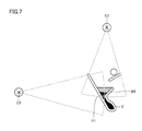
- FIG. 7 is an enlarged plan view of a first separation portion in the microchip of FIG. 2 .
- FIG. 8 is an enlarged plan view of a second separation portion in the microchip of FIG. 2 .
- FIG. 9 is a schematic diagram representing a second embodiment of a microchip according to the present invention.
- a microchip including an internal fluid circuit such as a microchip of the present invention
- the series of operations such as the quantification of a specimen and liquid reagent, the mixing of the specimen and liquid reagent, the transfer of the specimen, the liquid reagent and mixed liquid to each site in the fluid circuit can be carried out by applying centrifugal force towards the microchip in an appropriate direction.
- Application of the centrifugal force towards the microchip is carried out employing a centrifuge device having a microchip mount portion for mounting a microchip.
- the rotary motion to apply centrifugal force to the microchip is called “orbital motion”, whereas modifying the direction of the microchip to alter the direction of applying centrifugal force towards the microchip is referred to as a rotation movement turning on its own axis.
- FIG. 1 is a schematic diagram viewed in plane from above of a microchip 100 according to a first embodiment of the present invention.
- Microchip 100 of the present invention includes a separation portion 50 separating each of a first component and a second component from a specimen containing first and second components, a first collection portion 13 collecting the first component, and a second collection portion 11 a collecting the second component, a first flow path 12 guiding the first component from separation portion 50 to first collection portion 13 , and a second flow path 10 guiding the second component from separation portion 50 to second collection portion 11 a.
- microchip 100 shown in FIG. 1 will be described hereinafter based on an example in which a specimen containing first and second components is blood.
- the first component is blood cells
- the second component is blood plasma having a specific gravity lower than that of the first component.
- microchip 100 When blood is introduced to microchip 100 under the state shown in FIG. 1 , the introduced blood is transferred to separation portion 50 . Then, microchip 100 is rotated such that the centrifugal force is applied in the direction of arrow 81 in FIG. 1 . Accordingly, the blood is separated into blood cells that are the first component and blood plasma that is the second component by application of the centrifugal force.
- first flow path 12 and second flow path 10 each extend in a direction radiating from the center of the centrifugal force applied to the microchip (the direction including the direction of arrow 82 ). Therefore, the first and second components are collected at a first collection portion 13 and a second collection portion 11 a through first flow path 12 and second flow path 10 , respectively.
- FIG. 2 is a plan view of microchip 200 that is an example of a microchip of the present invention, viewed at the top. The functional portions that will be described afterwards are incorporated into one substrate. Microchip 200 shown in FIG. 2 will be described based on an example in which a specimen containing first and second components is blood.
- the first component is blood cells
- the second component is blood plasma having a specific gravity lower than that of the first component.
- a specimen inlet 1 is provided as an opening.
- a first separation portion 3 having a first inlet 2 , connected to specimen inlet 1 via a flow path 4 .
- a flow path wall 5 is provided between specimen inlet 1 and first separation portion 3 to run along the direction from second separation portion 8 to first separation portion 3 , as will be described afterwards.
- First separation portion 3 is connected to third flow path 6 via first inlet 2 .
- Third flow path 6 is connected to second separation portion 8 to via second inlet 7 .
- a fluid holding portion 9 is provided, communicating with first separation portion 3 and second separation portion 8 .
- first and second separation portions 3 and 8 are not adjacent, but spaced apart from each other.
- first and second separation portions 3 and 8 are connected, not in series, but in parallel via first and second inlets 2 and 7 .
- a portion of third flow path 6 constitutes a portion of first flow path 12 , and also a portion of second flow path 10 .
- Second separation portion 8 is also connected to second collection portions 11 a and 11 b via second flow path 10 from second inlet 7 .
- second collection portions 11 a and 11 b are arranged between first and second separation portions 3 and 8 such that blood plasma having a specific gravity lower than that of blood cells can be collected.
- Microchip 200 in FIG. 2 includes, but not limited to, two second collection portions 11 a and 11 b connected in series with second separation portion 8 .
- Microchip 200 may include three or more second collection portions.
- Second collection portions 11 a and 11 b each are connected to a mixing portion not shown where a reagent and blood plasma are mixed.
- Second collection portions 11 a and 11 b also have the measuring function to measure a predetermined amount by applying centrifugal force towards the collected blood plasma in a predetermined direction and cause the collected blood plasma to partially overflow from the second collection portion.
- the superfluous blood plasma is stored in a waste tank not shown through a waste opening.
- First separation portion 3 is connected to first collection portion 13 such that blood cells can be collected from first inlet 2 via first flow path 12 .
- First collection portion 13 is not disposed between first and second separation portions 3 and 8 where second collection portions 11 a and 11 b are arranged, and is disposed at the side opposite to where second collection portions 11 a and 11 b are located, based on first separation portion 3 .
- first collection portion 13 can measure a predetermined amount by applying centrifugal force in a predetermined direction with respect to the collected blood cells, and cause overflow from first collection portion 13 .
- First collection portion 13 is connected to a mixing portion to have the collected blood cells mixed with a reagent. The superfluous blood cells are stored in a waste tank not shown via the waste opening.
- FIGS. 3-6 represent the steps of the operation of microchip 200 shown in FIG. 2 .
- FIGS. 7 and 8 each are plan views enlarged from first separation portion 3 and second separation portion 8 in microchip 200 .
- microchip 200 is rotated at approximately 3,000 rpm with a first centrifugal center C 1 as the center, provided at the upper side in FIG. 3 (hereinafter, simply referred to as “upper side”; the same applies to FIGS. 4-6 , and likewise with other directions). Accordingly, centrifugal force is applied in a downward direction 91 in FIG. 3 (hereinafter, simply referred to as “downward”; the same applies to FIGS. 4-6 , and likewise with other directions).
- the whole blood is transferred into first separation portion 3 from first inlet 2 through flow path 4 , running along flow path wall 5 from specimen inlet 1 .
- first separation portion 3 The whole blood transferred to first separation portion 3 is divided by downward application of the centrifugal force into a blood plasma component (upper layer), and into a blood cell component (lower layer) having a larger specific gravity as compared to the blood plasma component (refer to FIGS. 3 and 7 ). Details of first separation portion 3 will be described afterwards.
- Second centrifugal center C 2 is set at a site 90° or within the range of 90° counterclockwise from first centrifugal center C 1 , when viewed in plane from the top of the microchip.
- the site corresponding to 90° counterclockwise from first centrifugal center C 1 is taken as second centrifugal center C 2 .
- Second centrifugal center C 2 is located at the left side of microchip 200 (refer to FIG. 4 ).
- a second wall face W 2 that is one wall constituting first inlet 2 is formed taking a shape running along a direction from first separation portion 3 to third flow path 6 or fluid holding portion 9 , or to second separation portion 8 , so that the entire blood plasma component and the portion of the blood cells are transferred smoothly to second separation portion 8 through third flow path 6 and fluid holding portion 9 .
- the entire blood plasma and the portion of blood cells separated in the first blood plasma and blood cell separation step are transferred to the side outer than the two concentric circles about second centrifugal center C 2 , where second collection portions 11 a and 11 b are arranged (the side farther away from second centrifugal center C 2 ). Accordingly, collection of the blood plasma and collection of blood cells can be carried out simultaneously in the collection and measuring step that will be described afterwards.
- Third centrifugal center C 3 is set at a site 90° or within the range of 90° clockwise from second centrifugal center C 2 , when viewed in plane from the top of the microchip.
- the site 90° clockwise from second centrifugal center C 2 is taken as third centrifugal center C 3 .
- Third centrifugal center C 3 is located at the upper side of microchip 200 (refer to FIG. 5 ).
- Fourth centrifugal center C 4 is set at a site 90° or within the range of 90° clockwise from third centrifugal center C 3 , when viewed in plane from the top of the microchip. For the sake of convenience, the sites 90° clockwise from third centrifugal center C 3 is taken as fourth centrifugal center C 4 . Fourth centrifugal center C 4 is located at the right side of microchip 200 (refer to FIG. 6 ).
- second collection portion 11 a is configured to measure a predetermined amount, allowing measuring of the predetermined amount.
- the overflowing blood plasma is transferred to second collection portion 11 b connected in series with second collection portion 11 a to be measured in a similar manner.
- the superfluous portion is transferred to a waste tank not shown through a waste outlet.
- a third wall face W 3 that is one wall constituting second inlet 7 is formed taking a shape running along a direction from second separation portion 8 to second collection portion 11 a such that blood plasma is transferred smoothly to second collection portion 11 a .
- the other fourth wall face W 4 constituting second inlet 7 is formed running along a direction from second separation portion 8 towards fluid holding portion 9 .
- first separation portion 3 is configured to also measure a predetermined amount, similar to second collection portions 11 a and 11 b, and can measure a predetermined amount by causing overflow from first collection portion 13 .
- the superfluous overflow is transferred to a waste tank not shown through a waste outlet, similar to second collection portions 11 a and 11 b.
- first wall face W 1 constituting one of the walls of first inlet 2 is formed taking a shape running along a direction from first separation portion 3 to first collection portion 13 such that blood cells can be smoothly transferred to first collection portion 13 .
- the blood plasma and blood cells collected at each collection portion are mixed with a prescribed reagent at a mixing portion for reaction.
- a measurement of comparison to a substance mixed with a reactive reagent can be achieved.
- First flow path 12 uniting first separation portion 3 and first collection portion 13 and second flow path 10 uniting second separation portion 8 and second collection portion 11 a are both arranged in a radiating direction from fourth centrifugal center C 4 . This arrangement allows first and second components to be collected simultaneously from each separation portion when the microchip is rotated about fourth centrifugal center C 4 .
- second separation portion 8 , second collection portions 11 a and 11 b, first separation portion 3 , and first collection portion 13 are arranged in the cited order on concentric circles differing in the direction radiating from fourth centrifugal center C 4 .
- second collection portion 11 a is provided on a concentric circle having a radius larger than that of the concentric circle about fourth centrifugal center C 4 where second separation portion 8 is located.
- first collection portion 13 is provided on a concentric circle having a radius larger than that of the concentric circle about fourth centrifugal center C 4 where first separation portion 3 is located. Accordingly, the blood cells and blood plasma can be transferred to first collection portion 13 and second collection portion 11 a, respectively, at the same time in the above-described collection and measuring step. Therefore, the blood plasma and blood cells can be mixed with individual reagents for reaction simultaneously by the process set forth above even though unseparated blood is introduced through only one specimen inlet 1 . Then, respective mixed liquids can be transferred to the detection portion to allow detection of HbAlc in the blood cells and glucose in the blood plasma, for example, at the same time.
- centrifugal force is applied about second centrifugal center C 2 in order to leave a predetermined amount of blood cells in first separation portion 3 .
- second separation portion 8 , second collection portions 11 a and 11 b, first separation portion 3 , and first collection portion 13 are arranged in the cited order on concentric circles differing in the direction radiating from fourth centrifugal center C 4 located at the side opposite to second centrifugal center C 2 with the microchip therebetween, in order to ensure transfer of the entire blood plasma and the portion of blood cells to second separation portion 8 .
- second wall face W 2 constituting second inlet 7 of second separation portion 8 is formed running along the direction from first separation portion 3 to second separation portion 8 or third flow path 6 .
- a first wall face W 1 constituting first inlet 2 is formed running along a direction from first separation portion 3 to first collection portion 13
- a third wall face W 3 of second inlet 7 is formed running along a direction from second separation portion 8 to second collection portion 11 a . This is to ensure the transfer from first separation portion 3 to first collection portion 13 , and from second separation portion 8 to second collection portion 11 a in the collection and measuring step.
- Fluid holding portion 9 and second separation portion 8 are arranged on different concentric circles about third centrifugal center C 3 .
- the radius of the concentric circle where second separation portion 8 is arranged is set larger than the radius of the concentric circle where fluid holding portion 9 is arranged (refer to FIG. 4 ).
- the entire blood plasma and a portion of blood cells can be held at the relevant holding portion when the centrifugal force is applied, as shown in FIG. 4 .
- the liquid can be transferred from fluid holding portion 9 to second separation portion 8 through second inlet 7 , as shown in FIG. 5 .
- First separation portion 3 shown in FIG. 7 is L-shaped (may take an inverted L shape in consideration of arrangement conditions).
- a vertex P 1 of the L shape is arranged such that the boundary between the blood plasma and blood cells is located at a circumference of a concentric circle about first centrifugal center C 1 , inner than the circle about first centrifugal center C 1 passing through the contacting point of the liquid level of the whole blood obtained by the liquid transfer step set forth above and the vertex (vertex P 1 of the L shape) of second wall face W 2 that is the inner wall closer to first centrifugal center C 1 , when centrifugal force is applied in the first blood plasma and blood cell separation step. Accordingly, the entire blood plasma and a portion of blood cells can be transferred from first separation portion 3 during the liquid transfer step to leave only the blood cells in first separation portion 3 . Therefore, only the blood cells can be transferred from first separation portion 3 to first collection portion 13 in the collection and measuring step.
- Second separation portion 8 shown in FIG. 8 takes an inversed L shape (may take an L shape in consideration of arrangement conditions).
- a vertex P 3 of the inversed L shape is arranged such that the boundary between the blood plasma and blood cells is located at an outer circumferential side of a circle about third centrifugal center C 3 passing through the contacting point of the liquid level of the entire blood plasma and a portion of blood cells obtained by the collection and weighing step and the vertex (vertex P 3 of the inversed L shape) of third wall face W 3 that is the inner wall closer to third centrifugal center C 3 . Accordingly, only the blood plasma can be transferred from second separation portion 8 in the collection and measuring step mode, allowing collection at second collection portion 11 a.
- FIG. 9 is a schematic plan view of a microchip 300 according to a second embodiment of the present invention.
- Microchip 300 includes a first separation portion 3 separating at least a portion of a first component from a specimen containing first and second components, a second separation portion 8 separating at least a portion of the second component from the specimen containing first and second components, a third flow path 6 guiding a portion of the first component and the second component of the specimen from first separation portion 3 to second separation portion 8 , a first collection portion 13 , a second collection portion 11 a , a first flow path 12 guiding the first component from first separation portion 3 to first collection portion 13 , and a second flow path 10 guiding the second component from second separation portion 8 to second collection portion 11 a .
- Microchip 300 is configured to obtain the first component by separating the first component from first separation portion 3 and the second component by separating the second component from the second separation portion.
- first flow path 12 guiding the first component from first separation portion 3 to first collection portion 13 and second flow path 10 guiding the second component from second separation portion 8 to second collection portion 11 a are both formed to run in the same direction relative to the direction of the centrifugal force applied in the collection and measuring step.
- Such a configuration allows simultaneous collection of first and second components separated in the collection and measuring step set forth above.
- the microchip of the present invention is also applicable to a fluid constituted of two or more components having different properties such as the hydrophilic property and hydrophobic property.
- the centrifugal force does not have to be intentionally applied for separation since separation is effected by the hydrophilic property and hydrophobic property itself.
- measurement will be allowed of a fluid having two or more components separated into two or more layers, each collected by a predetermined amount and made to react with a reaction agent or the like to detect a property corresponding to the reaction.
- the material of the substrate constituting the microchip of the present invention is not particularly limited.
- organic materials such polyethylene terephthalate (PET), polybutyrene terephthalate (PBT), polymethyl methacrylate (PMMA), polycarbonate (PC), polystyrene (PS), polypropylene (PP), polyethylene (PE), polyethylene naphthalate (PEN), poly arylate resin (PAR), acrylonitrile-butadiene-styrene resin (ABS), polyvinyl chloride resin (PVC), polymethylpentene resin (PMP), polybutadiene resin (PBD), biodegradable polymer (BP), cycloolefin polymer (COP), polydimethylsiloxane (PDMS); as well as inorganic materials such as silicon, glass and quartz may employed.
- organic materials such as polyethylene terephthalate (PET), polybutyrene terephthalate (PBT), polymethyl methacrylate (PMMA), polycarbonate (PC
- the method of forming a groove constituting a fluid circuit at the surface of the substrate is not particularly limited. Injection molding using a mold having a transfer structure, imprinting method, and the like can be cited. In the case where the substrate is formed based on an inorganic material, etching and the like may be employed.
Landscapes
- Health & Medical Sciences (AREA)
- Life Sciences & Earth Sciences (AREA)
- Chemical & Material Sciences (AREA)
- Engineering & Computer Science (AREA)
- Physics & Mathematics (AREA)
- Pathology (AREA)
- Biomedical Technology (AREA)
- General Health & Medical Sciences (AREA)
- General Physics & Mathematics (AREA)
- Immunology (AREA)
- Analytical Chemistry (AREA)
- Biochemistry (AREA)
- Hematology (AREA)
- Dispersion Chemistry (AREA)
- Ecology (AREA)
- Biophysics (AREA)
- Molecular Biology (AREA)
- Urology & Nephrology (AREA)
- Food Science & Technology (AREA)
- Medicinal Chemistry (AREA)
- Automatic Analysis And Handling Materials Therefor (AREA)
- Investigating Or Analysing Biological Materials (AREA)
Abstract
Description
Claims (8)
Applications Claiming Priority (2)
| Application Number | Priority Date | Filing Date | Title |
|---|---|---|---|
| JP2008325064A JP2010145314A (en) | 2008-12-22 | 2008-12-22 | Microchip |
| JP2008-325064 | 2008-12-22 |
Publications (2)
| Publication Number | Publication Date |
|---|---|
| US20100196204A1 US20100196204A1 (en) | 2010-08-05 |
| US8603415B2 true US8603415B2 (en) | 2013-12-10 |
Family
ID=42397879
Family Applications (1)
| Application Number | Title | Priority Date | Filing Date |
|---|---|---|---|
| US12/644,259 Expired - Fee Related US8603415B2 (en) | 2008-12-22 | 2009-12-22 | Microchip |
Country Status (2)
| Country | Link |
|---|---|
| US (1) | US8603415B2 (en) |
| JP (1) | JP2010145314A (en) |
Cited By (1)
| Publication number | Priority date | Publication date | Assignee | Title |
|---|---|---|---|---|
| US20120301908A1 (en) * | 2010-02-01 | 2012-11-29 | Eurotrol B.V. | Method for Determining the Reliability of a Device for Measuring the Concentration of a Substance in Whole Blood, Method for Treating Whole Blood, Container and Kit |
Families Citing this family (2)
| Publication number | Priority date | Publication date | Assignee | Title |
|---|---|---|---|---|
| JP5459265B2 (en) * | 2011-05-30 | 2014-04-02 | ブラザー工業株式会社 | Inspection target receptacle, liquid mixing system including the inspection target receptacle, and liquid mixing method using the liquid mixing system |
| JP5565398B2 (en) * | 2011-09-30 | 2014-08-06 | ブラザー工業株式会社 | Inspection target |
Citations (2)
| Publication number | Priority date | Publication date | Assignee | Title |
|---|---|---|---|---|
| US4788154A (en) * | 1985-12-20 | 1988-11-29 | Jean Guigan | Method and apparatus for obtaining and delivering a predetermined quantity of plasma from a blood sample for analysis purposes |
| JP2007033225A (en) | 2005-07-27 | 2007-02-08 | Matsushita Electric Ind Co Ltd | Rotational analysis device |
Family Cites Families (2)
| Publication number | Priority date | Publication date | Assignee | Title |
|---|---|---|---|---|
| FR2790682B1 (en) * | 1999-03-09 | 2001-05-11 | Biomerieux Sa | METHOD AND APPARATUS FOR TRANSFERRING A FLUID THROUGH SEVERAL CENTRIFUGATIONS |
| JP4752546B2 (en) * | 2006-03-03 | 2011-08-17 | パナソニック株式会社 | Centrifuge device and centrifuge method |
-
2008
- 2008-12-22 JP JP2008325064A patent/JP2010145314A/en active Pending
-
2009
- 2009-12-22 US US12/644,259 patent/US8603415B2/en not_active Expired - Fee Related
Patent Citations (2)
| Publication number | Priority date | Publication date | Assignee | Title |
|---|---|---|---|---|
| US4788154A (en) * | 1985-12-20 | 1988-11-29 | Jean Guigan | Method and apparatus for obtaining and delivering a predetermined quantity of plasma from a blood sample for analysis purposes |
| JP2007033225A (en) | 2005-07-27 | 2007-02-08 | Matsushita Electric Ind Co Ltd | Rotational analysis device |
Cited By (1)
| Publication number | Priority date | Publication date | Assignee | Title |
|---|---|---|---|---|
| US20120301908A1 (en) * | 2010-02-01 | 2012-11-29 | Eurotrol B.V. | Method for Determining the Reliability of a Device for Measuring the Concentration of a Substance in Whole Blood, Method for Treating Whole Blood, Container and Kit |
Also Published As
| Publication number | Publication date |
|---|---|
| JP2010145314A (en) | 2010-07-01 |
| US20100196204A1 (en) | 2010-08-05 |
Similar Documents
| Publication | Publication Date | Title |
|---|---|---|
| US8906323B2 (en) | Microchip | |
| JP5137012B2 (en) | Microchip | |
| JP4673149B2 (en) | Method of using microchip, microchannel, and microchip | |
| JP5423200B2 (en) | Analysis chip and sample analysis method | |
| US20090232708A1 (en) | Microchip | |
| US20130029361A1 (en) | Disc-shaped analysis chip | |
| CN103170378A (en) | Micro fluidic chip apparatus used for immunization analysis | |
| JP5728217B2 (en) | Microchip and inspection or analysis method using the same | |
| JP5736230B2 (en) | Microchip | |
| US8603415B2 (en) | Microchip | |
| JP2009287971A (en) | Microchip | |
| JP5137007B2 (en) | Microchip | |
| US20090291025A1 (en) | Microchip And Method Of Using The Same | |
| JP5172461B2 (en) | Microchip | |
| JP5137014B2 (en) | Microchip | |
| JP2008268198A (en) | Separation chip and separation method | |
| JP5077945B2 (en) | Microchip | |
| JP5137011B2 (en) | Microchip | |
| Gao et al. | Microchip technology applications for blood group analysis | |
| JP5964555B2 (en) | Microchip, and measurement system and measurement method using the same | |
| JP2009156682A (en) | Microchip with sealing film | |
| JP2009281869A (en) | Microchip | |
| JP2007333716A (en) | Separating/weighing chip, and method for using the same | |
| JP6049463B2 (en) | Microchip | |
| JP5173723B2 (en) | Microchip |
Legal Events
| Date | Code | Title | Description |
|---|---|---|---|
| AS | Assignment |
Owner name: ROHM CO., LTD., JAPAN Free format text: ASSIGNMENT OF ASSIGNORS INTEREST;ASSIGNOR:YAMAICHI, MASATO;REEL/FRAME:024032/0614 Effective date: 20100219 |
|
| STCF | Information on status: patent grant |
Free format text: PATENTED CASE |
|
| FEPP | Fee payment procedure |
Free format text: PAYER NUMBER DE-ASSIGNED (ORIGINAL EVENT CODE: RMPN); ENTITY STATUS OF PATENT OWNER: LARGE ENTITY Free format text: PAYOR NUMBER ASSIGNED (ORIGINAL EVENT CODE: ASPN); ENTITY STATUS OF PATENT OWNER: LARGE ENTITY |
|
| FPAY | Fee payment |
Year of fee payment: 4 |
|
| AS | Assignment |
Owner name: HORIBA, LTD., JAPAN Free format text: ASSIGNMENT OF ASSIGNORS INTEREST;ASSIGNOR:ROHM CO., LTD.;REEL/FRAME:049049/0016 Effective date: 20181203 |
|
| FEPP | Fee payment procedure |
Free format text: MAINTENANCE FEE REMINDER MAILED (ORIGINAL EVENT CODE: REM.); ENTITY STATUS OF PATENT OWNER: LARGE ENTITY |
|
| LAPS | Lapse for failure to pay maintenance fees |
Free format text: PATENT EXPIRED FOR FAILURE TO PAY MAINTENANCE FEES (ORIGINAL EVENT CODE: EXP.); ENTITY STATUS OF PATENT OWNER: LARGE ENTITY |
|
| STCH | Information on status: patent discontinuation |
Free format text: PATENT EXPIRED DUE TO NONPAYMENT OF MAINTENANCE FEES UNDER 37 CFR 1.362 |
|
| FP | Lapsed due to failure to pay maintenance fee |
Effective date: 20211210 |