US8597453B2 - Method for producing highly conductive sheet molding compound, fuel cell flow field plate, and bipolar plate - Google Patents
Method for producing highly conductive sheet molding compound, fuel cell flow field plate, and bipolar plate Download PDFInfo
- Publication number
- US8597453B2 US8597453B2 US11/293,541 US29354105A US8597453B2 US 8597453 B2 US8597453 B2 US 8597453B2 US 29354105 A US29354105 A US 29354105A US 8597453 B2 US8597453 B2 US 8597453B2
- Authority
- US
- United States
- Prior art keywords
- sheet
- resin
- resin mixture
- conductive filler
- flexible graphite
- Prior art date
- Legal status (The legal status is an assumption and is not a legal conclusion. Google has not performed a legal analysis and makes no representation as to the accuracy of the status listed.)
- Expired - Fee Related, expires
Links
Images


Classifications
-
- B—PERFORMING OPERATIONS; TRANSPORTING
- B29—WORKING OF PLASTICS; WORKING OF SUBSTANCES IN A PLASTIC STATE IN GENERAL
- B29C—SHAPING OR JOINING OF PLASTICS; SHAPING OF MATERIAL IN A PLASTIC STATE, NOT OTHERWISE PROVIDED FOR; AFTER-TREATMENT OF THE SHAPED PRODUCTS, e.g. REPAIRING
- B29C70/00—Shaping composites, i.e. plastics material comprising reinforcements, fillers or preformed parts, e.g. inserts
- B29C70/88—Shaping composites, i.e. plastics material comprising reinforcements, fillers or preformed parts, e.g. inserts characterised primarily by possessing specific properties, e.g. electrically conductive or locally reinforced
- B29C70/882—Shaping composites, i.e. plastics material comprising reinforcements, fillers or preformed parts, e.g. inserts characterised primarily by possessing specific properties, e.g. electrically conductive or locally reinforced partly or totally electrically conductive, e.g. for EMI shielding
-
- B—PERFORMING OPERATIONS; TRANSPORTING
- B29—WORKING OF PLASTICS; WORKING OF SUBSTANCES IN A PLASTIC STATE IN GENERAL
- B29C—SHAPING OR JOINING OF PLASTICS; SHAPING OF MATERIAL IN A PLASTIC STATE, NOT OTHERWISE PROVIDED FOR; AFTER-TREATMENT OF THE SHAPED PRODUCTS, e.g. REPAIRING
- B29C43/00—Compression moulding, i.e. applying external pressure to flow the moulding material; Apparatus therefor
- B29C43/22—Compression moulding, i.e. applying external pressure to flow the moulding material; Apparatus therefor of articles of indefinite length
- B29C43/222—Compression moulding, i.e. applying external pressure to flow the moulding material; Apparatus therefor of articles of indefinite length characterised by the shape of the surface
-
- B—PERFORMING OPERATIONS; TRANSPORTING
- B29—WORKING OF PLASTICS; WORKING OF SUBSTANCES IN A PLASTIC STATE IN GENERAL
- B29C—SHAPING OR JOINING OF PLASTICS; SHAPING OF MATERIAL IN A PLASTIC STATE, NOT OTHERWISE PROVIDED FOR; AFTER-TREATMENT OF THE SHAPED PRODUCTS, e.g. REPAIRING
- B29C70/00—Shaping composites, i.e. plastics material comprising reinforcements, fillers or preformed parts, e.g. inserts
- B29C70/02—Shaping composites, i.e. plastics material comprising reinforcements, fillers or preformed parts, e.g. inserts comprising combinations of reinforcements, e.g. non-specified reinforcements, fibrous reinforcing inserts and fillers, e.g. particulate fillers, incorporated in matrix material, forming one or more layers and with or without non-reinforced or non-filled layers
- B29C70/021—Combinations of fibrous reinforcement and non-fibrous material
- B29C70/025—Combinations of fibrous reinforcement and non-fibrous material with particular filler
-
- B—PERFORMING OPERATIONS; TRANSPORTING
- B29—WORKING OF PLASTICS; WORKING OF SUBSTANCES IN A PLASTIC STATE IN GENERAL
- B29C—SHAPING OR JOINING OF PLASTICS; SHAPING OF MATERIAL IN A PLASTIC STATE, NOT OTHERWISE PROVIDED FOR; AFTER-TREATMENT OF THE SHAPED PRODUCTS, e.g. REPAIRING
- B29C70/00—Shaping composites, i.e. plastics material comprising reinforcements, fillers or preformed parts, e.g. inserts
- B29C70/04—Shaping composites, i.e. plastics material comprising reinforcements, fillers or preformed parts, e.g. inserts comprising reinforcements only, e.g. self-reinforcing plastics
- B29C70/28—Shaping operations therefor
- B29C70/40—Shaping or impregnating by compression not applied
- B29C70/50—Shaping or impregnating by compression not applied for producing articles of indefinite length, e.g. prepregs, sheet moulding compounds [SMC] or cross moulding compounds [XMC]
- B29C70/504—Shaping or impregnating by compression not applied for producing articles of indefinite length, e.g. prepregs, sheet moulding compounds [SMC] or cross moulding compounds [XMC] using rollers or pressure bands
-
- B—PERFORMING OPERATIONS; TRANSPORTING
- B29—WORKING OF PLASTICS; WORKING OF SUBSTANCES IN A PLASTIC STATE IN GENERAL
- B29L—INDEXING SCHEME ASSOCIATED WITH SUBCLASS B29C, RELATING TO PARTICULAR ARTICLES
- B29L2031/00—Other particular articles
- B29L2031/34—Electrical apparatus, e.g. sparking plugs or parts thereof
- B29L2031/3468—Batteries, accumulators or fuel cells
-
- Y—GENERAL TAGGING OF NEW TECHNOLOGICAL DEVELOPMENTS; GENERAL TAGGING OF CROSS-SECTIONAL TECHNOLOGIES SPANNING OVER SEVERAL SECTIONS OF THE IPC; TECHNICAL SUBJECTS COVERED BY FORMER USPC CROSS-REFERENCE ART COLLECTIONS [XRACs] AND DIGESTS
- Y10—TECHNICAL SUBJECTS COVERED BY FORMER USPC
- Y10T—TECHNICAL SUBJECTS COVERED BY FORMER US CLASSIFICATION
- Y10T156/00—Adhesive bonding and miscellaneous chemical manufacture
- Y10T156/10—Methods of surface bonding and/or assembly therefor
- Y10T156/1002—Methods of surface bonding and/or assembly therefor with permanent bending or reshaping or surface deformation of self sustaining lamina
- Y10T156/1007—Running or continuous length work
- Y10T156/1023—Surface deformation only [e.g., embossing]
Definitions
- the present invention is based on the research results of a project supported by the NSF SBIR-STTR Program.
- the US government has certain rights on this invention.
- the present invention provides a method of producing a sheet molding compound (SMC) for use in a fuel cell bipolar plate or flow field plate.
- SMC sheet molding compound
- it relates to a roll-to-roll method of producing a flexible graphite-based, highly electrically conductive SMC and SMC-based flow field plates or bipolar plates for use in a proton exchange membrane fuel cell.
- a fuel cell converts chemical energy into electrical energy and some thermal energy by means of a chemical reaction between a fuel (e.g., hydrogen gas or a hydrogen-containing fluid) and an oxidant (e.g., oxygen).
- a proton exchange membrane (PEM) fuel cell uses hydrogen or hydrogen-rich reformed gases as the fuel
- a direct-methanol fuel cell (DMFC) uses methanol-water solution as the fuel
- a direct ethanol fuel cell (DEFC) uses ethanol-water solution as the fuel, etc.
- a PEM-type fuel cell is typically composed of a seven-layered structure, including (a) a central PEM electrolyte layer for proton transport; (b) two electro-catalyst layers on the two opposite primary surfaces of the electrolyte membrane; (c) two fuel or gas diffusion electrodes (GDEs, hereinafter also referred to as diffusers) or backing layers stacked on the corresponding electro-catalyst layers (each GDE comprising porous carbon paper or cloth through which reactants and reaction products diffuse in and out of the cell); and (d) two flow field plates (or a bi-polar plate) stacked on the GDEs.
- the flow field plates are typically made of graphite, metal, or conducting composite materials, which also serve as current collectors.
- Gas-guiding channels are defined on a GDE facing a flow field plate or, more typically, on a flow field plate surface facing a GDE.
- Reactants e.g., H 2 or methanol solution
- reaction products e.g., CO 2 at the anode of a DMFC, and water at the cathode side
- a fuel cell stack comprises a number of basic fuel cell units that are electrically connected in series to provide a desired output voltage. If desired, cooling channels and humidifying plates may be added to assist in the operation of a fuel cell stack.
- a fuel flow field plate and an oxidant gas flow field plate are separately made and then assembled together to form a bipolar plate (one side of a bipolar plate serving as a negative terminal and the other side as a positive terminal, hence the name).
- an additional separator is sandwiched between the two flow field plates to form a bipolar plate. It would be highly advantageous if the flow filed plates and the separator can be mass-produced into an integrated bipolar plate assembly. This could significantly reduce the overall fuel cell production costs and reduce contact ohmic losses across constituent plate interfaces.
- the bipolar plate is known to significantly impact the performance, durability, and cost of a fuel cell system.
- the bipolar plate which is typically machined from graphite, is one of the most costly components in a PEM fuel cell.
- Fluid flow field plates have open-faced channels formed in one or both opposing major surfaces for distributing reactants to the gas diffuser plates (the anode and cathode backing layers, typically made of carbon paper or fabric).
- the open-faced channels also provide passages for the removal of reaction products and depleted reactant streams.
- a bipolar plate may have coolant channels to manage the fuel cell temperature.
- a bipolar plate should have the following desirable characteristics: high electrical conductivity (e.g., preferably having a conductivity no less than 100 S/cm), low permeability to fuel or oxidant fluids, good corrosion resistance, and good structural integrity.
- fluid flow field plates can be made by a lamination process (e.g., U.S. Pat. No. 5,300,370, issued Apr. 5, 1994), wherein an electrically conductive, fluid impermeable separator layer and an electrically conductive stencil layer are consolidated to form one open-faced channel.
- a lamination process e.g., U.S. Pat. No. 5,300,370, issued Apr. 5, 1994
- two conductive stencil layers and one separator layer may be laminated to form a bipolar plate. It is often difficult and time-consuming to properly position and align the separator and stencil layers. Die-cutting of stencil layers require a minimum layer thickness, which limits the extent to which fuel cell stack thickness can be reduced.
- Such laminated fluid flow field assemblies tend to have higher manufacturing costs than integrated plates, due to the number of manufacturing steps associated with forming and consolidating the separate layers. They are also prone to delamination due to poor interfacial adhesion and vastly different coefficients of thermal expansion between a stencil layer (typically a metal)
- bipolar plates have been developed, which are mostly made by compression molding of polymer matrices (thermoplastic or thermoset resins) filled with conductive particles such as graphite powders or fibers. Because most polymers have extremely low electronic conductivity, excessive conductive fillers have to be incorporated, resulting in an extremely high viscosity of the filled polymer melt or liquid resin and, hence, making it very difficult to process.
- Bi-polar plates for use in PEM fuel cells constructed of graphite powder/fiber filled resin composite materials and having gas flow channels are reviewed by Wilson, et al (U.S. Pat. No. 6,248,467, Jun. 19, 2001). Injection-molded composite-based bipolar plates are disclosed by Saito, et al. (U.S. Pat. No.
- thermoplastic or thermoset composites exhibit a bulk conductivity significantly lower than 100 S/cm (the US Department of Energy target value), typically not much higher than 10 S/cm.
- Huang, et al. discloses a process to produce a thermoplastic composite with a high graphite loading.
- polymer fibers such as thermotropic liquid crystalline polymers or polyester, reinforcing fibers such as glass fibers, and graphite particles are combined with water to form a slurry.
- the slurry is pumped and deposited onto a sieve screen.
- the sieve screen serves the function of separating the water from the mixture of polymer fibers, glass fibers and graphite.
- the mixture forms a wet-lay sheet which is placed in an oven.
- the wet-lay sheet Upon heating to a temperature sufficient to melt the polymer fibers, the wet-lay sheet is allowed to cool and have the polymer material solidify. Upon solidification, the wet-lay sheet takes the form of a sheet material with reinforcement glass fibers held together by globules of thermoplastic material, and graphite particles adhered to the sheet material by the thermoplastic material. Several of these sheets are then stacked, preferably with additional graphite powder interspersed between sheets, and compression-molded in a hot press. After application of heat and pressure in the press, one or more formed bipolar plates are obtained, where the bipolar plates are a composite of glass fibers, thermoplastic matrix and graphite particles. Clearly, this is also a tedious process which is not amenable to mass production.
- fluid flow field plates can be made from an electrically conductive, substantially fluid impermeable material that is sufficiently compressible or moldable so as to permit embossing.
- Flexible graphite sheet is generally suitable for this purpose because it is relatively impervious to typical fuel cell reactants and coolants and thus is capable of isolating the fuel, oxidant, and coolant fluid streams from each other. It is also compressible and embossing processes may be used to form channels in one or both major surfaces.
- the “flexible graphite” is the exfoliated reaction product of rapidly heated natural graphite particles which have been treated with an agent that intercalates into the crystal structure of the graphite to expand the intercalated particles at least 80 or more times (up to 1000 times) in the direction perpendicular to the carbon layers in the crystal structure.
- the exfoliated graphite particles are vermiform in appearance, and are therefore commonly referred to as worms.
- the worms may be compressed together into flexible sheets which, unlike the original graphite flakes, can be formed and cut into various shapes. These thin sheets (foils or films) are hereinafter referred to as flexible graphite.
- Flexible graphite can be wound up on a drum to form a roll of thin film, just like a roll of thin plastic film or paper.
- the flow field plate or bipolar plate should be constructed from inexpensive starting materials, materials that are easily formed into any plate configuration, preferably using a continuous molding process, and materials that are corrosion resistant in low temperature fuel cells and that do not require further processing such as high temperature pyrolyzation treatments. Any laminated or multi-layer plate should have adequate bonding between layers to ensure structural integrity and reduced contact resistance (reduced power loss due to joule heating).
- an object of the present invention is to provide a method of producing a highly conductive sheet molding compound (SMC) composition and a fuel cell flow field plate or bipolar plate from this SMC composition.
- the method uses a fast and cost-effective roll-to-roll process.
- the process can be automated and adaptable for mass production.
- the resulting bipolar plate has the flexible graphite serving as the top and/or bottom sheets, which are bonded by an electrically conductive resin mixture.
- the resulting fuel cell component is highly conductive and, hence, can be as a current collector in a fuel cell with reduced contact resistance.
- One embodiment of the prevent invention is a method for producing a sheet molding compound (SMC) composition, particularly for use as a fuel cell flow field plate or bipolar plate.
- the SMC composition comprises a top sheet, a bottom sheet, and a resin mixture sandwiched between the top sheet and the bottom sheet. At least one of the top sheet and bottom sheet comprises a flexible graphite sheet.
- the flexible graphite sheet has a planar outer surface having formed therein a fluid flow channel.
- the resin mixture comprises a thermoset resin and a conductive filler present in a sufficient quantity to render the SMC composition electrically conductive enough to be a current collector material. When the resin is cured or solidified, the two sheets are well bonded by the resin to provide good structural integrity to the resulting “laminated” structure.
- the method comprises: (a) providing a continuous sheet of a substrate material (the bottom sheet), preferably from a roller or drum; (b) feeding a resin mixture to a surface of the substrate material sheet; (c) providing a continuous sheet of flexible graphite (the top sheet) onto the resin mixture in such way that the resin mixture forms a core layer sandwiched between the substrate material sheet and the flexible graphite sheet to obtain a laminated structure; and (d) compressing the laminated structure (for facilitating filler-resin mixing) to obtain the SMC composition which is collected on a winding device, such as a motorized roller.
- a winding device such as a motorized roller.
- each flexible graphite sheet has a substantially planar outer surface having fluid flow channels molded therein. These flow channels are preferably created through embossing during or after the SMC is made on a continuous basis.
- the flexible graphite sheet and the plastic sheet may be laminated initially into a three-layer SMC plate.
- a mold release agent may be used between the plastic sheet and the resin mixture layer to facilitate later separation of the plastic sheet from the resin mixture-bonded flexible graphite plate. Embossing or matched-mold pressing is carried out before, during, and/or after resin curing to produce flow channels on the outer surface of the flexible graphite sheet. The plastic sheet or film is then peeled off, leaving behind a two-layer plate that can be used as a flow field plate.
- Another embodiment of the present invention is a method of producing a SMC-based flow field plate or bipolar plate, comprising a top sheet, a bottom sheet, and a resin mixture sandwiched between the top sheet and the bottom sheet.
- the method is similar to that described in the first embodiment, but with an added step of impressing a fluid flow channel to either or both of the outer surfaces of the laminated structure and curing the thermoset resin to obtain the plate.
- the top sheet and/or the bottom sheet comprises a flexible graphite sheet.
- the resin mixture comprises a thermoset resin and a conductive filler present in a sufficient quantity to render the resin mixture electrically conductive with a bulk conductivity of the resin mixture (after curing) no less than 10 S/cm (preferably no less than 50 S/cm).
- the resulting three-layer SMC composition (after resin curing or molding) has a conductivity typically above 100 S/cm, which is the US Department of Energy (DOE) target for composite bipolar plates.
- DOE US Department of Energy
- the SMC conductivity exceeds 200 S/cm and, in some cases, exceeds 250 S/cm, which are quite impressive.
- the conductive filler comprises a conductive material selected from the group consisting of carbon fibers, metal fibers, carbon nano-tubes, graphitic nano-fibers, nano-scaled graphene plates, carbon blacks, metal particles, and combinations thereof.
- the conductive material being present in an amount of at least about 3% by weight (preferably at least 20% by weight), based on total weight of the resin mixture.
- the SMC composition as defined above has a resin mixture having a thickness no greater than 1/15 of the sum of the top sheet thickness and the bottom sheet thickness.
- FIG. 1 A sectional view of a prior art PEM fuel cell consisting of a membrane electrode assembly (MEA) sandwiched between two flow field plates 21 , 23 .
- MEA membrane electrode assembly
- FIG. 2 A sectional view of a fuel cell stack consisting of two fuel cell units connected in series through a bipolar plate 19 .
- FIG. 3 A sectional view of (a) a bipolar plate consisting of a top flexible graphite layer, a bottom flexible graphite layer, and a core resin-mixture layer; (b) a flow field plate consisting of a top flexible graphite layer, a core resin mixture layer, and a plastic film as a tentative bottom layer; and (c) a flow field plate with the plastic film peeled off.
- FIG. 4 (a) Schematic of a roll-to-roll process for preparing a highly conductive sheet molding compound (SMC); (b) schematic of a process for fabricating SMC-based flow field plates or bipolar plates with the surface flow channels being generated via in-line embossing or matched-die molding; (c) Schematic of another embodiment of the presently invented roll-to-roll process for preparing a highly conductive SMC; and (d) schematic of a continuous process for fabricating SMC-based flow field plates or bipolar plates with the surface flow channels being generated via in-line embossing or matched-die molding.
- SMC highly conductive sheet molding compound
- FIG. 5 (a) Schematic of two matting flow field plates each with half of the coolant channels; (b) the two plates, after being molded with the thermoset resin cured, are combined to form a bi-polar plate with coolant channels.
- FIG. 6 (a) Schematic of two matting SMC laminates (prior to being fully cured) being molded in a matched-mold pressing process with molding pins being inserted to produce coolant channels; (b) the resulting integral bipolar plate with built-in coolant channels.
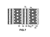
- FIG. 7 A sectional view of stacked fuel cells using a series of bipolar plates in accordance with the present invention.
- FIG. 8 SMC bipolar plate conductivity as a function of top layer-to-resin mixture layer thickness ratio for the first set of examples.
- a prior art fuel cell typically comprises a membrane electrode assembly 8 , which comprises a proton exchange membrane 14 (PEM), an anode backing layer 10 connected to one face of the PEM 14 , and a cathode backing layer 12 connected to the opposite face of PEM 14 .
- Anode backing layer 10 is also referred to as a fluid diffusion layer or diffuser, typically made of carbon paper or carbon cloth.
- a platinum/ruthenium electro-catalytic film 16 is positioned at the interface between the anode backing layer and PEM 14 for promoting oxidation of the methanol fuel.
- a backing layer or diffuser 12 e.g., carbon paper or carbon cloth
- a platinum electro-catalytic film 18 positioned at the interface between the cathode backing layer and PEM 14 for promoting reduction of the oxidant.
- the proton exchange membrane in a PEM-based fuel cell is typically coated on both sides with a catalyst (e.g., Pt/Ru or Pt) to form a catalyst-coated membrane 9 (CCM).
- CCM catalyst-coated membrane 9
- the CCM layer 9 is then sandwiched between an anode backing layer 10 (diffuser) and a cathode backing layer 12 (diffuser).
- the resulting five-layer assembly is called a membrane electrode assembly 8 (MEA).
- MEA membrane electrode assembly 8
- some fuel cell workers sometimes refer to CCM as a MEA, we prefer to take the MEA to mean a five-layer configuration: anode backing layer, anode catalyst layer, PEM, cathode catalyst layer, and cathode backing layer.
- the fuel cell also comprises a pair of fluid distribution plates (also referred to as fluid flow field plates) 21 and 23 , which are positioned on opposite sides of membrane electrode assembly 8 .
- Plate 21 which serves as a fuel distribution plate, is shaped to define fuel flow channels 22 facing towards anode diffuser 10 .
- Channels 22 are designed to uniformly deliver the fuel to the diffuser, which transports the fuel to the anode catalyst layer 16 .
- An input port and an output port (not shown), being in fluid communication with channels 22 , may also be provided in flow field plate 21 so that carbon dioxide (in a DMFC) can be withdrawn from channels 22 .
- Flow field plate 23 is shaped to include fluid channels 24 for passage of a quantity of gaseous oxygen (or air).
- An input port and an output port are provided in plate 23 , which are in fluid communication with channels 24 so that oxygen (or air) can be transported through the input port to the cathode diffuser 12 and cathode catalyst layer 18 , and water and excess oxygen (or air) can be withdrawn from channels 24 through the output port.
- Plate 23 is electrically conductive and in electrical contact with cathode diffuser 12 . It can be used as a uni-polar plate (the positive terminal of the electrical current generated by the fuel cell unit) or as a part of a bi-polar plate (if integrated with fuel flow field plate 21 ). Shown in FIG.
- FIG. 2 is a fuel cell stack that consists of two fuel cell units. On the two opposite sides of the stack are two separate flow field plates 21 a , 23 a . Between the two MEAs ( 8 a and 8 b ) is a bipolar plate 19 , which can be viewed as two flow field plates integrated into one single component.
- SMCs sheet molding compounds
- the resin and chopped fibers are sandwiched between films of plastic material to form a laminated structure which is wound in coiled form.
- the laminate is stored under conditions which will not result in final curing of the resin.
- the laminate is uncoiled and cut to the desired size and shape for the molding operation.
- specific procedures must be employed to provide a thorough impregnation of fibers with the resin. Impregnation can be achieved by passing the laminated structure between cooperating rolls or flexing the laminate in concave and convex shapes.
- the present invention provides a method of producing a highly conductive SMC composition and a fuel cell flow field plate or bipolar plate made from this SMC composition.
- the SMC composition prior to shaping and curing into a flow field or bipolar plate, is a laminated structure comprising a top sheet, a bottom sheet and a core layer sandwiched between these two sheets.
- the SMC-based bipolar plate schematically shown in FIG. 3( a ), comprises a top sheet 71 , a bottom sheet 73 , and a resin mixture 75 sandwiched between the top sheet and the bottom sheet. At least one of the top sheet and the bottom sheet comprises a flexible graphite sheet.
- the flexible graphite sheet (e.g., the top sheet 71 ) has a planar outer surface 77 having formed therein a fluid flow channel 79 .
- the resin mixture 75 comprises a thermoset resin (with or without a catalyst) and a conductive filler present in a sufficient quantity to render the SMC composition electrically conductive enough to be a current collector material (with a conductivity of the SMC preferably no less than 100 S/cm).
- a current collector material with a conductivity of the SMC preferably no less than 100 S/cm
- the thermoset resin can be any resin which, upon exposure to heat or high energy radiation (e.g., electron beam), becomes cured (e.g., forming a cross-linked polymer chain network).
- the thermoset resin may be advantageously selected from the group consisting of unsaturated polyester resins, vinyl esters, epoxies, phenolic resins, polyimide resins, bismaleimide resins, polyurethane resins, and combinations thereof.
- the method for producing a SMC composition for use as a fuel cell flow field plate or bipolar plate material comprises: (a) providing a continuous sheet of a substrate material (becoming the bottom sheet), preferably from a roller or drum; (b) feeding a resin mixture to a surface of the substrate material sheet with the resin mixture comprising a thermoset resin and a conductive filler; (c) providing a continuous sheet of flexible graphite (becoming the top sheet) onto the resin mixture in such way that the resin mixture forms a core layer sandwiched between the substrate material sheet and the flexible graphite sheet to obtain a laminated structure; and (d) compressing the laminated structure (for facilitating filler-resin mixing) to obtain the SMC composition which is collected on a winding device, such as a motorized roller. This is a roll-to-roll process that is amenable to mass production of SMC.
- each flexible graphite sheet has a substantially planar outer surface (e.g., surface 77 on the top sheet 71 and surface 81 on the bottom sheet 73 ) having fluid flow channels (e.g., channel 79 on the top sheet and 83 on the bottom sheet) molded therein.
- fluid flow channels are preferably created through embossing during or after the SMC plate is made on a continuous basis.
- the conductive filler in the resin mixture may be selected from small-sized particles (preferably smaller than 10 ⁇ m and more preferably smaller than 1 ⁇ m) such as a carbon black, graphite particle, nano-scaled graphene plate, graphitic nano-fiber, metal particle, or a combination thereof.
- small-sized particles preferably smaller than 10 ⁇ m and more preferably smaller than 1 ⁇ m
- carbon or graphite fibers fiber diameter typically greater than 12 ⁇ m
- a second thermoset resin or a thermoplastic may be used to adjust the mixture viscosity and to assist in bonding the filler particles together.
- a quantity of other types of reinforcement fiber such as glass fiber or polymer fiber, may be added to impart additional structural integrity to the resin mixture layer and that of the SMC.
- the type and proportion of the conductive filler are preferably chosen in such a way that the bulk conductivity of the resulting resin mixture is greater than 10 S/cm, further preferably greater than 50 S/cm, and most preferably greater than 100 S/cm.
- the conductive filler proportion in the resin mixture is between 3% and 20% by weight (based on the total weight of the resin mixture)
- the bulk conductivity of the resin mixture exceeds 10 S/cm, up to approximately 35 S/cm, depending on the filler type.
- the proportion is between approximately 20% and 45%, the resin matrix conductivity exceeds 50 S/cm.
- the proportion is greater than 45%, the resin matrix conductivity exceeds 100 S/cm.
- SMC plates having an overall conductivity mostly greater than 100 S/cm, typically greater than 200 S/cm, and, in many cases, even greater 250 S/cm, far exceeding the US Department of Energy conductivity target (100 S/cm) for composite bipolar plates.
- the flexible graphite sheet and the plastic sheet may be laminated initially into a three-layer SMC structure ( FIG. 3( b )).
- a mold release agent may be used between the plastic sheet and the resin mixture layer to facilitate later separation of the plastic sheet from the resin mixture-bonded flexible graphite plate. Embossing or matched-mold pressing is carried out before, during, and/or after resin curing to produce flow channels 79 a on the outer surface 77 a of the flexible graphite sheet 71 a .
- the plastic sheet or film 73 a is then peeled off, leaving behind a two-layer plate ( FIG. 3( c )) that can be used as a flow field plate.
- the top sheet is a flexible graphite foil
- the bottom sheet can be an electrically conductive film or foil, such as a carbon paper, carbon or graphite fabric, conductive polymer film, or metal foil. This will also make a good bipolar plate.
- both the top and bottom sheets can be selected from a carbon paper, carbon/graphite fabric, carbon/graphite fiber-containing mat, conductive polymer film, thin metal foil and/or flexible graphite. In theses cases, a portion of the thermoset resin in the resin mixture of the core layer can permeate into the top or bottom layer to further enhance the structural integrity of the resulting laminate.
- the overall conductivity of a two-layer flow field plate or a three-layer bipolar plate also depends upon the relative thickness of the resin matrix layer (or core layer) with respect to the total thickness of the flexible graphite sheets. Since the flexible graphite is highly conductive (typically with a conductivity greater than 300 S/cm) and the resin matrix layer is typically lower than flexible graphite in conductivity, the resin matrix layer should be made as thin as possible to achieve a maximum electronic conductivity. When the resin matrix conductivity is relatively low (e.g., 10 S/cm), a ratio of core layer thickness-to-total flexible graphite thickness typically is as small as 1/15 in order to achieve a bipolar plate conductivity of 100 S/cm or greater.
- the resin mixture layer is thinner than 40 ⁇ m.
- the resin mixture layer has to be lower than 10 ⁇ m.
- a certain minimum core layer thickness may be desired to obtain a desired level of mechanical stiffness or strength of the bipolar plate.
- the resin matrix conductivity is higher (e.g., 50 S/cm)
- a much higher ratio of core layer thickness-to-total flexible graphite thickness can be used in order to achieve a bipolar plate conductivity of 100 S/cm.
- the resin mixture layer can be almost as thick as a flexible graphite sheet. More advantageously, when each flexible graphite sheet is approximately 300 ⁇ m thick and when the resin mixture layer is 60 ⁇ m or thinner, a bipolar plate conductivity as high as 200 S/cm can be achieved.
- a resin matrix layer of approximately 60 ⁇ m can be prepared quite easily.
- another embodiment of the present invention is a sheet molding compound composition, comprising a top sheet, a bottom sheet, and a resin mixture sandwiched between the top sheet and the bottom sheet.
- the top sheet and/or the bottom sheet comprises a flexible graphite sheet.
- the resin mixture comprises a thermoset resin and a conductive filler present in a sufficient quantity to render the resin mixture electrically conductive with a bulk conductivity of the resin mixture no less than 10 S/cm (preferably no less than 50 S/cm).
- the resulting three-layer SMC composition upon completion of resin curing to make a SMC product, has a conductivity mostly above 100 S/cm, typically above 200 S/cm, and, in several cases, above 250 S/cm.
- the conducting filler material may be selected from carbon fibers, metal fibers, metal particles (preferably nano-scaled), carbon nano-tubes (CNTs), graphitic nano-fibers (GNFs), nano-scaled graphene plates, carbon blacks, or a combination thereof.
- Individual nano-scaled graphite planes (individual graphene sheets) and stacks of multiple nano-scaled graphene sheets are collectively called nano-sized graphene plates (NGPs).
- NGPs nano-sized graphene plates
- the structures of these materials may be best visualized by making a longitudinal scission on the single-wall or multi-wall of a nano-tube along its tube axis direction and then flattening up the resulting sheet or plate.
- nano materials have strength, stiffness, and electrical conductivity that are comparable to those of carbon nano-tubes, but NGPs can be mass-produced at lower costs. They can be produced by reducing the expanded graphite particles to much smaller sizes (100 nanometers or smaller).
- the preparation of other nano-scaled carbon-based materials, including CNTs, GNFs, and carbon black, is well-known in the art. They are all commercially available, along with nano-scaled metal particles.
- These nano-scaled, electrically conductive filler materials are preferred conductive filler ingredients for use in making the presently invented SMCs. It may be further noted that CNTs, GNFs, and NGPs are known to be capable of imparting high strength and stiffness to a resin matrix. They are ideally suited for the present applications.
- the preparation of a flexible graphite SMC composition may begin with continuously or intermittently feeding (uncoiling) a thin flexible graphite sheet 34 (a bottom sheet in the present context) from a winding drum 32 .
- the surface of the flexible graphite sheet 34 may be coated (or pre-coated) with a desired layer 36 of an uncured thermoset resin via a number of prior art coating techniques (e.g., spraying, printing, spin-coating, or, simply, brushing).
- a powder dispenser 38 is then operated to deposit a desired amount of a conductive filler 40 (or conductive filler plus some resin) onto the top surface of the thermoset resin layer 36 while the flexible graphite sheet is being driven forward to the right.
- the conductive filler is typically a mixture of conductive particles and fibers (non-conductive or, preferably, conductive).
- a leveling device 42 e.g., a scraping blade
- a top sheet also coated or pre-coated with a thermoset resin layer 48 (with same or different composition)
- a thermoset resin layer 48 with same or different composition
- This laminated pre-SMC composition is then fed through the gap between a pair of rollers 47 a , 47 b to compress the composition 50 a .
- a series of rollers are used to assist in mixing of the resin with the conductive filler.
- impregnation or mixing of the filler particles/fibers with the resin can be achieved by passing the laminated structure 50 a between cooperating rolls or flexing the laminate in concave and convex shapes to obtain a well-mixed SMC 50 b , which can be wound up on a roller 51 .
- the SMC may be stored under conditions which will not result in final curing of the resin.
- a catalyst inhibitor may be used to extend the shelf or storage life of the SMC without premature curing.
- the SMC When a flow field plate or bipolar plate is needed, the SMC is uncoiled and cut to the desired size and shape for the molding operation. Compression molding, hot pressing, or matched-die molding may be used to create flow channels on the outer surfaces of the plate while the thermoset resin is being cured and hardened.
- a continuous sheet of SMC is fabricated in a procedure similar to that in FIG. 4( a ).
- Heating means may be used to advance the cure reaction of the thermoset resin (e.g., in a heating zone indicated by a phantom box of FIG. 4( b )) to achieve a desired degree of curing before the SMC is embossed or match-molded between a pair of embossing tools 11 a , 11 b or matting mold platens to create the desired flow field channels. These tools or mold platens may also be heated.
- the laminated sheet ( 50 a or 50 b ) continues to move forward, another portion of the sheet is embossed or molded. This is a continuous process that is suitable for cost-effective mass production of flow field plates or bipolar plates that are highly conductive.
- one of the flexible sheets is a plastic film
- this film may be peeled off after resin is cured to obtain a flow field plate (e.g., FIG. 3( c ).
- coolant channels can be created during the SMC molding process in several ways. For instance, during the flow field plate molding process, the mold surface may be shaped to produce a part of a channel groove (e.g., 52 a in FIG. 5( a )). Two matting flow field plates may then be positioned together to form a bipolar plate 54 ( FIG. 5( b )) having complete coolant channels (e.g., 52 ).
- the ingredients may be artificially divided into two categories: (a) nano-scale fillers (e.g., CNTs, GNFs and NGPs for both structural reinforcement and conductivity enhancement of the thermoset resin, and nano-scale metal particles, carbon black powder, and nano-scaled graphite particles mainly for conductivity enhancement) and (b) micron-diameter or larger fillers (chopped glass fibers for structural reinforcement, micron or larger graphite particles for conductivity enhancement, and short carbon/graphite fibers for both structural reinforcement and conductivity enhancement).
- nano-scale fillers e.g., CNTs, GNFs and NGPs for both structural reinforcement and conductivity enhancement of the thermoset resin, and nano-scale metal particles, carbon black powder, and nano-scaled graphite particles mainly for conductivity enhancement
- micron-diameter or larger fillers chopped glass fibers for structural reinforcement, micron or larger graphite particles for conductivity enhancement, and short carbon/graphite fibers for both structural reinforcement and conductivity enhancement.
- micron-diameter fibers for being incorporated into the conductive filler-resin mixture: a multi-end roving (strands of continuous fibers), and pre-cut short fibers (typically micron to mm in length).
- thermoset resin and the filler may be supplied in three separate components and then combined and mixed.
- the SMC process consists of chopping fibers 40 a onto a sheet of substrate material 34 (flexible graphite, carbon paper, thin metal foil, carbon fiber mat, or plastic film like polyethylene, etc.) on which a resin-filler paste 43 b has been doctored.
- a predetermined amount of this mixture paste 43 a placed on top of another film 46 a (flexible graphite), is then conveyed forward to receive the dropping chopped fibers.
- the “sandwich” of resin mixture and chopped fibers is passed between compaction rolls 47 a , 47 b to wet the fibers and thoroughly mix the ingredients.
- the mixture is then cured slightly (called aging, maturing, or B-staging) to produce a SMC composition 50 b with the resin mixture having a leather-like texture and rolled-up for storage or shipment.
- the bottom sheet may come from the source roller 32 b over a guiding roller 32 a and, similarly, the top sheet may come from a source roller 44 b over a guiding roller 44 a.
- a SMC-based flow field plate or bipolar plate can be produced directly in line, as schematically shown in FIG. 4( d ).
- a continuous sheet of SMC is fabricated in a procedure similar to that in FIG. 4( c ).
- Heating means may be used to advance the cure reaction of the thermoset resin (e.g., in a heating zone indicated by a phantom box of FIG. 4( d )) to achieve a desired degree of curing before the SMC is embossed or matched-die molded between a pair of embossing tools 11 a , 11 b or matting mold platens to create the desired flow field channels. These tools or mold platens may also be heated.
- the laminated sheet ( 50 a or 50 b ) continues to move forward, another portion of the sheet is embossed or molded. This is a continuous process that is suitable for cost-effective mass production of flow field plates or bipolar plates that are highly conductive.
- coolant channels are built into a bipolar plate when it is molded.
- two uncured or partially cured bi-layer SMC plates (with the plastic film peeled off, leaving behind a resin mixture layer 63 a or 63 b and flexible graphite layer 65 a or 65 b ) may be molded between a pair of matched molds ( 61 a , 61 b ) and a number of molding pins 67 .
- These pins, coated with a mold release agent, may be pulled out of the SMC structure to obtain an integral bipolar plate 54 ( FIG. 6( b )) with built-in coolant channels 67 a .
- coolant channels may be fitted with connectors, preferably before the resin matrix material is solidified.
- FIG. 7 shows back-to-back flow field plates that are fabricated as one monolithic component 54 , with coolant channels 52 formed as complete channels within the component, as well as reactant channels 60 & 62 .
- the two outer surfaces of bipolar plate 54 are stacked against respective diffuser layers 56 , 58 (preferably made of carbon paper), which are in turn connected to catalyst-coated membrane (e.g., 70 ).
- the present invention also provides a fuel cell or a stack of fuel cells that comprises a highly conductive flow field plate or bipolar plate component as defined in any of the aforementioned preferred embodiments.
- the resulting fuel cell system is of lower costs (due to their amenability to mass production) and better performance (due to lower contact resistance and internal resistance and, hence, higher voltage).
- FIG. 8 further illustrates how the overall conductivity of a three-layer bipolar plate depends upon the ratio of the resin mixture layer (or core layer) thickness to the thickness of a flexible graphite sheet (for Samples 1-9, the set of examples that have the highest resin mixture resistivity).
- a top layer/core layer thickness ratio of approximately 7.5 or higher gives the 3-layer plate a conductivity greater than 100 S/cm.
- the resin mixture layer is 40 ⁇ m or thinner.
- the resin mixture layer has to be lower than 10 ⁇ m (further preferably ⁇ 5 ⁇ m).
- any top layer/core layer ratio from 1/1 to 130/1 is good enough to result in a high bipolar plate conductivity (greater than 100 S/cm). Any ratio greater than 5/1 leads to a plate conductivity greater than 200 S/cm.
Landscapes
- Engineering & Computer Science (AREA)
- Mechanical Engineering (AREA)
- Chemical & Material Sciences (AREA)
- Composite Materials (AREA)
- Fuel Cell (AREA)
Abstract
Description
(3) Mixing most (if not all) of the nano-scale filler ingredients (including necessary catalyst, inhibitor, and viscosity adjusters, etc.) to form a resin mixture paste, which is then delivered by the bottom sheet and the top sheet to mix with other remaining ingredients (e.g., chopped fibers) of the conductive filler to form a core layer between the top sheet and bottom sheet, as illustrated in
| TABLE 1 |
| Properties of SMC bipolar plates (flexible graphite resistivity = 0.00333 Ω-cm). |
| Core layer resin mixture | Top layer | Core layer | Core | Plate | |
| Sample | composition | thickness | resistivity | thickness | conductivity |
| No. | (Weight %) | I1 (cm) | ρ2 (Ω-cm) | I2 (μm) | σ (S/cm) |
| 1 | 65% Ep, 35% Ag | 0.03 | 0.10 | 1.3 | 282 |
| 2 | 65% Ep, 25% Ag, 10% NGP | 0.03 | 0.11 | 3.2 | 260 |
| 3 | 65% Ep, 25% Ag, 10% GNF | 0.03 | 0.12 | 12 | 191 |
| 4 | 65% Ep, 34% Ag, 1% CNT | 0.03 | 0.11 | 31 | 124 |
| 5 | 65% Ep, 20% CB, 15% NGP | 0.03 | 0.13 | 55 | 87 |
| 6 | 65% Ep, 35% GP | 0.03 | 0.11 | 78 | 69 |
| 7 | 65% Ep, 25% GP, 10% CF | 0.03 | 0.12 | 120 | 51 |
| 8 | 65% Ep, 30% GP, 5% GL | 0.03 | 0.14 | 220 | 34 |
| 9 | 65% Ep, 25% GP, 10% CF | 0.03 | 0.12 | 310 | 27 |
| 10 | 35% Ep, 35% Ag, 30% NGP | 0.03 | 0.010 | 3.7 | 297 |
| 11 | 35% Ep, 55% Ag, 10% NGP | 0.03 | 0.011 | 5.6 | 294 |
| 12 | 35% Ep, 55% Ag, 10% GNF | 0.03 | 0.012 | 15 | 286 |
| 13 | 35% Ep, 50% Ag, 15% CNT | 0.03 | 0.011 | 33 | 272 |
| 14 | 35% Ep, 40% CB, 25% NGP | 0.03 | 0.013 | 45 | 263 |
| 15 | 35% Ep, 65% GP | 0.03 | 0.011 | 75 | 245 |
| 16 | 35% Ep, 55% GP, 10% CF | 0.03 | 0.012 | 160 | 211 |
| 17 | 35% Ep, 60% GP, 5% GL | 0.03 | 0.014 | 220 | 195 |
| 18 | 35% Ep, 55% GP, 10% CF | 0.03 | 0.012 | 310 | 178 |
| 19 | 50% VE, 50% Ag | 0.03 | 0.021 | 2.3 | 294 |
| 20 | 50% VE, 40% Ag, 10% NGP | 0.03 | 0.023 | 4.6 | 289 |
| 21 | 50% VE, 40% Ag, 10% GNF | 0.03 | 0.024 | 11 | 275 |
| 22 | 50% VE, 44% Ag, 1% CNT | 0.03 | 0.023 | 29 | 243 |
| 23 | 50% VE, 30% CB, 20% NGP | 0.03 | 0.026 | 45 | 222 |
| 24 | 50% VE, 50% GP | 0.03 | 0.023 | 63 | 203 |
| 25 | 50% VE, 40% GP, 10% CF | 0.03 | 0.024 | 88 | 183 |
| 26 | 50% VE, 45% GP, 5% GL | 0.03 | 0.027 | 176 | 140 |
| 27 | 50% VE, 40% GP, 10% CF | 0.03 | 0.024 | 260 | 119 |
| 28 | 50% VE, 40% GP, 10% CF | 0.03 | 0.024 | 320 | 109 |
| Note: | |||||
| Ep = epoxy, | |||||
| VE = vinyl ester resin, | |||||
| GP = fine graphite particles, | |||||
| NGP = nano graphene plate, | |||||
| CB = carbon black, | |||||
| CF = carbon fiber, | |||||
| GL = glass fiber, | |||||
| GNF = graphitic nano-fiber, | |||||
| Ag = silver nano particles, | |||||
| CNT = carbon nano-tubes. | |||||
Claims (28)
Priority Applications (1)
| Application Number | Priority Date | Filing Date | Title |
|---|---|---|---|
| US11/293,541 US8597453B2 (en) | 2005-12-05 | 2005-12-05 | Method for producing highly conductive sheet molding compound, fuel cell flow field plate, and bipolar plate |
Applications Claiming Priority (1)
| Application Number | Priority Date | Filing Date | Title |
|---|---|---|---|
| US11/293,541 US8597453B2 (en) | 2005-12-05 | 2005-12-05 | Method for producing highly conductive sheet molding compound, fuel cell flow field plate, and bipolar plate |
Publications (2)
| Publication Number | Publication Date |
|---|---|
| US20070125493A1 US20070125493A1 (en) | 2007-06-07 |
| US8597453B2 true US8597453B2 (en) | 2013-12-03 |
Family
ID=38117555
Family Applications (1)
| Application Number | Title | Priority Date | Filing Date |
|---|---|---|---|
| US11/293,541 Expired - Fee Related US8597453B2 (en) | 2005-12-05 | 2005-12-05 | Method for producing highly conductive sheet molding compound, fuel cell flow field plate, and bipolar plate |
Country Status (1)
| Country | Link |
|---|---|
| US (1) | US8597453B2 (en) |
Cited By (5)
| Publication number | Priority date | Publication date | Assignee | Title |
|---|---|---|---|---|
| CN105261423A (en) * | 2015-10-30 | 2016-01-20 | 中山大学 | Roll-to-roll preparation device and method for high-performance flexible transparent conductive film |
| WO2022140691A1 (en) | 2020-12-23 | 2022-06-30 | Magna Exteriors Inc. | Graphene enhanced sheet molding compound |
| WO2023060347A1 (en) * | 2021-10-13 | 2023-04-20 | Nanoxplore Inc. | Sheet molding compound reinforced with graphene flakes, and methods of producing the same |
| US11655353B2 (en) | 2017-08-03 | 2023-05-23 | Teijin Automotive Technologies, Inc. | Graphene nanoplatelet modified sheet molding compositions |
| US11912007B2 (en) | 2020-12-21 | 2024-02-27 | Horton World Solutions, Llc | Composite structured laminate and method of manufacture |
Families Citing this family (40)
| Publication number | Priority date | Publication date | Assignee | Title |
|---|---|---|---|---|
| US8518603B2 (en) * | 2005-12-05 | 2013-08-27 | Nanotek Instruments, Inc. | Sheet molding compound flow field plate, bipolar plate and fuel cell |
| US8501307B2 (en) * | 2007-09-04 | 2013-08-06 | Nanotek Instruments, Inc. | Recompressed exfoliated graphite articles |
| KR101090704B1 (en) * | 2008-04-25 | 2011-12-08 | 한국과학기술원 | Separation plate for Polymer Electrolyte Membrane Fuel Cell and method for manufacturing the same |
| US8758957B2 (en) * | 2008-07-29 | 2014-06-24 | GM Global Technology Operations LLC | Graphene coated SS bipolar plates |
| US20100092809A1 (en) * | 2008-10-10 | 2010-04-15 | Board Of Trustees Of Michigan State University | Electrically conductive, optically transparent films of exfoliated graphite nanoparticles and methods of making the same |
| WO2010115173A1 (en) * | 2009-04-03 | 2010-10-07 | Vorbeck Materials Corp | Polymer compositions containing graphene sheets and graphite |
| ES2717903T3 (en) * | 2009-10-16 | 2019-06-26 | Graphene Square Inc | Graphene roll-to-roll transfer procedure, graphene roll produced by the procedure, and roll-to-roll transfer equipment for graphene |
| DE102009051434A1 (en) | 2009-10-30 | 2011-05-05 | Zentrum für Brennstoffzellen-Technik GmbH | Molded body made of highly conductive molding mass that contains a plastic and a filler incorporated into the plastic, useful as sealing including ring, bracelet and rubber gasket, as bipolar plate for an electrochemical cell, and as pipe |
| TWI375347B (en) * | 2009-11-20 | 2012-10-21 | Ind Tech Res Inst | Manufacture method of bi-polar plates of fuel cell and bi-polar plates thereof |
| DE102009054427B4 (en) * | 2009-11-25 | 2014-02-13 | Kme Germany Ag & Co. Kg | Method for applying mixtures of carbon and metal particles to a substrate, substrate obtainable by the method and its use |
| KR101134482B1 (en) | 2009-11-30 | 2012-04-13 | 한국과학기술원 | Separation plate for Polymer Electrolyte Membrane Fuel Cell and method for manufacturing the same |
| KR101234180B1 (en) * | 2009-12-30 | 2013-02-18 | 그래핀스퀘어 주식회사 | Roll-to-roll doping method of graphene film and doped graphene film |
| US8914176B2 (en) * | 2012-01-23 | 2014-12-16 | Nanotek Instruments, Inc. | Surface-mediated cell-powered vehicles and methods of operating same |
| US9716299B2 (en) * | 2012-10-25 | 2017-07-25 | The Regents Of The University Of California | Graphene based thermal interface materials and methods of manufacturing the same |
| US20140378026A1 (en) * | 2013-06-19 | 2014-12-25 | Hasbro, Inc. | Apparatus and method for shaping and extruding formable material |
| US9150998B2 (en) * | 2013-08-29 | 2015-10-06 | J. Michael Dywan | Method and apparatus for producing detailed fabric applique |
| FR3023746B1 (en) * | 2014-07-21 | 2016-07-29 | Univ Paul Sabatier - Toulouse Iii | PROCESS FOR PREPARING AN ELECTRICALLY CONDUCTIVE LAMINATED COMPOSITE STRUCTURE |
| HK1249156A1 (en) * | 2015-03-27 | 2018-10-26 | Golconda Holdings Llc | System, method, and apparatus for magnetic surface coverings |
| US10418647B2 (en) | 2015-04-15 | 2019-09-17 | Lockheed Martin Energy, Llc | Mitigation of parasitic reactions within flow batteries |
| US10804540B2 (en) | 2015-05-01 | 2020-10-13 | Pivotal Battery Corp | Bipolar plate and method of making and using same |
| US10005099B2 (en) * | 2015-07-20 | 2018-06-26 | Nanotek Instruments, Inc. | Production of highly oriented graphene oxide films and graphitic films derived therefrom |
| US11005113B2 (en) | 2015-08-19 | 2021-05-11 | Lockheed Martin Energy, Llc | Solids mitigation within flow batteries |
| CN106876756B (en) * | 2015-12-10 | 2023-06-23 | 上海神力科技有限公司 | A method for continuous production of single cells for fuel cells |
| CN106876724A (en) * | 2015-12-10 | 2017-06-20 | 上海神力科技有限公司 | A kind of fuel cell rolling production method of soft graphite unipolar plate |
| CN106876723B (en) * | 2015-12-10 | 2023-06-23 | 上海神力科技有限公司 | A method for continuous production of flexible graphite plate single cells for fuel cells |
| CN105803522B (en) * | 2016-03-30 | 2018-02-13 | 北京大学 | A kind of continuous method for preparing large single crystal graphene |
| US10381674B2 (en) | 2016-04-07 | 2019-08-13 | Lockheed Martin Energy, Llc | High-throughput manufacturing processes for making electrochemical unit cells and electrochemical unit cells produced using the same |
| US10147957B2 (en) * | 2016-04-07 | 2018-12-04 | Lockheed Martin Energy, Llc | Electrochemical cells having designed flow fields and methods for producing the same |
| US10093041B2 (en) | 2016-04-11 | 2018-10-09 | The Boeing Company | Conductive pre-impregnated composite sheet and method for making the same |
| US10109879B2 (en) | 2016-05-27 | 2018-10-23 | Lockheed Martin Energy, Llc | Flow batteries having an electrode with a density gradient and methods for production and use thereof |
| US10332693B2 (en) | 2016-07-15 | 2019-06-25 | Nanotek Instruments, Inc. | Humic acid-based supercapacitors |
| JP7042800B2 (en) * | 2016-08-18 | 2022-03-28 | ナノテク インストゥルメンツ,インコーポレイテッド | Highly oriented humic acid film and the highly conductive graphite film obtained from it, and devices containing the film. |
| US10403911B2 (en) | 2016-10-07 | 2019-09-03 | Lockheed Martin Energy, Llc | Flow batteries having an interfacially bonded bipolar plate-electrode assembly and methods for production and use thereof |
| US10573899B2 (en) | 2016-10-18 | 2020-02-25 | Lockheed Martin Energy, Llc | Flow batteries having an electrode with differing hydrophilicity on opposing faces and methods for production and use thereof |
| US10581104B2 (en) | 2017-03-24 | 2020-03-03 | Lockheed Martin Energy, Llc | Flow batteries having a pressure-balanced electrochemical cell stack and associated methods |
| CN112038653A (en) * | 2020-08-13 | 2020-12-04 | 重庆市海龙模具有限公司 | Enhanced bipolar plate structure and manufacturing method |
| CN112103516B (en) * | 2020-09-17 | 2024-07-09 | 国鸿氢能科技(嘉兴)股份有限公司 | Continuous roll forming device and method for manufacturing graphite bipolar plate |
| CN113839061A (en) * | 2021-11-30 | 2021-12-24 | 北京理工大学深圳汽车研究院(电动车辆国家工程实验室深圳研究院) | Composite material for preparing fuel cell bipolar plate and application thereof |
| CN114976090A (en) * | 2022-06-02 | 2022-08-30 | 开封时代新能源科技有限公司 | Method for manufacturing integrated bipolar reaction plate |
| CN115275250B (en) * | 2022-06-15 | 2025-09-30 | 湖北魔方新能源科技有限公司 | A roll forming device for flexible graphite plates of fuel cells |
Citations (14)
| Publication number | Priority date | Publication date | Assignee | Title |
|---|---|---|---|---|
| US5300370A (en) | 1992-11-13 | 1994-04-05 | Ballard Power Systems Inc. | Laminated fluid flow field assembly for electrochemical fuel cells |
| US5527363A (en) | 1993-12-10 | 1996-06-18 | Ballard Power Systems Inc. | Method of fabricating an embossed fluid flow field plate |
| US5885728A (en) | 1997-04-04 | 1999-03-23 | Ucar Carbon Technology Corporation | Flexible graphite composite |
| US6037073A (en) | 1996-10-15 | 2000-03-14 | Lockheed Martin Energy Research Corporation | Bipolar plate/diffuser for a proton exchange membrane fuel cell |
| US6248467B1 (en) | 1998-10-23 | 2001-06-19 | The Regents Of The University Of California | Composite bipolar plate for electrochemical cells |
| US20020132152A1 (en) * | 1999-02-09 | 2002-09-19 | Kazuo Saito | Separator for fuel cell and solid polymer type fuel cell using said separator |
| US6508906B1 (en) * | 2000-03-15 | 2003-01-21 | Patent Holding Company | Carbon fiber-filled sheet molding compound and method of manufacturing same |
| US20030143452A1 (en) * | 2002-01-30 | 2003-07-31 | Aisin Seiki Kabushiki Kaisha | Conductive member, a method for manufacturing the same and a method for manufacturing a separator for use in a fuel cell |
| US20040229993A1 (en) | 2003-02-19 | 2004-11-18 | Jianhua Huang | Highly conductive thermoplastic composites for rapid production of fuel cell bipolar plates |
| US20050031933A1 (en) * | 2003-08-06 | 2005-02-10 | Blunk Richard H. | Adhesive bonds for metalic bipolar plates |
| US6881512B2 (en) | 1998-12-17 | 2005-04-19 | Nisshinbo Industries, Inc. | Separator for fuel cell, process for production thereof, and solid polymer type fuel cell using said separator |
| US6939638B2 (en) | 2000-07-06 | 2005-09-06 | Nisshinbo Industries, Inc. | Fuel cell separator, process for production thereof, and polymer electrolyte fuel cell |
| US20070065703A1 (en) * | 2005-09-19 | 2007-03-22 | Abd Elhamid Mahmoud H | Durable conductive adhesive bonds for fuel cell separator plates |
| US7338573B2 (en) * | 2000-11-26 | 2008-03-04 | Magnetnotes, Ltd. | Magnetic substrates with high magnetic loading |
-
2005
- 2005-12-05 US US11/293,541 patent/US8597453B2/en not_active Expired - Fee Related
Patent Citations (15)
| Publication number | Priority date | Publication date | Assignee | Title |
|---|---|---|---|---|
| US5300370A (en) | 1992-11-13 | 1994-04-05 | Ballard Power Systems Inc. | Laminated fluid flow field assembly for electrochemical fuel cells |
| US5527363A (en) | 1993-12-10 | 1996-06-18 | Ballard Power Systems Inc. | Method of fabricating an embossed fluid flow field plate |
| US6037073A (en) | 1996-10-15 | 2000-03-14 | Lockheed Martin Energy Research Corporation | Bipolar plate/diffuser for a proton exchange membrane fuel cell |
| US6171720B1 (en) | 1996-10-15 | 2001-01-09 | Ut-Battelle, Llc | Bipolar plate/diffuser for a proton exchange membrane fuel cell |
| US5885728A (en) | 1997-04-04 | 1999-03-23 | Ucar Carbon Technology Corporation | Flexible graphite composite |
| US6248467B1 (en) | 1998-10-23 | 2001-06-19 | The Regents Of The University Of California | Composite bipolar plate for electrochemical cells |
| US6881512B2 (en) | 1998-12-17 | 2005-04-19 | Nisshinbo Industries, Inc. | Separator for fuel cell, process for production thereof, and solid polymer type fuel cell using said separator |
| US20020132152A1 (en) * | 1999-02-09 | 2002-09-19 | Kazuo Saito | Separator for fuel cell and solid polymer type fuel cell using said separator |
| US6508906B1 (en) * | 2000-03-15 | 2003-01-21 | Patent Holding Company | Carbon fiber-filled sheet molding compound and method of manufacturing same |
| US6939638B2 (en) | 2000-07-06 | 2005-09-06 | Nisshinbo Industries, Inc. | Fuel cell separator, process for production thereof, and polymer electrolyte fuel cell |
| US7338573B2 (en) * | 2000-11-26 | 2008-03-04 | Magnetnotes, Ltd. | Magnetic substrates with high magnetic loading |
| US20030143452A1 (en) * | 2002-01-30 | 2003-07-31 | Aisin Seiki Kabushiki Kaisha | Conductive member, a method for manufacturing the same and a method for manufacturing a separator for use in a fuel cell |
| US20040229993A1 (en) | 2003-02-19 | 2004-11-18 | Jianhua Huang | Highly conductive thermoplastic composites for rapid production of fuel cell bipolar plates |
| US20050031933A1 (en) * | 2003-08-06 | 2005-02-10 | Blunk Richard H. | Adhesive bonds for metalic bipolar plates |
| US20070065703A1 (en) * | 2005-09-19 | 2007-03-22 | Abd Elhamid Mahmoud H | Durable conductive adhesive bonds for fuel cell separator plates |
Cited By (6)
| Publication number | Priority date | Publication date | Assignee | Title |
|---|---|---|---|---|
| CN105261423A (en) * | 2015-10-30 | 2016-01-20 | 中山大学 | Roll-to-roll preparation device and method for high-performance flexible transparent conductive film |
| CN105261423B (en) * | 2015-10-30 | 2017-08-29 | 中山大学 | A kind of volume to volume prepares the equipment and method of high-performance flexible nesa coating |
| US11655353B2 (en) | 2017-08-03 | 2023-05-23 | Teijin Automotive Technologies, Inc. | Graphene nanoplatelet modified sheet molding compositions |
| US11912007B2 (en) | 2020-12-21 | 2024-02-27 | Horton World Solutions, Llc | Composite structured laminate and method of manufacture |
| WO2022140691A1 (en) | 2020-12-23 | 2022-06-30 | Magna Exteriors Inc. | Graphene enhanced sheet molding compound |
| WO2023060347A1 (en) * | 2021-10-13 | 2023-04-20 | Nanoxplore Inc. | Sheet molding compound reinforced with graphene flakes, and methods of producing the same |
Also Published As
| Publication number | Publication date |
|---|---|
| US20070125493A1 (en) | 2007-06-07 |
Similar Documents
| Publication | Publication Date | Title |
|---|---|---|
| US8597453B2 (en) | Method for producing highly conductive sheet molding compound, fuel cell flow field plate, and bipolar plate | |
| US7887927B2 (en) | Highly conductive, multi-layer composite precursor composition to fuel cell flow field plate or bipolar plate | |
| US8518603B2 (en) | Sheet molding compound flow field plate, bipolar plate and fuel cell | |
| US9379393B2 (en) | Carbon cladded composite flow field plate, bipolar plate and fuel cell | |
| US20080149900A1 (en) | Process for producing carbon-cladded composite bipolar plates for fuel cells | |
| US8865040B2 (en) | Highly conductive composites for fuel cell flow field plates and bipolar plates | |
| US7758783B2 (en) | Continious production of exfoliated graphite composite compositions and flow field plates | |
| US8691129B2 (en) | Method of producing exfoliated graphite composite compositions for fuel cell flow field plates | |
| US8728679B2 (en) | Laminated exfoliated graphite composite-metal compositions for fuel cell flow field plate or bipolar plate applications | |
| US8501307B2 (en) | Recompressed exfoliated graphite articles | |
| US20090151847A1 (en) | Process for producing laminated exfoliated graphite composite-metal compositions for fuel cell bipolar plate applications | |
| US8790846B2 (en) | Gas diffusion layer and process for production thereof, and fuel cell | |
| US20090057940A1 (en) | Method of producing less anisotropic flexible graphite | |
| US9257706B2 (en) | Composite separator for polymer electrolyte membrane fuel cell and method for manufacturing the same | |
| CN101371385B (en) | Fuel cell separator, process for producing the same, and fuel cell including the separator | |
| CN101567433B (en) | Fuel cell separator and method for manufacturing same | |
| EP3396753A1 (en) | Gas diffusion electrode and method for manufacturing same | |
| KR101371337B1 (en) | Carbon fabric bipolar plate of fuel cell and method for manufacturing the same | |
| JP2002516467A (en) | Bipolar plate for electrochemical cell | |
| US20030027030A1 (en) | Fuel-cell separator, production of the same, and fuel cell | |
| EP3550648A1 (en) | Gas diffusion electrode and production method therefor | |
| JP2009093965A (en) | Fuel cell separator and its manufacturing method | |
| DE102004023712B4 (en) | Bipolar plate and method for producing a bipolar plate of a fuel cell | |
| JP2009093937A (en) | Fuel cell separator | |
| JP2010123360A (en) | Fuel cell separator and method of manufacturing the same |
Legal Events
| Date | Code | Title | Description |
|---|---|---|---|
| AS | Assignment |
Owner name: NANOTEK INSTRUMENTS, INC., OHIO Free format text: ASSIGNMENT OF ASSIGNORS INTEREST;ASSIGNOR:SONG, LULU;REEL/FRAME:026471/0399 Effective date: 20090921 Owner name: NANOTEK INSTRUMENTS, INC., OHIO Free format text: ASSIGNMENT OF ASSIGNORS INTEREST;ASSIGNOR:ZHAMU, ARUNA;REEL/FRAME:026471/0573 Effective date: 20091017 Owner name: NANOTEK INSTRUMENTS, INC., OHIO Free format text: ASSIGNMENT OF ASSIGNORS INTEREST;ASSIGNOR:JANG, BOR Z.;REEL/FRAME:026471/0506 Effective date: 20091017 |
|
| STCF | Information on status: patent grant |
Free format text: PATENTED CASE |
|
| AS | Assignment |
Owner name: ENERGY,UNITED STATES DEPARTMENT OF, DISTRICT OF CO Free format text: CONFIRMATORY LICENSE;ASSIGNOR:NANOTEK INSTRUMENTS, INC.;REEL/FRAME:035335/0693 Effective date: 20140214 |
|
| AS | Assignment |
Owner name: NANOTEK INSTRUMENTS, INC., OHIO Free format text: ASSIGNMENT OF ASSIGNORS INTEREST;ASSIGNOR:ZHAMU, ARUNA;REEL/FRAME:038463/0095 Effective date: 20131026 Owner name: NANOTEK INSTRUMENTS, INC., OHIO Free format text: ASSIGNMENT OF ASSIGNORS INTEREST;ASSIGNOR:JANG, BOR Z.;REEL/FRAME:038464/0403 Effective date: 20131026 |
|
| FPAY | Fee payment |
Year of fee payment: 4 |
|
| AS | Assignment |
Owner name: NANOTEK INSTRUMENTS GROUP, LLC, OHIO Free format text: ASSIGNMENT OF ASSIGNORS INTEREST;ASSIGNOR:NANOTEK INSTRUMENTS, INC.;REEL/FRAME:049787/0643 Effective date: 20160617 |
|
| FEPP | Fee payment procedure |
Free format text: MAINTENANCE FEE REMINDER MAILED (ORIGINAL EVENT CODE: REM.); ENTITY STATUS OF PATENT OWNER: SMALL ENTITY |
|
| FEPP | Fee payment procedure |
Free format text: SURCHARGE, PETITION TO ACCEPT PYMT AFTER EXP, UNINTENTIONAL. (ORIGINAL EVENT CODE: M2558); ENTITY STATUS OF PATENT OWNER: SMALL ENTITY Free format text: PETITION RELATED TO MAINTENANCE FEES FILED (ORIGINAL EVENT CODE: PMFP); ENTITY STATUS OF PATENT OWNER: SMALL ENTITY |
|
| LAPS | Lapse for failure to pay maintenance fees |
Free format text: PATENT EXPIRED FOR FAILURE TO PAY MAINTENANCE FEES (ORIGINAL EVENT CODE: EXP.); ENTITY STATUS OF PATENT OWNER: SMALL ENTITY |
|
| STCH | Information on status: patent discontinuation |
Free format text: PATENT EXPIRED DUE TO NONPAYMENT OF MAINTENANCE FEES UNDER 37 CFR 1.362 |
|
| FP | Lapsed due to failure to pay maintenance fee |
Effective date: 20211203 |
|
| FEPP | Fee payment procedure |
Free format text: PETITION RELATED TO MAINTENANCE FEES DISMISSED (ORIGINAL EVENT CODE: PMFS); ENTITY STATUS OF PATENT OWNER: SMALL ENTITY |
|
| FEPP | Fee payment procedure |
Free format text: PETITION RELATED TO MAINTENANCE FEES FILED (ORIGINAL EVENT CODE: PMFP); ENTITY STATUS OF PATENT OWNER: SMALL ENTITY |
|
| MAFP | Maintenance fee payment |
Free format text: PAYMENT OF MAINTENANCE FEE, 8TH YR, SMALL ENTITY (ORIGINAL EVENT CODE: M2552); ENTITY STATUS OF PATENT OWNER: SMALL ENTITY Year of fee payment: 8 |
|
| PRDP | Patent reinstated due to the acceptance of a late maintenance fee |
Effective date: 20220810 |
|
| FEPP | Fee payment procedure |
Free format text: PETITION RELATED TO MAINTENANCE FEES GRANTED (ORIGINAL EVENT CODE: PMFG); ENTITY STATUS OF PATENT OWNER: SMALL ENTITY |
|
| STCF | Information on status: patent grant |
Free format text: PATENTED CASE |
|
| STCF | Information on status: patent grant |
Free format text: PATENTED CASE |
|
| FEPP | Fee payment procedure |
Free format text: MAINTENANCE FEE REMINDER MAILED (ORIGINAL EVENT CODE: REM.); ENTITY STATUS OF PATENT OWNER: SMALL ENTITY |
|
| LAPS | Lapse for failure to pay maintenance fees |
Free format text: PATENT EXPIRED FOR FAILURE TO PAY MAINTENANCE FEES (ORIGINAL EVENT CODE: EXP.); ENTITY STATUS OF PATENT OWNER: SMALL ENTITY |
|
| STCH | Information on status: patent discontinuation |
Free format text: PATENT EXPIRED DUE TO NONPAYMENT OF MAINTENANCE FEES UNDER 37 CFR 1.362 |
|
| FP | Lapsed due to failure to pay maintenance fee |
Effective date: 20251203 |