US8591276B2 - Method of manufacturing center electrode and spark plug - Google Patents
Method of manufacturing center electrode and spark plug Download PDFInfo
- Publication number
- US8591276B2 US8591276B2 US13/308,921 US201113308921A US8591276B2 US 8591276 B2 US8591276 B2 US 8591276B2 US 201113308921 A US201113308921 A US 201113308921A US 8591276 B2 US8591276 B2 US 8591276B2
- Authority
- US
- United States
- Prior art keywords
- diameter portion
- end side
- leading end
- diameter
- center electrode
- Prior art date
- Legal status (The legal status is an assumption and is not a legal conclusion. Google has not performed a legal analysis and makes no representation as to the accuracy of the status listed.)
- Expired - Fee Related, expires
Links
Images


Classifications
-
- H—ELECTRICITY
- H01—ELECTRIC ELEMENTS
- H01T—SPARK GAPS; OVERVOLTAGE ARRESTERS USING SPARK GAPS; SPARKING PLUGS; CORONA DEVICES; GENERATING IONS TO BE INTRODUCED INTO NON-ENCLOSED GASES
- H01T21/00—Apparatus or processes specially adapted for the manufacture or maintenance of spark gaps or sparking plugs
- H01T21/02—Apparatus or processes specially adapted for the manufacture or maintenance of spark gaps or sparking plugs of sparking plugs
-
- H—ELECTRICITY
- H01—ELECTRIC ELEMENTS
- H01T—SPARK GAPS; OVERVOLTAGE ARRESTERS USING SPARK GAPS; SPARKING PLUGS; CORONA DEVICES; GENERATING IONS TO BE INTRODUCED INTO NON-ENCLOSED GASES
- H01T13/00—Sparking plugs
- H01T13/20—Sparking plugs characterised by features of the electrodes or insulation
Definitions
- the present invention relates to a technology of manufacturing a center electrode and spark plug.
- a center electrode of a spark plug in general, includes a flange-like large diameter portion at a rear end side portion of the center electrode.
- the leading end side of the large diameter portion includes a barrel portion that is smaller in diameter than the large diameter portion and a small diameter portion that is smaller in diameter than the barrel portion.
- a cylindrical electrode member is first prepared, and then the barrel portion is formed by an extrusion process, after which a small diameter portion is formed at the leading end portion of the barrel portion by an extrusion (for example, refer to JP-A-8-213150).
- the barrel portion may bulge in a radial direction due to a pressure applied to the rear end of the electrode member by a punch when extruding the small diameter portion.
- An object which the invention is to achieve, bearing in mind the heretofore described problem, is to provide a technology with which it is possible to accurately form a barrel portion of a center electrode of a spark plug.
- the invention having been conceived in order to achieve at least one portion of the object, can be realized as the following aspect or application example.
- a method of manufacturing a center electrode for a spark plug having an insulator with an axial hole extending therethrough in an axial direction.
- the axial hole has an in-axial-hole shoulder which reduces the diameter of the axial hole from a rear end side toward a leading end side in the axial direction.
- a metal shell is disposed on the outer periphery of the insulator.
- the center electrode includes a large diameter portion which is inserted into the axial hole from the axial direction rear end side, and abuts against the in-axial-hole shoulder, a barrel portion which is smaller in diameter than the large diameter portion, and is disposed closer to the axial direction leading end side than the large diameter portion, and small diameter portions which are disposed closer to the leading end side than the barrel portion and are smaller in diameter than the barrel portion.
- the method of manufacturing includes a first step of preparing a cylindrical electrode member as the material of the center electrode; a second step of forming a medium diameter portion larger in diameter than the small diameter portions, from the leading end to rear end of the electrode member, using an extrusion; a third step of forming the small diameter portions and on the leading end side of the medium diameter portion using an extrusion after the second step; and a fourth step of, when the cross-sectional area of a cross section of the medium diameter portion perpendicular to the axial direction is taken to be S1, and the cross-sectional area of a cross section of each small diameter portion perpendicular to the axial direction is taken to be S2, forming the barrel portion by extruding the medium diameter portion after the third step when the value of ((S1 ⁇ S2)/S1 ⁇ 100) is 30 or more.
- the invention apart from the method of manufacturing center electrode of the spark plug, can also be configured as a method of manufacturing the spark plug, or as the center electrode or spark plug itself.
- FIG. 1 is a fragmentary sectional view of a spark plug as an embodiment of the invention
- FIG. 2 is a fragmentary sectional view of a center electrode
- FIGS. 3A to 3I are illustrations showing all steps of a method of manufacturing the center electrode
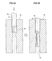
- FIGS. 4A and 4B are illustrations showing how to form an extruded body
- FIGS. 5A and 5B are illustrations showing how to form a fourth composite material
- FIGS. 6A and 6B are illustrations showing how to carry out a re-forming process
- FIGS. 7A and 7B are illustrations showing a relationship between a cross-section reduction rate and bulge amount
- FIGS. 8A and 8B are illustrations showing a final step of a method of manufacturing the spark plug.
- FIG. 9 is a reference diagram showing a phenomenon wherein a lubricant in an extrusion die is pushed back to the side surface of a medium diameter portion.
- FIG. 1 is a fragmentary sectional view of a spark plug 100 as an embodiment of the invention.
- the right side of an axis O-O shown by the dashed-dotted line presents an external front view
- the left side of the axis O-O presents a sectional view of the spark plug 100 taken on a plane passing through the central axis of the spark plug 100 .
- an axial direction OD of the spark plug 100 in FIG. 1 as an up-down direction in each drawing, the lower side as the leading end side of the spark plug 100 , and the upper side as the rear end side.
- the spark plug 100 includes an insulator 10 as an insulating body, a metal shell 50 , a center electrode 20 , a ground electrode 30 , and a terminal 40 .
- the metal shell 50 has formed therein an insert hole 501 passing therethrough in the axial direction OD.
- the insulator 10 is inserted and held in the insert hole 501 .
- the center electrode 20 is held in the axial direction OD in an axial hole 12 formed in the insulator 10 .
- the leading end portion of the center electrode 20 is exposed on the leading end side of the insulator 10 .
- the ground electrode 30 is joined to the leading end portion of the metal shell 50 .
- the terminal 40 is provided on the rear end side of the center electrode 20 , and the rear end portion of the terminal 40 is exposed on the rear end side of the insulator 10 .
- the insulator 10 is formed by sintering alumina or the like, as well known.
- Insulator 10 has a hollow cylindrical shape in which the axial hole 12 extending in the axial direction OD is formed centered on the axis.
- a flange portion 19 of a largest outside diameter is formed in approximately the center of the insulator 10 in the axial direction OD, and a rear end side barrel portion 18 is formed closer to the rear end side than the flange portion 19 .
- a leading end side barrel portion 17 of an outside diameter smaller than that of the rear end side barrel portion 18 is formed closer to the leading end side than the flange portion 19 .
- An insulator nose length portion 13 of an outside diameter smaller than that of the leading end side barrel portion 17 is formed still closer to the leading end side than the leading end side barrel portion 17 .
- the insulator nose length portion 13 decreases in diameter toward the leading end side, and is exposed in a combustion chamber of an internal combustion engine when the spark plug 100 is mounted in an engine head 200 of the internal combustion engine.
- the metal shell 50 is a hollow cylindrical metallic part for fixing the spark plug 100 in the engine head 200 of the internal combustion engine.
- the metal shell 50 holds the insulator 10 in such a way so as to surround a region of the insulator 10 from one portion of the rear end side barrel portion 18 of the insulator 10 to the insulator nose length portion 13 . That is, the metal shell 50 is configured in such a way that the insulator 10 is inserted into the insert hole 501 of the metal shell 50 , and the leading end and rear end of the insulator 10 are exposed from the leading end and rear end respectively of the metal shell 50 .
- the metal shell 50 being formed from low-carbon steel, is plated all over with nickel, zinc, or the like.
- a tool engagement portion 51 of a hexagonal prism shape with which a spark plug wrench (not shown) is engaged is provided at the rear end portion of the metal shell 50 .
- the metal shell 50 includes a mounting threaded portion 52 , on which screw threads are formed, for threaded engagement with a mounting threaded bore 201 of the engine head 200 provided in an upper portion of the internal combustion engine.
- a flange-like seal portion 54 is formed between the tool engagement portion 51 and mounting threaded portion 52 of the metal shell 50 .
- An annular gasket 5 formed by bending a plate body, is fitted over a thread neck 59 between the mounting threaded portion 52 and seal portion 54 .
- the gasket 5 changes in shape by being squeezed by a seating surface 55 of the seal portion 54 and an opening peripheral portion 205 of the mounting threaded bore 201 when the spark plug 100 is mounted in the engine head 200 .
- a space between the spark plug 100 and engine head 200 is sealed by the change in shape of the gasket 5 , preventing an air leakage from within the internal combustion engine via the mounting threaded bore 201 .
- a thin-walled caulked portion 53 is provided closer to the rear end side than the tool engagement portion 51 of the metal shell 50 . Also, a compressively deformed portion 58 as thin-walled as the caulked portion 53 is provided between the seal portion 54 and tool engagement portion 51 .
- Circular ring members 6 and 7 are interposed between an inner peripheral surface of the metal shell 50 and an outer peripheral surface of the rear end side barrel portion 18 of the insulator 10 , each of which ranges from the tool engagement portion 51 to the caulked portion 53 .
- a space between the two ring members 6 and 7 is filled with talc 9 powder.
- the compressively deformed portion 58 is compressively deformed by the caulked portion 53 being pressed toward the leading end side in such a way as to be bent inward and, owing to the compressive deformation of the compressively deformed portion 58 , the insulator 10 is pressed toward the leading end side, in the metal shell 50 , across the ring members 6 and 7 and talc 9 .
- an insulator shoulder 15 positioned at the base end of the insulator 10 nose length portion 13 is pressed across an annular plate packing 8 against an in-metal-shell shoulder 56 formed in a position of the mounting threaded portion 52 on the inner periphery of the metal shell 50 , thus integrating the metal shell 50 and insulator 10 .
- the airtightness between the metal shell 50 and insulator 10 is maintained by the plate packing 8 , preventing an outflow of combustion gas. Also, owing to the pressure, the talc 9 is compressed in the axial direction OD, increasing the airtightness in the metal shell 50 .
- FIG. 2 is a fragmentary sectional view of the center electrode 20 .
- the center electrode 20 is a bar-like electrode having a structure wherein a core 22 made of copper or a copper-based alloy, superior in thermal conductivity to an electrode base material 21 .
- Core 22 is buried inside the electrode base material 21 , which is formed from nickel or a nickel-based alloy, such as Inconel (trade name) 600 .
- a flange-like large diameter portion 23 is formed in a rear end portion of the center electrode 20 . Flange-like large diameter portion 23 is placed in position by abutting from the rear end side against an in-axial-hole shoulder 14 which reduces the diameter of the axial hole 12 from the rear end side toward the leading end side.
- a barrel portion 24 smaller in diameter than the large diameter portion 23 , is formed on the leading end side of the large diameter portion 23 . Also, a first small diameter portion 25 , smaller in diameter than the barrel portion 24 , is formed closer to the leading end side than the barrel portion 24 , and a second small diameter portion 26 , smaller in diameter than the first small diameter portion 25 , is formed still closer to the leading end side than the first small diameter portion 25 . The second small diameter portion 26 is protruded on the leading end side beyond the leading end of the insulator 10 , and forms a spark gap with the ground electrode 30 , to be described hereafter.
- the barrel portion 24 is disposed closer to the leading end side than the in-axial-hole shoulder 14 in the axial hole 12 .
- the center electrode 20 with this kind of structure is disposed closest to the leading end side in the axial hole 12 of the insulator 10 , and a glass seal body 4 and a ceramic resistor 3 are disposed on the rear end side of the center electrode 20 . Then, the center electrode 20 is electrically connected to the terminal 40 , disposed at the rear end of the axial hole 12 , via the glass seal body 4 and ceramic resistor 3 .
- a high voltage cable (not shown) is connected to the terminal 40 via a plug cap (not shown), and a high voltage is applied to the terminal 40 .
- the ground electrode 30 ( FIG. 1 ) is configured from a metal with high corrosion resistance, and a nickel alloy is used as one example of the metal.
- the base end of the ground electrode 30 is welded to the leading end face of the metal shell 50 .
- the leading end portion of the ground electrode 30 is bent so as to be opposed, on the axis O-O, to the leading end face of the center electrode 20 in the axial direction OD.
- FIGS. 3A to 3I are illustrations showing all steps of the method of manufacturing the center electrode 20 .
- a wire rod of nickel, a nickel alloy, or the like, superior in thermal resistance and corrosion resistance is cut to a predetermined length, and a bottomed cylindrical cup member 60 is formed by carrying out a cold forging.
- a wire rod of copper, a copper alloy, or the like, superior in thermal conductivity to the cup member 60 is cut to a predetermined length, and a columnar shaft center 62 having a flange-like head portion 61 at the rear end is formed by carrying out a cold forging (step A).
- the shaft center 62 is pressed into the cup member 60 with a predetermined load (step B).
- a first composite material 63 is formed, as shown in FIG. 3B .
- the cup member 60 is the source of the electrode base material 21 shown in FIG. 2
- the shaft center 62 is the source of the core 22 shown in FIG. 2 .
- a lubricant is injected into an extrusion die as necessary.
- the first composite material 63 is inserted into a round, cylindrical hole 81 of an extrusion die 80 , and extruded by being pressed in by a punch 82 (step C).
- the leading end side portion of the first composite material 63 is reduced in diameter, forming a round bar-like extruded body 64 , as shown in FIG. 3C .
- a round bar-like medium diameter portion 65 smaller in diameter than the first composite material 63 is formed in the leading end side portion of the extruded body 64 , and a flange-like head portion 66 not extruded is formed in the rear end side portion.
- step D On the extruded body 64 being removed from the extrusion die 80 , one rear end side portion of the extruded body 64 including the head portion 66 is cut off, thereby forming a second composite material 67 formed of the medium diameter portion 65 , as shown in FIG. 3D (step D).
- the second composite material 67 corresponds to a “cylindrical electrode member” in an application example, and the step A to step D correspond to “first step.”
- the extruded body 64 is further extruded and reduced in diameter (step E), and the head portion thereof is cut off (step F), thereby generating a third composite material 68 of which the medium diameter portion 65 has a diameter a 1 (for example, 1.9 mm).
- step E and step F correspond to “second step” in the application example.
- the third composite material 68 is inserted into a round hole 84 of an extrusion die 83 , and extruded by being pressed in by a punch 85 , thus further reducing the diameter of the leading end portion of the medium diameter portion 65 , as shown in FIGS. 5A and 5B (step G).
- a fourth composite material 69 having the second small diameter portion 26 of a diameter c (for example, 1.6 mm) is formed at the leading end of the medium diameter portion 65 , as shown in FIG. 3G .
- the step G corresponds to a “third step” in the application example.
- the second small diameter portion 26 when the second small diameter portion 26 is formed at the leading end of the medium diameter portion 65 , a phenomenon may occur wherein the medium diameter portion 65 of the fourth composite material 69 bulges toward the outer periphery in a slight clearance CL ( FIG. 5 ) between the round hole 84 of the extrusion die 83 and the fourth composite material 69 due to a load from the punch 85 , and the diameter of the medium diameter portion 65 becomes a diameter a 2 larger than the diameter a 1 partially (in many cases, at the rear end portion) or as a whole.
- a re-forming process for returning the diameter of the medium diameter portion 65 of the fourth composite material 69 from the diameter a 2 to the diameter a 1 is carried out in order that the amount of the bulge E (the difference between the diameter a 2 and diameter a 1 ) is kept within a predetermined tolerance (in the embodiment, 0.010 mm) (step H).
- the step H corresponds to a “fourth step” in the application example.
- FIGS. 6A and 6B are illustrations showing how to carry out the re-forming process.
- the fourth composite material 69 is inserted into a round hole 87 of an extrusion die 86 and pressed in by a punch 88 , and by thus extruding the medium diameter portion 65 , the diameter of the medium diameter portion 65 is re-formed into the diameter a 1 from the diameter a 2 .
- the medium diameter portion 65 re-formed in this way forms the barrel portion 24 of the center electrode 20 in FIG. 2 .
- the re-forming process is carried out when a cross-section reduction rate R of the medium diameter portion 65 when forming the second small diameter portion 26 is 30% or more.
- R [%] ( S 1 ⁇ S 2)/ S 1 ⁇ 100 Equation 1
- FIGS. 7A and 7B are illustrations showing a relationship between the cross-section reduction rate R and bulge amount E.
- the relationship between the cross-section reduction rate R and bulge amount E is shown in tabular form in FIG. 7A , and in graph form in FIG. 7B .
- the bulge amounts E in accordance with the cross-section reduction rates R of various samples wherein the diameter a 1 of the medium diameter portion 65 of the third composite material 68 ranges from 1.5 mm to 3.0 mm are obtained by experiments.
- Each bulge amount E shown in FIGS. 7A and 7B is the mean value of the bulge amounts E of the samples at the cross-section reduction rates R. According to the experimental results shown in FIGS.
- the fourth composite material 69 is inserted into a round hole 90 of an extrusion die 89 for forming the first small diameter portion 25 , and is extruded by being pressed in by a punch 91 .
- a die for forming the large diameter portion 23 of the center electrode 20 (step I in FIG. 3I ) is formed on the leading end face of punch 91 .
- the first small diameter portion 25 of a diameter b (for example, 1.7 mm) is smaller than that of the medium diameter portion 65 and is larger than that of the second small diameter portion 26 .
- First small diameter portion 25 is formed between the medium diameter portion 65 and second small diameter portion 26 of the fourth composite material 69 .
- the large diameter portion 23 is formed at the rear end of the medium diameter portion 65 .
- the step I is carried out with a slight bulge 70 formed at the rear end of the fourth composite material 69 still remaining in the re-forming process of the step H, but may be carried out after the bulge 70 is cut off.
- the fourth composite material 69 manufactured in the way heretofore described is used as the center electrode 20 shown in FIG. 2 in manufacturing the spark plug 100 .
- the center electrode 20 is inserted into the axial hole 12 of the insulator 10 from the rear end side.
- a glass seal material is inserted from above the center electrode 20 .
- the terminal 40 is pressed in from above the glass seal material.
- the insulator 10 is mounted in the metal shell 50 to which the bar-like ground electrode 30 has been welded in advance.
- the space between the insulator 10 and the caulked portion 53 of the metal shell 50 is packed with the ring members 6 and 7 and talc 9 , and the caulked portion 53 is caulked from the rear end side.
- the ground electrode 30 is bent, thereby completing the spark plug 100 .
- the medium diameter portion 65 is re-formed, thereby forming the barrel portion 24 of the center electrode 20 . Because of this, it is possible to substantially improve the dimensional accuracy of the diameter of the barrel portion 24 of the central electrode 20 . As a result of this, it is possible to prevent, for example, a crack occurring in the insulator 10 due to a bulge of the barrel portion 24 . Also, as it is possible to uniform the diameter of the barrel portion 24 in the axial direction, it is possible to improve the conductivity of heat from the center electrode to the insulator, enabling a suppression of an abnormal heat generation of the center electrode.
- the re-formation of the medium diameter portion 65 is carried out in the way heretofore described, it is possible to secure a sufficient clearance of the round hole of the extrusion die with which the medium diameter portion 65 is formed in the step F of FIG. 3F . Because of this, it is possible to reduce frictional resistance when extruding. As a result of this, it is possible to easily form the third composite material 68 , and it is possible to reduce a load placed on the extrusion die.
- the medium diameter portion 65 is re-formed in the way heretofore described, the dimensional accuracy of the outside diameter of the fourth composite material 69 inserted into the extrusion die 89 for implementing the final step I is improved. Because of this, defective insertions of the fourth composite material 69 into the extrusion die 89 decrease, enabling an improvement in yield.
- the second small diameter portion 26 which is smaller in diameter and is positioned closer to the leading end side than the first small diameter portion 25 , is formed before the first small diameter portion 25 . Because of this, it is possible to suppress, for example, a phenomenon, which may occur when the first small diameter portion 25 is formed earlier, wherein a lubricant in the extrusion die is pushed back to the side surface of the medium diameter portion 65 , as shown in FIG. 9 . As a result of this, it is possible to prevent the side surface of the medium diameter portion 65 from narrowing due to the existence of the lubricant.
- the re-forming process of returning the diameter a 2 of the bulged medium diameter portion 65 to the original diameter a 1 is carried out.
- the diameter of the third composite material 68 before the re-forming process may be a diameter larger than the diameter a 1 after the re-forming process. That is, a configuration may be adopted wherein the diameter of the medium diameter portion 65 is formed to be slightly large in steps E and F of FIGS. 3E and 3F , and the diameter of the medium diameter portion 65 is accurately formed in the step H after the formation of the second small diameter portion 26 .
- the second small diameter portion 26 is formed earlier than the first small diameter portion 25 , but the first small diameter portion 25 may be formed earlier. In this case, it is preferable to regulate the dimensions of the composite materials and dies so that a reduction in diameter of the side surface of the medium diameter portion 65 does not occur due to the heretofore described pushing back of the lubricant.
- two steps are formed on the center electrode 20 , but it is also possible to omit one of them. Also, three or more steps may be formed.
- the third composite material 68 may be formed by one extrusion.
Landscapes
- Engineering & Computer Science (AREA)
- Manufacturing & Machinery (AREA)
- Spark Plugs (AREA)
Abstract
Description
R[%]=(S1−S2)/S1×100 Equation 1
Claims (2)
Applications Claiming Priority (3)
| Application Number | Priority Date | Filing Date | Title |
|---|---|---|---|
| JP2010-270448 | 2010-12-03 | ||
| JPJP2010-270448 | 2010-12-03 | ||
| JP2010270448A JP5144738B2 (en) | 2010-12-03 | 2010-12-03 | Manufacturing method of center electrode and spark plug |
Publications (2)
| Publication Number | Publication Date |
|---|---|
| US20120142244A1 US20120142244A1 (en) | 2012-06-07 |
| US8591276B2 true US8591276B2 (en) | 2013-11-26 |
Family
ID=45372201
Family Applications (1)
| Application Number | Title | Priority Date | Filing Date |
|---|---|---|---|
| US13/308,921 Expired - Fee Related US8591276B2 (en) | 2010-12-03 | 2011-12-01 | Method of manufacturing center electrode and spark plug |
Country Status (3)
| Country | Link |
|---|---|
| US (1) | US8591276B2 (en) |
| EP (1) | EP2461439B1 (en) |
| JP (1) | JP5144738B2 (en) |
Families Citing this family (2)
| Publication number | Priority date | Publication date | Assignee | Title |
|---|---|---|---|---|
| JP4719191B2 (en) * | 2007-07-17 | 2011-07-06 | 日本特殊陶業株式会社 | Spark plug for internal combustion engine |
| JP2018029005A (en) * | 2016-08-17 | 2018-02-22 | 日本特殊陶業株式会社 | Spark plug |
Citations (2)
| Publication number | Priority date | Publication date | Assignee | Title |
|---|---|---|---|---|
| JPH08213150A (en) | 1995-02-08 | 1996-08-20 | Ngk Spark Plug Co Ltd | Method for manufacturing composite electrode for spark plug |
| US20060028108A1 (en) * | 2004-08-06 | 2006-02-09 | Denso Corporation | Spark plug with high capability to ignite air-fuel mixture |
Family Cites Families (4)
| Publication number | Priority date | Publication date | Assignee | Title |
|---|---|---|---|---|
| US4684352A (en) * | 1985-03-11 | 1987-08-04 | Champion Spark Plug Company | Method for producing a composite spark plug center electrode |
| JP2892119B2 (en) * | 1990-08-07 | 1999-05-17 | 日本特殊陶業株式会社 | Method of manufacturing composite electrode for spark plug |
| JP4220218B2 (en) * | 2002-10-25 | 2009-02-04 | 株式会社デンソー | Manufacturing method of center electrode for spark plug |
| US7896720B2 (en) * | 2006-03-14 | 2011-03-01 | Ngk Spark Plug Co., Ltd. | Method of producing spark plug, and spark plug |
-
2010
- 2010-12-03 JP JP2010270448A patent/JP5144738B2/en not_active Expired - Fee Related
-
2011
- 2011-12-01 US US13/308,921 patent/US8591276B2/en not_active Expired - Fee Related
- 2011-12-05 EP EP11191877.7A patent/EP2461439B1/en not_active Not-in-force
Patent Citations (2)
| Publication number | Priority date | Publication date | Assignee | Title |
|---|---|---|---|---|
| JPH08213150A (en) | 1995-02-08 | 1996-08-20 | Ngk Spark Plug Co Ltd | Method for manufacturing composite electrode for spark plug |
| US20060028108A1 (en) * | 2004-08-06 | 2006-02-09 | Denso Corporation | Spark plug with high capability to ignite air-fuel mixture |
Non-Patent Citations (1)
| Title |
|---|
| English Translation of JP 8-213150 A to Ando Minoru (Aug. 20, 1996). * |
Also Published As
| Publication number | Publication date |
|---|---|
| EP2461439B1 (en) | 2018-06-13 |
| US20120142244A1 (en) | 2012-06-07 |
| JP5144738B2 (en) | 2013-02-13 |
| JP2012119264A (en) | 2012-06-21 |
| EP2461439A2 (en) | 2012-06-06 |
| EP2461439A3 (en) | 2014-11-19 |
Similar Documents
| Publication | Publication Date | Title |
|---|---|---|
| US7914353B2 (en) | Spark plug and method for manufacturing the same | |
| US8963407B2 (en) | Spark plug | |
| US20090189502A1 (en) | Method of producing spark plug, and spark plug | |
| JP4889768B2 (en) | Spark plug and manufacturing method thereof | |
| JP6482719B2 (en) | Spark plug | |
| US20100242888A1 (en) | Spark plug for internal combustion engine | |
| US8591276B2 (en) | Method of manufacturing center electrode and spark plug | |
| US9054501B2 (en) | Spark plug | |
| EP2833069A1 (en) | Glow plug and method for manufacturing same | |
| US9889496B2 (en) | Method for manufacturing metal fitting, method for manufacturing spark plug, and method for manufacturing sensor | |
| US9660423B2 (en) | Spark plug having an electrode structure that effectively suppresses flashover | |
| JP5639118B2 (en) | Manufacturing method of spark plug | |
| JP2020202111A (en) | Manufacturing method of tubular metal fitting | |
| US9599341B2 (en) | Glow plug and method for manufacturing same | |
| JP2013101805A (en) | Method for manufacturing spark plug | |
| JP6077397B2 (en) | Manufacturing method of spark plug | |
| JP5960869B1 (en) | Spark plug | |
| JP6335770B2 (en) | Method for manufacturing an insulator for a spark plug | |
| JP5642019B2 (en) | Spark plug electrode member and spark plug manufacturing method | |
| JP5783950B2 (en) | Manufacturing method of spark plug | |
| JP5451676B2 (en) | Manufacturing method of spark plug | |
| JP2014216277A (en) | Spark plug manufacturing method |
Legal Events
| Date | Code | Title | Description |
|---|---|---|---|
| AS | Assignment |
Owner name: NGK SPARK PLUG CO., LTD., JAPAN Free format text: ASSIGNMENT OF ASSIGNORS INTEREST;ASSIGNOR:OCHIAI, SATORU;REEL/FRAME:027314/0531 Effective date: 20111130 |
|
| STCF | Information on status: patent grant |
Free format text: PATENTED CASE |
|
| FPAY | Fee payment |
Year of fee payment: 4 |
|
| MAFP | Maintenance fee payment |
Free format text: PAYMENT OF MAINTENANCE FEE, 8TH YEAR, LARGE ENTITY (ORIGINAL EVENT CODE: M1552); ENTITY STATUS OF PATENT OWNER: LARGE ENTITY Year of fee payment: 8 |
|
| FEPP | Fee payment procedure |
Free format text: MAINTENANCE FEE REMINDER MAILED (ORIGINAL EVENT CODE: REM.); ENTITY STATUS OF PATENT OWNER: LARGE ENTITY |
|
| LAPS | Lapse for failure to pay maintenance fees |
Free format text: PATENT EXPIRED FOR FAILURE TO PAY MAINTENANCE FEES (ORIGINAL EVENT CODE: EXP.); ENTITY STATUS OF PATENT OWNER: LARGE ENTITY |
|
| STCH | Information on status: patent discontinuation |
Free format text: PATENT EXPIRED DUE TO NONPAYMENT OF MAINTENANCE FEES UNDER 37 CFR 1.362 |
|
| FP | Lapsed due to failure to pay maintenance fee |
Effective date: 20251126 |