US8579479B2 - Warning lamp for an aircraft - Google Patents
Warning lamp for an aircraft Download PDFInfo
- Publication number
- US8579479B2 US8579479B2 US12/996,831 US99683109A US8579479B2 US 8579479 B2 US8579479 B2 US 8579479B2 US 99683109 A US99683109 A US 99683109A US 8579479 B2 US8579479 B2 US 8579479B2
- Authority
- US
- United States
- Prior art keywords
- cover portion
- cooling body
- rear cover
- cooling
- front cover
- Prior art date
- Legal status (The legal status is an assumption and is not a legal conclusion. Google has not performed a legal analysis and makes no representation as to the accuracy of the status listed.)
- Expired - Fee Related, expires
Links
Images


Classifications
-
- B—PERFORMING OPERATIONS; TRANSPORTING
- B64—AIRCRAFT; AVIATION; COSMONAUTICS
- B64D—EQUIPMENT FOR FITTING IN OR TO AIRCRAFT; FLIGHT SUITS; PARACHUTES; ARRANGEMENT OR MOUNTING OF POWER PLANTS OR PROPULSION TRANSMISSIONS IN AIRCRAFT
- B64D47/00—Equipment not otherwise provided for
- B64D47/02—Arrangements or adaptations of signal or lighting devices
- B64D47/06—Arrangements or adaptations of signal or lighting devices for indicating aircraft presence
-
- F—MECHANICAL ENGINEERING; LIGHTING; HEATING; WEAPONS; BLASTING
- F21—LIGHTING
- F21S—NON-PORTABLE LIGHTING DEVICES; SYSTEMS THEREOF; VEHICLE LIGHTING DEVICES SPECIALLY ADAPTED FOR VEHICLE EXTERIORS
- F21S43/00—Signalling devices specially adapted for vehicle exteriors, e.g. brake lamps, direction indicator lights or reversing lights
- F21S43/10—Signalling devices specially adapted for vehicle exteriors, e.g. brake lamps, direction indicator lights or reversing lights characterised by the light source
- F21S43/13—Signalling devices specially adapted for vehicle exteriors, e.g. brake lamps, direction indicator lights or reversing lights characterised by the light source characterised by the type of light source
- F21S43/14—Light emitting diodes [LED]
-
- F—MECHANICAL ENGINEERING; LIGHTING; HEATING; WEAPONS; BLASTING
- F21—LIGHTING
- F21V—FUNCTIONAL FEATURES OR DETAILS OF LIGHTING DEVICES OR SYSTEMS THEREOF; STRUCTURAL COMBINATIONS OF LIGHTING DEVICES WITH OTHER ARTICLES, NOT OTHERWISE PROVIDED FOR
- F21V29/00—Protecting lighting devices from thermal damage; Cooling or heating arrangements specially adapted for lighting devices or systems
- F21V29/50—Cooling arrangements
- F21V29/70—Cooling arrangements characterised by passive heat-dissipating elements, e.g. heat-sinks
- F21V29/74—Cooling arrangements characterised by passive heat-dissipating elements, e.g. heat-sinks with fins or blades
-
- F—MECHANICAL ENGINEERING; LIGHTING; HEATING; WEAPONS; BLASTING
- F21—LIGHTING
- F21V—FUNCTIONAL FEATURES OR DETAILS OF LIGHTING DEVICES OR SYSTEMS THEREOF; STRUCTURAL COMBINATIONS OF LIGHTING DEVICES WITH OTHER ARTICLES, NOT OTHERWISE PROVIDED FOR
- F21V29/00—Protecting lighting devices from thermal damage; Cooling or heating arrangements specially adapted for lighting devices or systems
- F21V29/50—Cooling arrangements
- F21V29/70—Cooling arrangements characterised by passive heat-dissipating elements, e.g. heat-sinks
- F21V29/83—Cooling arrangements characterised by passive heat-dissipating elements, e.g. heat-sinks the elements having apertures, ducts or channels, e.g. heat radiation holes
-
- B—PERFORMING OPERATIONS; TRANSPORTING
- B64—AIRCRAFT; AVIATION; COSMONAUTICS
- B64D—EQUIPMENT FOR FITTING IN OR TO AIRCRAFT; FLIGHT SUITS; PARACHUTES; ARRANGEMENT OR MOUNTING OF POWER PLANTS OR PROPULSION TRANSMISSIONS IN AIRCRAFT
- B64D2203/00—Aircraft or airfield lights using LEDs
-
- F—MECHANICAL ENGINEERING; LIGHTING; HEATING; WEAPONS; BLASTING
- F21—LIGHTING
- F21W—INDEXING SCHEME ASSOCIATED WITH SUBCLASSES F21K, F21L, F21S and F21V, RELATING TO USES OR APPLICATIONS OF LIGHTING DEVICES OR SYSTEMS
- F21W2107/00—Use or application of lighting devices on or in particular types of vehicles
- F21W2107/30—Use or application of lighting devices on or in particular types of vehicles for aircraft
-
- F—MECHANICAL ENGINEERING; LIGHTING; HEATING; WEAPONS; BLASTING
- F21—LIGHTING
- F21W—INDEXING SCHEME ASSOCIATED WITH SUBCLASSES F21K, F21L, F21S and F21V, RELATING TO USES OR APPLICATIONS OF LIGHTING DEVICES OR SYSTEMS
- F21W2111/00—Use or application of lighting devices or systems for signalling, marking or indicating, not provided for in codes F21W2102/00 – F21W2107/00
-
- F—MECHANICAL ENGINEERING; LIGHTING; HEATING; WEAPONS; BLASTING
- F21—LIGHTING
- F21Y—INDEXING SCHEME ASSOCIATED WITH SUBCLASSES F21K, F21L, F21S and F21V, RELATING TO THE FORM OR THE KIND OF THE LIGHT SOURCES OR OF THE COLOUR OF THE LIGHT EMITTED
- F21Y2115/00—Light-generating elements of semiconductor light sources
- F21Y2115/10—Light-emitting diodes [LED]
Definitions
- the invention involves a warning lamp for an aircraft and particularly a warning lamp for an airplane which emits a red strobe light.
- warning lights On the outside of an airplane or another aircraft, there are numerous lights, such as warning lights and position or navigational lights, which emit their light within statutorily specified spatial angles.
- warning lamps which emit their light in the form of strobe lights in white or red colors.
- warning lights on the exterior of an aircraft were equipped with Xenon lamps as lighting.
- These known warning lamps included housing with a domed, light permeable cover which is exposed to the surrounding air when the warning lamp is mounted on the aircraft.
- the covers of the known warning lamps have a largely drop or egg-shaped form with a frontal cover area which points into the direction of flight and a rear cover area which points in the opposite direction.
- the cover is fastened on a lower part of the housing—which is mounted on the aircraft—with a mounting element in the form of a ring which surrounds the edge of the cover and from which the cover protrudes.
- LEDs have found increasing use in exterior lighting on aircraft. These light emitting semiconductor diodes have a significantly longer service life and are not nearly as subject to breakdowns as Xenon lamps.
- LEDs furthermore require electronic control units which are smaller and weigh less than the switching electronics of Xenon strobe lights.
- the heat sensitivity of LEDs is problematic.
- their emission properties are not necessarily suited to use in warning or positional lights of airplanes. Therefore, the currently available LED warning lights with a light output that is comparable to Xenon strobe lights are still very large and heavy in order to combine the desired emission properties of the warning lights with good heat removal.
- WO-A-2006/091225 describes a warning lamp for aircraft which is equipped with a cooling body that has cooling blades which are exposed to an airflow that moves along the housing of the warning lamp when the aircraft is in flight.
- the cooling body of the known warning lamp serves to remove the loss output that is generated by the LEDs in the form of heat.
- the cooling body is located on the cover, which is not problematic, since the warning lamp must emit its strobe light largely throughout 360 degrees laterally and upwards at an angle, that is, directly over the warning light—that is, in a location where the cooling body/cooling blades of the known warning lamp are placed and where no light need be emitted.
- warning lamp is, however, seen in that it is formed as a rotationally symmetric body similar to a blunt cone with no optimal aerodynamic properties, thereby negatively influencing air resistance (parasitic drag).
- the object of the invention is to create a warning lamp for an aircraft which uses LED lights and whose housing or cover has an aerodynamically beneficial form, wherein all requirements for spatial distribution of light in warning lamps for aircraft are fulfilled.
- the invention suggests a warning lamp for aircraft which is provided with
- the invention provides that
- the warning lamp in accordance with the invention has a housing which has a lower part for fastening to the aircraft and a light permeable cover.
- the light permeable cover is held against the lower part of the housing/against the aircraft with a ring shaped mounting element.
- the mounting element surrounds the edge of the cover, which extends in a dome-like manner in an upwards direction.
- the cover may have an aerodynamic form which is, for instance, drop or egg-shaped or bionic, that is, derived from the streamlined shapes of living beings.
- the cover of the warning lamp is formed in two parts and includes a frontal cover element that points in the direction of flight and is made from a light permeable first material, and a rear cover element that points in the direction opposing the direction of flight and is made of a light permeable second material which is similar to or different from the first material.
- a frontal cover element that points in the direction of flight and is made from a light permeable first material
- a rear cover element that points in the direction opposing the direction of flight and is made of a light permeable second material which is similar to or different from the first material.
- an interim piece consisting—so to speak—of a cooling body or parts of a cooling body, wherein the surface of the cooling body together with the two cover elements form the aerodynamic shape or the external contours of the cover, that is, the area of the warning lamp which protrudes from the lower part of the housing.
- the cooling body separates the two cover elements from each other and possesses an upper area that is perpendicular to the direction of flight as well as adjoining opposite side areas which are lateral to the direction of flight.
- the cooling body's side parts are advantageously surrounded/enclosed by the mounting element.
- the cooling body with its cooling surfaces that are exposed to the airflow are located in the upper area and in the side areas of the warning lamp. According to current regulations, the warning lamp does not have to emit light directly upwards.
- Light emission on the side areas of the cooling surface of the cooling body is realized by LED lamps which—looking in the direction of flight—are arranged bilaterally, that is, in the direction of flight both before and behind the side areas within the two cover elements, and emit light to the side and upwards at an angle.
- the benefit of the structure of the warning lamp in accordance with the invention with two cover elements as a light permeable cover is that one can now freely choose the transparent materials for the two cover elements.
- the frontal cover element which points in the direction of flight should preferably be made from a suitable erosion resistant material such as glass
- the transparent material for the rear cover element could be made from a less erosion resistant material such as plastic.
- the rear cover element that is made from plastic may possess light control areas in the form of areas that are shaped inwards and through which the light can particularly be intensified in the rearward pointing emission directions that are at a small angle from the direction of flight, or which can be used to increase its intensities.
- the materials of both cover elements may, however, also be the same.
- the benefit of the concept in the invention is furthermore that the known warning lamps which are based on Xenon light technology can be changed without problems, since the warning lamp in accordance with the invention can have the same drop or egg formed shape as the known warning lamps.
- the warning lamp in accordance with the invention profits from the low likelihood of failures and the long service life of LED lamps.
- warning lights for aircraft do not have to emit light directly above the cover of the warning light. Rather, the light must be emitted all around throughout 360 degrees as well as slightly angled upwards. This means that the upper area of the cooling surface of the cooling body between the frontal and rear cover areas can have a relatively large extent, while the two side areas of the cooling surface which extend to the mounting element can be more slender or narrow. This can be realized without problems when using the structural concept of the warning lamp as in the invention.
- the thermal loss output of the LEDs is largely removed through the cooling surface of the cooling body that is exposed to the airflow. Furthermore, in an advantageous development of the invention, the cooling body, on the segments which form the side areas of the cooling surface, can be thermally linked to the assembly element. In this way, heat is also drained through the mounting element and if applicable, from there through the exterior skin of the aircraft.
- the multi-part structure of the domed or cap-shaped cover in accordance with the invention means that the transitions between the cooling body on the one hand and the two cover elements on the other hand are produced in a weather resistant and particularly moisture resistant form.
- the cooling body on its frontal end which points in the direction of flight as well as its rear end which points in the direction opposite from the direction of flight, has an edge which interlinks with an edge of the rear cover element or is formed so that they overlap or engage with each other, wherein there is a sealant between the edges in each case.
- FIG. 1 a side view of a warning lamp with largely drop or egg-shaped aerodynamically favorable external contours of their cover and cooling body surface configuration
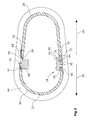
- FIG. 2 a cross-section along the line II-II of FIG. 1 through the cover and the cooling body, without showing the lower part of the housing of the warning lamp.
- FIG. 1 shows a side view with a partial section of a strobe lamp warning lamp 1 , which has a housing 10 with an upper part 12 and a plate-formed lower part 14 , which, when the warning lamp 1 is mounted, is located on the exterior skin of an aircraft, such as an airplane.
- the upper part 12 of the housing 10 which protrudes from the lower part 14 includes a two-part light permeable cover 16 as well as a cooling body 18 .
- the cover 16 possesses a frontal light permeable cover element 22 which points in the direction of flight 20 and is made of, e.g., glass or with a glass-hard exterior surface 24 and is furthermore equipped with a rear cover element 28 that points opposite the direction of flight 20 , that is, in the direction of the arrow 26 , and is made from transparent plastic, with an outer surface 30 .
- the cooling body 18 whose exterior surface forms the cooling surface 32 , possibly with tongues or grooves 34 that run parallel to the direction of flight 20 and which form the drop, dome or egg shaped external contours of the warning lamp 1 together with the exterior surfaces 24 , 30 of the cover 16 , is located between these two cover elements 22 , 28 .
- the cooling surface 32 of the cooling body 18 herein extends into the direction of flight 20 as seen throughout 180 degrees and has an upper area 38 that points up in the direction of the arrow 36 and adjacent opposing side areas 40 which are oriented laterally to the direction of flight 20 .
- This three-part cover 16 with the cooling surface 32 is surrounded at its surrounding edge 41 that lies on the lower part 14 by a ring-shaped or flange-like mounting element 44 which is made of metal, and which is, for instance, bolted to the lower part 14 of the housing 10 of the warning lamp 1 .
- the cooling body 18 is larger in its upper area 38 between the frontal and rear cover elements 22 , 28 than within its opposing side areas 40 .
- the cooling body should have a comparably large cooling surface 32 . Since the warning lamp 1 does not have to emit light upwards, that is, in the direction of the arrow 36 , the cooling body can have a relatively large area in the region 38 of its cooling surface 32 .
- the cooling surface 32 is made narrower in the side areas 40 , so that LEDs 42 can provide sufficient light emission from this location, meeting the statutory requirements in terms of intensity and distribution.
- the cooling body 18 can be thermally linked to the mounting element 44 in an advantageous manner. This is shown in FIG. 1 at 45 .
- the mounting element 44 also consists of a metal, particularly a metal alloy, which is preferably an aluminum alloy.
- the lower part 14 of the housing 10 of the warning lamp 1 is also preferably made from a metallic material.
- the warning lamp 1 has other LEDs 46 to emit light in the direction of flight 20 as well as in the required height and side angles in relation to it.
- other LEDs 48 ensure light emission in the direction that opposes the direction of flight (that is, in the direction of the arrow 26 ) as well as the required height and side angles from it.
- FIG. 1 does not by far show all LEDs which are required for the required light distribution and light intensity distribution of the warning lamp 1 .
- the rear cover element 28 possesses internal light inclusion surfaces 54 , 56 opposite which LEDs 58 , 60 are arranged, which, in turn, are arranged on the cooling body 18 or the lower part 14 .
- the rear cover element 28 therefore has a partial light conductor function, which specifically makes it possible to adapt and influence the light distribution and light intensity in accordance with statutory requirements and while using as few LEDs as possible.
- warning lamp 1 refers to reflectors which can be assigned to individual LEDs or groups of LEDs. Aside from reflective optical elements (such as the reflectors 62 ), the warning lamp 1 may alternatively or additionally use refractive optical elements such as lenses for light distribution.
- FIG. 2 shows a horizontal section along line II-II of FIG. 1 through the cover 16 , wherein the mounting ring 44 is also shown.
- the cooling body 18 is likewise only partially shown/sectionally shown.
- FIG. 2 shows several variants of a possible mechanical linkage of the cooling body 18 with the frontal and rear cover elements 22 , 28 .
- FIG. 2 top right, shows a possible connection of the rear cover element 28 with the cooling body 18 , wherein both show overlapping edges 64 , 66 with a sealing material 68 arranged between them.
- the outer surface 24 of the rear cover element 28 herein moves back by the distance 70 as compared to the cooling surface 32 in the side areas 40 of the cooling body 18 .
- connection of the cooling body 18 to the frontal and/or rear cover element 22 , 28 may, however, also be made by using a sealing cord 72 with an O cross-section, which is placed into overlapping grooves 74 , 76 of the overlapping edges 64 , 66 of the cooling body 18 and the cover element 22 or 28 .
- FIG. 2 to the left of the cooling body 18 , two other possible variants of the mechanical connection of the cooling body 18 and the cover element 22 or 28 are shown.
- a tongue and groove-like arrangement 78 , 80 is shown, while FIG. 2 at top left shows a configuration comprising cooperating undercut and thickened parts.
- the cover element 22 has a bulging thickened part 82 which is either attached or formed in a single piece and which is placed into a receiving groove 84 with an undercut.
- the mechanical connections of the cooling body 18 as shown in FIG. 2 can be constructed with the two cover elements 22 , 28 regardless of whether the cover elements 22 , 28 are made from glass material, that is, an erosion resistant material, or plastic, that is, a less erosion resistant material. It is also possible to construct the joint of the cover elements 22 , 28 with the cooling body 18 by means of two opposing angled and largely parallel surfaces on the parts to be joined, which allows very good tolerance equalization.
- the rear part as seen in the direction of flight 20 (that is, the cooling body opposite the frontal cover element 20 and the rear cover element 24 opposite the cooling body 18 ) are arranged so that they are shifted inwards. This rearward shift is shown in FIG. 2 at 70 in each case.
- the mechanical connection between the cover elements and the cooling body that it should be designed in accordance with the commonly differing expansion coefficients, hollowing of joints due to erosion and long-term tightness as well as the required shock resistance against foreign objects.
- permanently elastic form fitted connections are particularly suitable for this, as is the case with the variants of the O ring, tongue and groove, and bulge/receiving groove.
Landscapes
- Engineering & Computer Science (AREA)
- General Engineering & Computer Science (AREA)
- Aviation & Aerospace Engineering (AREA)
- Physics & Mathematics (AREA)
- Microelectronics & Electronic Packaging (AREA)
- Optics & Photonics (AREA)
- Arrangement Of Elements, Cooling, Sealing, Or The Like Of Lighting Devices (AREA)
Abstract
Description
-
- a housing which, when the housing is mounted on the aircraft, has a light permeable cover that is exposed to the surrounding air, with a frontal cover area and a rear cover area,
- a mounting element to fasten the cover on the aircraft and/or on a lower part of the housing, wherein an edge of the cover is covered by an edge of the assembly element and protrudes from it,
- a lighting agent with at least one LED (, which is arranged within an area that is delimited by the cover), and
- a cooling body for the (at least one) LED, wherein the cooling body possesses a cooling surface that is exposed to the surrounding air when the housing is mounted on the aircraft.
-
- the frontal cover area is formed by a frontal cover element which is made from a light permeable first material,
- the rear cover area is formed by a rear cover element which is made from a light permeable second material, and
- the cooling body, with separation of the frontal cover element from the rear cover element, is arranged between the two, wherein its cooling surface is a part of the external contours of the housing cover which are provided by the frontal and rear cover elements and comprises both an upper area and connecting side areas that lie opposite each other.
Claims (15)
Priority Applications (1)
| Application Number | Priority Date | Filing Date | Title |
|---|---|---|---|
| US12/996,831 US8579479B2 (en) | 2008-06-23 | 2009-06-19 | Warning lamp for an aircraft |
Applications Claiming Priority (6)
| Application Number | Priority Date | Filing Date | Title |
|---|---|---|---|
| US7484708P | 2008-06-23 | 2008-06-23 | |
| EP08158766 | 2008-06-23 | ||
| EP08158766A EP2138401A1 (en) | 2008-06-23 | 2008-06-23 | Warning light for an aircraft |
| EP08158766.9 | 2008-06-23 | ||
| PCT/EP2009/057675 WO2009156349A1 (en) | 2008-06-23 | 2009-06-19 | Warning lamp for an aircraft |
| US12/996,831 US8579479B2 (en) | 2008-06-23 | 2009-06-19 | Warning lamp for an aircraft |
Publications (2)
| Publication Number | Publication Date |
|---|---|
| US20110261577A1 US20110261577A1 (en) | 2011-10-27 |
| US8579479B2 true US8579479B2 (en) | 2013-11-12 |
Family
ID=39639605
Family Applications (1)
| Application Number | Title | Priority Date | Filing Date |
|---|---|---|---|
| US12/996,831 Expired - Fee Related US8579479B2 (en) | 2008-06-23 | 2009-06-19 | Warning lamp for an aircraft |
Country Status (3)
| Country | Link |
|---|---|
| US (1) | US8579479B2 (en) |
| EP (2) | EP2138401A1 (en) |
| WO (1) | WO2009156349A1 (en) |
Cited By (3)
| Publication number | Priority date | Publication date | Assignee | Title |
|---|---|---|---|---|
| US20190256223A1 (en) * | 2018-02-16 | 2019-08-22 | Goodrich Lighting Systems Gmbh | Aircraft vertical stabilizer illumination light and aircraft comprising the same |
| JP2020019405A (en) * | 2018-08-01 | 2020-02-06 | 株式会社小糸製作所 | Lighting fixture |
| US20200039661A1 (en) * | 2018-08-01 | 2020-02-06 | Koito Manufacturing Co., Ltd. | Lamp unit |
Families Citing this family (19)
| Publication number | Priority date | Publication date | Assignee | Title |
|---|---|---|---|---|
| EP2325084A1 (en) * | 2009-11-18 | 2011-05-25 | Goodrich Lighting Systems GmbH | Light for a vehicle, in particular an airplane |
| DE202010002772U1 (en) | 2010-02-24 | 2010-07-15 | Thiesen Hardware- Und Software-Design Gmbh | Lamp, in particular position lamp for an aircraft |
| US8740424B2 (en) | 2011-05-20 | 2014-06-03 | Goodrich Lighting Systems Gmbh | Light for an aircraft |
| GB201115025D0 (en) | 2011-08-31 | 2011-10-12 | Airbus Operations Ltd | Integrated wing light |
| EP2574837B1 (en) | 2011-09-28 | 2015-04-29 | Goodrich Lighting Systems GmbH | Light for an aircraft |
| DE202013003441U1 (en) | 2013-04-12 | 2013-06-13 | Thiesen Hardware- Und Software-Design Gmbh | Headlamps, in particular landing lights for aircraft, with light-emitting diodes |
| EP2924340B1 (en) | 2014-03-28 | 2019-05-01 | Goodrich Lighting Systems GmbH | Exterior light unit for an aircraft or other vehicle and aircraft comprising the same |
| EP2960643B1 (en) | 2014-06-27 | 2019-03-13 | Leonardo S.p.A. | System for monitoring a light transparent cover of a light or lamp, especially of an aircraft's external light |
| EP2985229B1 (en) * | 2014-08-14 | 2017-11-15 | Goodrich Lighting Systems GmbH | Exterior aircraft light unit and aircraft comprising the same |
| CN104821126A (en) * | 2015-05-03 | 2015-08-05 | 佛山市三水区希望火炬教育科技有限公司 | Ceramic airship model lamp specialized for teenager national defense scientific literacy education and training and application thereof |
| CN105135311A (en) * | 2015-07-09 | 2015-12-09 | 河南翱翔航空科技有限公司 | Airborne navigation lamp |
| DE102016104113B4 (en) * | 2016-03-07 | 2018-02-15 | Lisa Dräxlmaier GmbH | FLAT LIGHTING DEVICE FOR PARTITION WALLS IN AIRPLANE INTERIORS |
| CN106742001A (en) * | 2016-11-30 | 2017-05-31 | 中国直升机设计研究所 | A kind of airborne alarm control lamp box and the light alarm method with it |
| US11543115B1 (en) | 2021-06-18 | 2023-01-03 | Goodrich Corporation | Heat dissipating light assembly |
| EP4180337B1 (en) * | 2021-11-12 | 2025-03-19 | Goodrich Lighting Systems GmbH & Co. KG | Aircraft beacon light, method of operating an aircraft beacon light, and method of producing an aircraft beacon light |
| US11898717B2 (en) * | 2022-01-05 | 2024-02-13 | Honeywell International Inc. | Light assembly that emits a narrow, unattenuated light beam and attenuated light over broad angles |
| US20250108934A1 (en) * | 2023-10-02 | 2025-04-03 | Christian Nielsen | Anti-collision light for aircraft |
| USD1088313S1 (en) * | 2024-07-23 | 2025-08-12 | Daniel Stenko | Multipurpose external light for an aircraft |
| US12319436B1 (en) * | 2024-11-07 | 2025-06-03 | Christian R Nielsen | Aircraft fuselage lighting pod |
Citations (5)
| Publication number | Priority date | Publication date | Assignee | Title |
|---|---|---|---|---|
| FR2173739A1 (en) | 1972-02-29 | 1973-10-12 | Labinal | |
| WO2000071417A1 (en) | 1999-05-21 | 2000-11-30 | Avimo Limited | Aircraft lighting unit using led's |
| US20020008976A1 (en) | 2000-07-18 | 2002-01-24 | Frank Gronemeier | Led position lamp |
| US20020093820A1 (en) * | 1999-08-04 | 2002-07-18 | Pederson John C. | Led reflector |
| WO2006091225A1 (en) | 2005-01-13 | 2006-08-31 | Honeywell International, Inc. | Body mounted led-based anti-collision light for aircraft |
-
2008
- 2008-06-23 EP EP08158766A patent/EP2138401A1/en not_active Withdrawn
-
2009
- 2009-06-19 WO PCT/EP2009/057675 patent/WO2009156349A1/en not_active Ceased
- 2009-06-19 EP EP09769198.4A patent/EP2296973B1/en active Active
- 2009-06-19 US US12/996,831 patent/US8579479B2/en not_active Expired - Fee Related
Patent Citations (8)
| Publication number | Priority date | Publication date | Assignee | Title |
|---|---|---|---|---|
| FR2173739A1 (en) | 1972-02-29 | 1973-10-12 | Labinal | |
| WO2000071417A1 (en) | 1999-05-21 | 2000-11-30 | Avimo Limited | Aircraft lighting unit using led's |
| US20020149944A1 (en) * | 1999-05-21 | 2002-10-17 | Worsdell Anthony William | In lighting |
| US20020093820A1 (en) * | 1999-08-04 | 2002-07-18 | Pederson John C. | Led reflector |
| US20020008976A1 (en) | 2000-07-18 | 2002-01-24 | Frank Gronemeier | Led position lamp |
| EP1176053A2 (en) | 2000-07-18 | 2002-01-30 | Hella KG Hueck & Co. | Light |
| WO2006091225A1 (en) | 2005-01-13 | 2006-08-31 | Honeywell International, Inc. | Body mounted led-based anti-collision light for aircraft |
| US7645053B2 (en) * | 2005-01-13 | 2010-01-12 | Honeywell International Inc. | Rotationally symmetrical LED-based anti-collision light for aircraft |
Cited By (8)
| Publication number | Priority date | Publication date | Assignee | Title |
|---|---|---|---|---|
| US20190256223A1 (en) * | 2018-02-16 | 2019-08-22 | Goodrich Lighting Systems Gmbh | Aircraft vertical stabilizer illumination light and aircraft comprising the same |
| US10730639B2 (en) * | 2018-02-16 | 2020-08-04 | Goodrich Lighting Systems Gmbh | Aircraft vertical stabilizer illumination light and aircraft comprising the same |
| JP2020019405A (en) * | 2018-08-01 | 2020-02-06 | 株式会社小糸製作所 | Lighting fixture |
| US20200039661A1 (en) * | 2018-08-01 | 2020-02-06 | Koito Manufacturing Co., Ltd. | Lamp unit |
| JP2020019404A (en) * | 2018-08-01 | 2020-02-06 | 株式会社小糸製作所 | Lamp |
| US10843813B2 (en) * | 2018-08-01 | 2020-11-24 | Koito Manufacturing Co., Ltd. | Lamp unit |
| JP7118796B2 (en) | 2018-08-01 | 2022-08-16 | 株式会社小糸製作所 | lamp |
| JP7149127B2 (en) | 2018-08-01 | 2022-10-06 | 株式会社小糸製作所 | lamp |
Also Published As
| Publication number | Publication date |
|---|---|
| EP2296973B1 (en) | 2015-03-04 |
| EP2138401A1 (en) | 2009-12-30 |
| US20110261577A1 (en) | 2011-10-27 |
| EP2296973A1 (en) | 2011-03-23 |
| WO2009156349A1 (en) | 2009-12-30 |
Similar Documents
| Publication | Publication Date | Title |
|---|---|---|
| US8579479B2 (en) | Warning lamp for an aircraft | |
| US7434970B2 (en) | Multi-platform LED-based aircraft rear position light | |
| JP5130192B2 (en) | Vehicle lighting | |
| EP3766743A1 (en) | Vehicular exterior assembly including bumper fascia | |
| US7314296B2 (en) | Multi-platform aircraft forward position light utilizing LED-based light source | |
| EP3670356B1 (en) | Combined forward navigation and anti-collision light for an aircraft and aircraft comprising the same | |
| US11097855B2 (en) | Aircraft beacon light and aircraft comprising an aircraft beacon light | |
| US20100232174A1 (en) | Front Grill | |
| CN107757937B (en) | External aircraft light units, helicopters and airplanes | |
| US9789975B2 (en) | Exterior aircraft light unit and aircraft comprising the same | |
| US10513349B2 (en) | Combined aircraft take-off and tower signal light unit and aircraft comprising the same | |
| EP3583003B1 (en) | Lighting element | |
| EP3401224B1 (en) | Airfield light | |
| US20200232619A1 (en) | Aircraft lamp | |
| US10815004B2 (en) | Lens structure for a light unit, light unit, and aircraft comprising such light unit | |
| EP1923263A1 (en) | Integral rear lamp | |
| US7918592B2 (en) | Integrated position light overlap baffles | |
| US20230265996A1 (en) | Aircraft light and aircraft comprising the same | |
| EP4234413A1 (en) | Aircraft navigation light and aircraft comprising the same | |
| EP4124794B1 (en) | Exterior aircraft light and aircraft comprising the same | |
| EP4491521A1 (en) | Aircraft light, aircraft comprising an aircraft light and method of manufacturing an aircraft light | |
| US12352401B2 (en) | Aircraft headlight, aircraft comprising an aircraft headlight and method of manufacturing an aircraft headlight | |
| CN210568161U (en) | Omnidirectional S25 automobile LED steering brake lamp with lens | |
| EP4644180A1 (en) | Vehicular headlamp | |
| JP2006233560A (en) | Aviation sign lights |
Legal Events
| Date | Code | Title | Description |
|---|---|---|---|
| AS | Assignment |
Owner name: GOODRICH LIGHTING SYSTEMS GMBH, GERMANY Free format text: ASSIGNMENT OF ASSIGNORS INTEREST;ASSIGNORS:GRIESBACH, MARTIN;MULLER, BERNHARD;FERLING, SONJA;AND OTHERS;SIGNING DATES FROM 20101123 TO 20101129;REEL/FRAME:025641/0526 Owner name: AIRBUS DEUTSCHLAND GMBH, GERMANY Free format text: ASSIGNMENT OF ASSIGNORS INTEREST;ASSIGNOR:KOHLMEIER-BECKMANN, CARSTEN;REEL/FRAME:025641/0530 Effective date: 20101115 |
|
| STCF | Information on status: patent grant |
Free format text: PATENTED CASE |
|
| FPAY | Fee payment |
Year of fee payment: 4 |
|
| MAFP | Maintenance fee payment |
Free format text: PAYMENT OF MAINTENANCE FEE, 8TH YEAR, LARGE ENTITY (ORIGINAL EVENT CODE: M1552); ENTITY STATUS OF PATENT OWNER: LARGE ENTITY Year of fee payment: 8 |
|
| FEPP | Fee payment procedure |
Free format text: MAINTENANCE FEE REMINDER MAILED (ORIGINAL EVENT CODE: REM.); ENTITY STATUS OF PATENT OWNER: LARGE ENTITY |
|
| LAPS | Lapse for failure to pay maintenance fees |
Free format text: PATENT EXPIRED FOR FAILURE TO PAY MAINTENANCE FEES (ORIGINAL EVENT CODE: EXP.); ENTITY STATUS OF PATENT OWNER: LARGE ENTITY |
|
| STCH | Information on status: patent discontinuation |
Free format text: PATENT EXPIRED DUE TO NONPAYMENT OF MAINTENANCE FEES UNDER 37 CFR 1.362 |
|
| FP | Lapsed due to failure to pay maintenance fee |
Effective date: 20251112 |