US8579316B2 - Bicycle frame with improved weld joint - Google Patents
Bicycle frame with improved weld joint Download PDFInfo
- Publication number
- US8579316B2 US8579316B2 US13/281,210 US201113281210A US8579316B2 US 8579316 B2 US8579316 B2 US 8579316B2 US 201113281210 A US201113281210 A US 201113281210A US 8579316 B2 US8579316 B2 US 8579316B2
- Authority
- US
- United States
- Prior art keywords
- interface portion
- bicycle frame
- tube
- tubular member
- joint
- Prior art date
- Legal status (The legal status is an assumption and is not a legal conclusion. Google has not performed a legal analysis and makes no representation as to the accuracy of the status listed.)
- Active, expires
Links
Images


Classifications
-
- B—PERFORMING OPERATIONS; TRANSPORTING
- B62—LAND VEHICLES FOR TRAVELLING OTHERWISE THAN ON RAILS
- B62K—CYCLES; CYCLE FRAMES; CYCLE STEERING DEVICES; RIDER-OPERATED TERMINAL CONTROLS SPECIALLY ADAPTED FOR CYCLES; CYCLE AXLE SUSPENSIONS; CYCLE SIDE-CARS, FORECARS, OR THE LIKE
- B62K19/00—Cycle frames
- B62K19/18—Joints between frame members
- B62K19/20—Joints between frame members welded, soldered, or brazed
-
- B—PERFORMING OPERATIONS; TRANSPORTING
- B62—LAND VEHICLES FOR TRAVELLING OTHERWISE THAN ON RAILS
- B62K—CYCLES; CYCLE FRAMES; CYCLE STEERING DEVICES; RIDER-OPERATED TERMINAL CONTROLS SPECIALLY ADAPTED FOR CYCLES; CYCLE AXLE SUSPENSIONS; CYCLE SIDE-CARS, FORECARS, OR THE LIKE
- B62K19/00—Cycle frames
- B62K19/30—Frame parts shaped to receive other cycle parts or accessories
- B62K19/32—Steering heads
Definitions
- the present invention relates to bicycle frames, and particularly to weld joints of tubular bicycle frames.
- Bicycle frames are commonly manufactured from tubes that are coupled together into a desired configuration.
- the tubes are metal (e.g., steel, aluminum, titanium, etc.), they can be welded together to form the bicycle frame.
- the ends of the tubes are pre-cut so that the tubes fit together to form pre-weld joints between the tubes.
- one tube can be mitered so that it wraps snugly around the tube to which it will be welded.
- tubes of similar size are coupled using a mitered joint, the geometry of the joint varies dramatically around the tube interface, from essentially a T-joint at the top and bottom to essentially a tangent joint on the sides, with the mitered tube having a razor thin wall thickness at the tangent joint.
- the present invention relates to an improved weld joint structure between two parts.
- This improved joint structure is designed to make the weld bead more flush with the outer surfaces of the parts being welded to give the appearance of a smooth transition between the outer surfaces of the parts, and to reduce or eliminate post-weld finishing operations, such as grinding or sanding.
- the invention provides a bicycle frame comprising a first tubular member having a first main portion and a first interface portion (e.g., a rounded taper), and a second tubular member having a second main portion and a second interface portion engaged with the first interface portion to create a joint.
- the joint includes a peripheral channel defined between the first interface portion and the second interface portion, and a weld is positioned in the peripheral channel.
- the second interface portion is defined at least partially by a substantially flat face wall.
- the channel has a channel depth that is greater than a wall thickness of the first tubular member.
- a ratio of the channel depth to the wall thickness can be at least 1.5:1, and is preferably at least 2:1.
- the first tubular member includes an open end at the first interface portion, while the flat face wall at the second interface portion is substantially closed.
- the face wall lies in a plane that is substantially parallel to a longitudinal axis of the head tube (e.g., within ten degrees of the longitudinal axis).
- FIG. 1 is a side view of a bicycle including a welded frame having features of the present invention.
- FIG. 2 is an enlarged partial side view of a portion of the frame prior to welding.
- FIG. 3 is an exploded perspective view of the portion of the frame depicted in FIG. 2 .
- FIG. 4 is a section view of the portion of the frame depicted in FIG. 2 .
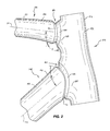
- FIG. 5 is an enlarged view of one of the joints shown in FIG. 2 .
- FIG. 6 is the section view of FIG. 4 after the tubes are welded together.
- FIG. 7 is an exploded perspective view of a portion of a bicycle frame of a second embodiment of the present invention.
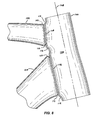
- FIG. 8 is a section view of the frame illustrated in FIG. 7 .
- FIG. 1 illustrates a bicycle 10 that includes a front wheel 12 , a rear wheel 14 , a frame 16 , and a steering assembly 18 .
- the frame 16 includes a top tube 20 , a head tube 22 , a down tube 24 , a seat tube 26 , seatstays 28 , chainstays 30 , and a bottom bracket 32 .
- Pedals 34 are attached to a crankset 36 to allow a user to rotate the crankset 36 and to propel the bicycle 10 , as is known in the art.
- FIG. 2 is an enlarged side view of the head tube 22 and portions of the top tube 20 and down tube 24 prior to those tubes being secured together.
- Each of the top tube 20 and down tube 24 includes a main portion 40 having a generally smooth outer surface 42 that is generally parallel to a longitudinal axis 44 of the tube.
- the illustrated main portions 40 are generally circular or oval in cross section.
- the present invention is not limited to tubes having circular or oval cross sections, but is applicable to tubes having a variety of cross sections.
- each of the top tube 20 and down tube 24 includes an interface portion in the form of a tapered portion 50 that extends at an angle relative to the main portion 40 of each tube.
- the angle of the tapered portion 50 varies depending on the position around the perimeter of the tube. In this illustrated embodiment, the angle ⁇ of the tapered portion 50 of the top tube 20 relative to the longitudinal axis 44 of the top tube 20 varies from about 27 degrees to about 51 degrees.
- the angle ⁇ of the tapered portion 50 of the down tube 24 relative to the longitudinal axis 44 of the down tube 24 varies from about 8 degrees to about 66 degrees.
- the head tube 22 comprises a main portion 52 having an outer surface 54 that generally mimics a cylindrical and/or slightly frustoconical configuration.
- the head tube 22 further includes an upper fillet surface 60 that is designed to provide a smooth transition from the outer surface 54 of the head tube 22 to the outer surface 42 of the main portion 40 of the top tube 20 .
- the head tube 22 also includes a lower fillet surface 62 that is designed to provide a smooth transition from the outer surface 54 of the head tube 22 to the outer surface 42 of the main portion 40 of the down tube 24 .
- the upper and lower fillet surfaces 60 , 62 are designed to mimic a weld fillet that would appear if substantially straight tubes were welded together (e.g., using a mitered joint) and sanded to provide a smooth, radiused transition between the head tube 22 and the top and down tubes 24 , respectively, thus giving the appearance of a molded frame 16 .
- the head tube 22 further includes an upper tapered portion 64 extending at an angle from the upper fillet surface 60 , and a lower tapered portion 66 extending at an angle from the lower fillet surface 62 .
- the upper and lower tapered portions 64 , 66 are designed to fit with the tapered portions 50 of the top tube 20 and down tube 24 , respectively, to form pre-weld joints.
- the angle of the upper and lower tapered portions 64 , 66 varies around the perimeter of the upper and lower fillet surfaces 60 , 62 . In the illustrated embodiment, the angle of the upper tapered portion 64 is about 36 degrees to about 91 degrees relative to the longitudinal axis 44 of the top tube 20 .
- the angle of the lower tapered 66 portion varies from about 30 degrees to about 59 degrees relative to the longitudinal axis 44 of the down tube 24 .
- the end of the tapered portion 50 of the top tube 20 fits inside the end of the upper tapered portion 64 of the head tube 22 .
- an outer surface 70 of the tapered portion 50 of the top tube 20 engages an inner edge 72 or surface of the upper tapered portion 64 .
- an inner dimension 74 of the tapered portion 50 of the top tube 20 is smaller than a corresponding inner dimension 76 of the upper tapered portion 64 .
- the end of the tapered portion 50 of the down tube 24 fits within the end of the lower tapered portion 66 of the head tube 22 .
- top tube 20 , down tube 24 , and head tube 22 results in creation of a peripheral channel 80 around the joint between the top tube 20 and head tube 22 and the joint between the down tube 24 and head tube 22 .
- These channels 80 are dimensioned such that the cross-sectional area of each channel (i.e., the triangular region defined by the tapered portions) does not vary substantially around the perimeter of the joint. The result is a substantially uniform cross-section weld joint that is easier to weld. With skilled welders, it is believed that welding of these joints can result in a near finished products, with the weld bead substantially flush with the adjacent surfaces, thus requiring little or no grinding, filing, or sanding.
- the illustrated peripheral channels 80 are substantially V-shaped, and an angle ⁇ at the base of the channel varies between about 80 degrees and about 96 degrees.
- the channels have a depth 82 that is greater than the wall thickness 84 of the tubes being welded.
- the depth 82 ( FIG. 5 ) of the channel between the top tube 20 and head tube 22 is about 5 millimeters
- a wall thicknesses 84 of the top tube and head tube at the joint are about 2 mm and 2.5 mm, respectively.
- the ratio between the channel depth and the tube wall thickness is about 2.5:1 for the top tube and about 2:1 for the head tube.
- channels do not need to have straight sidewalls, but instead could have curved sidewalls, such as when the tube ends are domed.
- FIG. 5 illustrates an enlarged view of one of the V-shaped channels 80 created by the above-described tapered portions 50 , 64 .
- This enlarged view shows that the illustrated tapered portions 50 , 64 do not extend directly from the ends of the outer surfaces 42 , 60 of the tubes. Rather, each tapered portion 50 , 64 is offset such that there is a shoulder 86 between the outer surfaces 42 , 60 and the tapered portions 50 , 64 .
- the illustrated shoulder 86 is radiused, but could instead be straight.
- the illustrated shoulder has a shoulder depth 88 of about 0.5 mm, thus creating shoulder depth 88 to wall thickness ratio of about 1:3.
- FIG. 6 illustrates weld beads 92 (in broken lines) after the joints are welded.
- the weld beads 92 are substantially flush, or might protrude slightly outward from the joint beyond the outer surfaces of the tubes.
- the weld 92 can then be finished (e.g., ground, filed, sanded, etc.), if necessary, until it is flush with the outer surfaces of the tubes.
- the result is a welded bicycle frame that, once painted, will look like a single-piece molded bicycle frame.
- FIGS. 7 and 8 illustrate a second embodiment of the present invention including a head tube 100 , a top tube 102 , and a down tube 104 .
- the head tube 100 has a main portion 106 that defines a longitudinal axis 108 .
- the second embodiment is similar to the embodiment of FIGS. 2-6 in that, inter alia, wall thicknesses of the top tube 102 and down tube 104 are less than the wall thickness of the head tube 100 , and the tapered portions of the tubes define a channel that is deeper than the wall thicknesses of the tubes.
- the embodiments differ in that, inter alia, the tapered portions 110 of the first tubular members of the second embodiment are more rounded, and the tapered portion 110 of the second embodiment are not offset by the previously-described shoulder 86 and shoulder depth 88 .
- fillet surfaces 112 of the head tube 100 of the second embodiment transition to substantially flat, upper and lower face walls 114 , 116 , the outer perimeter of which at least partially define the tapered portion 110 that acts as a weld interface between the head tube 100 and the corresponding top tube 102 or down tube 104 .
- the upper and lower face walls 114 , 116 are substantially parallel (i.e., +/ ⁇ 15 degrees) to the longitudinal axis 108 of the head tube 100 .
- the upper face wall 114 is positioned at an angle of about 9 degrees relative to the longitudinal axis 108
- the lower face wall 116 is positioned and an angle of about zero degrees relative to the longitudinal axis 108 .
- the illustrated face falls 114 , 116 are substantially solid or closed and do not have an opening extending into the interior of the head tube 100 .
- the flat face walls 114 , 116 can have openings 118 (shown in broken lines in FIG. 7 ) that provide communication between the interior of the top tube 102 and/or down tube 104 and the interior of the head tube 100 .
Abstract
A bicycle frame comprising a first tubular member having a first main portion and a first interface portion (e.g., a rounded taper), and a second tubular member having a second main portion and a second interface portion engaged with the first interface portion to create a joint. The joint includes a peripheral channel defined between the first interface portion and the second interface portion, and a weld is positioned in the peripheral channel. The second interface portion is defined at least partially by a substantially flat face wall. Preferably, the first tubular member includes an open end at the first interface portion, while the flat face wall at the second interface portion is substantially closed. In addition, it is preferred that the face wall lies in a plane that is substantially parallel to a longitudinal axis of the head tube (e.g., within ten degrees of the longitudinal axis).
Description
The present invention relates to bicycle frames, and particularly to weld joints of tubular bicycle frames.
Bicycle frames are commonly manufactured from tubes that are coupled together into a desired configuration. When the tubes are metal (e.g., steel, aluminum, titanium, etc.), they can be welded together to form the bicycle frame. When manufacturing a welded bicycle frame, the ends of the tubes are pre-cut so that the tubes fit together to form pre-weld joints between the tubes. For example, one tube can be mitered so that it wraps snugly around the tube to which it will be welded. When tubes of similar size are coupled using a mitered joint, the geometry of the joint varies dramatically around the tube interface, from essentially a T-joint at the top and bottom to essentially a tangent joint on the sides, with the mitered tube having a razor thin wall thickness at the tangent joint.
When welding tubes having mitered joints, a weld fillet is formed around the joint. Due to the varying joint geometry of the above-described mitered joint, creating a good, consistent weld is very difficult. At the location where the tubes are tangent, the weld bead commonly protrudes substantially above the surfaces of the tubes being welded. If a smooth joint is desired, one would need to grind or sand the weld bead.
The present invention relates to an improved weld joint structure between two parts. This improved joint structure is designed to make the weld bead more flush with the outer surfaces of the parts being welded to give the appearance of a smooth transition between the outer surfaces of the parts, and to reduce or eliminate post-weld finishing operations, such as grinding or sanding.
The invention provides a bicycle frame comprising a first tubular member having a first main portion and a first interface portion (e.g., a rounded taper), and a second tubular member having a second main portion and a second interface portion engaged with the first interface portion to create a joint. The joint includes a peripheral channel defined between the first interface portion and the second interface portion, and a weld is positioned in the peripheral channel. The second interface portion is defined at least partially by a substantially flat face wall.
In one embodiment, the channel has a channel depth that is greater than a wall thickness of the first tubular member. For example, a ratio of the channel depth to the wall thickness can be at least 1.5:1, and is preferably at least 2:1.
Preferably, the first tubular member includes an open end at the first interface portion, while the flat face wall at the second interface portion is substantially closed. In addition, it is preferred that the face wall lies in a plane that is substantially parallel to a longitudinal axis of the head tube (e.g., within ten degrees of the longitudinal axis).
It is anticipated that some aspects of this invention are applicable to bicycle components other than frames. Other aspects of the invention will become apparent by consideration of the detailed description and accompanying drawings.
Before any embodiments of the invention are explained in detail, it is to be understood that the invention is not limited in its application to the details of construction and the arrangement of components set forth in the following description or illustrated in the following drawings. The invention is capable of other embodiments and of being practiced or of being carried out in various ways.
The end of each of the top tube 20 and down tube 24 includes an interface portion in the form of a tapered portion 50 that extends at an angle relative to the main portion 40 of each tube. The angle of the tapered portion 50 varies depending on the position around the perimeter of the tube. In this illustrated embodiment, the angle α of the tapered portion 50 of the top tube 20 relative to the longitudinal axis 44 of the top tube 20 varies from about 27 degrees to about 51 degrees. The angle β of the tapered portion 50 of the down tube 24 relative to the longitudinal axis 44 of the down tube 24 varies from about 8 degrees to about 66 degrees.
With continued reference to FIG. 2 , the head tube 22 comprises a main portion 52 having an outer surface 54 that generally mimics a cylindrical and/or slightly frustoconical configuration. The head tube 22 further includes an upper fillet surface 60 that is designed to provide a smooth transition from the outer surface 54 of the head tube 22 to the outer surface 42 of the main portion 40 of the top tube 20. The head tube 22 also includes a lower fillet surface 62 that is designed to provide a smooth transition from the outer surface 54 of the head tube 22 to the outer surface 42 of the main portion 40 of the down tube 24. More specifically, the upper and lower fillet surfaces 60, 62 are designed to mimic a weld fillet that would appear if substantially straight tubes were welded together (e.g., using a mitered joint) and sanded to provide a smooth, radiused transition between the head tube 22 and the top and down tubes 24, respectively, thus giving the appearance of a molded frame 16.
The head tube 22 further includes an upper tapered portion 64 extending at an angle from the upper fillet surface 60, and a lower tapered portion 66 extending at an angle from the lower fillet surface 62. The upper and lower tapered portions 64, 66 are designed to fit with the tapered portions 50 of the top tube 20 and down tube 24, respectively, to form pre-weld joints. The angle of the upper and lower tapered portions 64, 66 varies around the perimeter of the upper and lower fillet surfaces 60,62. In the illustrated embodiment, the angle of the upper tapered portion 64 is about 36 degrees to about 91 degrees relative to the longitudinal axis 44 of the top tube 20. The angle of the lower tapered 66 portion varies from about 30 degrees to about 59 degrees relative to the longitudinal axis 44 of the down tube 24.
Referring to FIG. 4 , the end of the tapered portion 50 of the top tube 20 fits inside the end of the upper tapered portion 64 of the head tube 22. In other words, an outer surface 70 of the tapered portion 50 of the top tube 20 engages an inner edge 72 or surface of the upper tapered portion 64. In this regard, it can be seen that an inner dimension 74 of the tapered portion 50 of the top tube 20 is smaller than a corresponding inner dimension 76 of the upper tapered portion 64. Similarly, the end of the tapered portion 50 of the down tube 24 fits within the end of the lower tapered portion 66 of the head tube 22. This configuration provides for a relatively secure dry fit between the tubes prior to the welding operation, which facilitates the proper alignment and positioning of the tubes relative to each other. The above-described arrangement could be reversed, with one or both of the upper and lower tapered portions 64, 66 fitting inside the corresponding tapered portion 50 of the top tube 20 and down tube 24, respectively. However, it is considered desirable to have the thinner tube (i.e., the top tube and down tube in the illustrated embodiment) positioned inside the thicker tube (i.e., the head tube in the illustrated embodiment).
With further reference to FIGS. 2 and 4 , the above-described configuration of top tube 20, down tube 24, and head tube 22 results in creation of a peripheral channel 80 around the joint between the top tube 20 and head tube 22 and the joint between the down tube 24 and head tube 22. These channels 80 are dimensioned such that the cross-sectional area of each channel (i.e., the triangular region defined by the tapered portions) does not vary substantially around the perimeter of the joint. The result is a substantially uniform cross-section weld joint that is easier to weld. With skilled welders, it is believed that welding of these joints can result in a near finished products, with the weld bead substantially flush with the adjacent surfaces, thus requiring little or no grinding, filing, or sanding.
The illustrated peripheral channels 80 are substantially V-shaped, and an angle γ at the base of the channel varies between about 80 degrees and about 96 degrees. In the illustrated embodiment, the channels have a depth 82 that is greater than the wall thickness 84 of the tubes being welded. For example, the depth 82 (FIG. 5 ) of the channel between the top tube 20 and head tube 22 is about 5 millimeters, and a wall thicknesses 84 of the top tube and head tube at the joint (i.e., the interface portions) are about 2 mm and 2.5 mm, respectively. In this configuration, the ratio between the channel depth and the tube wall thickness is about 2.5:1 for the top tube and about 2:1 for the head tube.
It should be understood that the channels do not need to have straight sidewalls, but instead could have curved sidewalls, such as when the tube ends are domed.
In the illustrated embodiment, the upper and lower face walls 114,116 are substantially parallel (i.e., +/−15 degrees) to the longitudinal axis 108 of the head tube 100. Specifically, the upper face wall 114 is positioned at an angle of about 9 degrees relative to the longitudinal axis 108, and the lower face wall 116 is positioned and an angle of about zero degrees relative to the longitudinal axis 108. In addition, the illustrated face falls 114,116 are substantially solid or closed and do not have an opening extending into the interior of the head tube 100. In an alternative embodiment, the flat face walls 114,116 can have openings 118 (shown in broken lines in FIG. 7 ) that provide communication between the interior of the top tube 102 and/or down tube 104 and the interior of the head tube 100.
Various features and advantages of the invention are set forth in the following claims.
Claims (10)
1. A bicycle frame comprising:
a first tubular member having a first main portion and a first interface portion;
a second tubular member having a second main portion and a second interface portion engaged with the first interface portion to create a joint, wherein the joint includes a peripheral channel defined between the first interface portion and the second interface portion, and wherein the second interface portion is defined at least partially by a substantially flat face wall; and
a weld positioned in the peripheral channel.
2. A bicycle frame as claimed in claim 1 , wherein the first interface portion comprises a rounded tapered portion.
3. A bicycle frame as claimed in claim 1 , wherein the channel has a channel depth that is greater than a wall thickness of the first tubular member.
4. A bicycle frame as claimed in claim 1 , wherein the first tubular member has a wall thickness, and where a ratio of the channel depth to the wall thickness is at least 1.5:1.
5. A bicycle frame as claimed in claim 4 , wherein the ratio is at least 2:1.
6. A bicycle frame as claimed in claim 1 , wherein the wall thickness of the first interface portion is thinner than a wall thickness of the second interface portion.
7. A bicycle frame as claimed in claim 1 , wherein the first tubular member includes an open end at the first interface portion, and wherein the flat face wall at the second interface portion is substantially closed.
8. A bicycle frame as claimed in claim 1 , wherein the first tubular member further includes a fillet surface between the second main portion and the second interface portion.
9. A bicycle frame as claimed in claim 1 , wherein the face wall lies in a plane that is substantially parallel to a longitudinal axis of the head tube.
10. A bicycle frame as claimed in claim 9 , wherein the plane is within ten degrees of the longitudinal axis.
Priority Applications (2)
| Application Number | Priority Date | Filing Date | Title |
|---|---|---|---|
| US13/281,210 US8579316B2 (en) | 2009-08-26 | 2011-10-25 | Bicycle frame with improved weld joint |
| DE201210219272 DE102012219272A1 (en) | 2011-10-25 | 2012-10-23 | Bicycle frame includes a weld positioned in the peripheral channel forming part of the joint and which is defined between the interfaces of the tubes |
Applications Claiming Priority (2)
| Application Number | Priority Date | Filing Date | Title |
|---|---|---|---|
| US12/548,214 US8042822B2 (en) | 2009-08-26 | 2009-08-26 | Bicycle frame with improved weld joint |
| US13/281,210 US8579316B2 (en) | 2009-08-26 | 2011-10-25 | Bicycle frame with improved weld joint |
Related Parent Applications (1)
| Application Number | Title | Priority Date | Filing Date |
|---|---|---|---|
| US12/548,214 Continuation-In-Part US8042822B2 (en) | 2009-08-26 | 2009-08-26 | Bicycle frame with improved weld joint |
Publications (2)
| Publication Number | Publication Date |
|---|---|
| US20120038129A1 US20120038129A1 (en) | 2012-02-16 |
| US8579316B2 true US8579316B2 (en) | 2013-11-12 |
Family
ID=45564268
Family Applications (1)
| Application Number | Title | Priority Date | Filing Date |
|---|---|---|---|
| US13/281,210 Active 2030-05-29 US8579316B2 (en) | 2009-08-26 | 2011-10-25 | Bicycle frame with improved weld joint |
Country Status (1)
| Country | Link |
|---|---|
| US (1) | US8579316B2 (en) |
Cited By (1)
| Publication number | Priority date | Publication date | Assignee | Title |
|---|---|---|---|---|
| US10184522B2 (en) | 2015-01-30 | 2019-01-22 | Specialized Bicycle Components, Inc. | Bottom bracket assembly and bicycle |
Families Citing this family (4)
| Publication number | Priority date | Publication date | Assignee | Title |
|---|---|---|---|---|
| JP6152670B2 (en) * | 2013-03-14 | 2017-06-28 | スズキ株式会社 | Frame structure of saddle riding type vehicle |
| KR101875647B1 (en) | 2016-10-31 | 2018-07-06 | 현대자동차 주식회사 | Bycycle frame structure including rear frame and front frame |
| KR102371244B1 (en) * | 2017-06-01 | 2022-03-04 | 현대자동차 주식회사 | Bicycle frame and manufacturing method of the same |
| CN112404888A (en) * | 2020-09-23 | 2021-02-26 | 浙江德利福科技股份有限公司 | Forming process of stainless steel three-way pipe |
Citations (14)
| Publication number | Priority date | Publication date | Assignee | Title |
|---|---|---|---|---|
| FR757201A (en) | 1933-02-15 | 1933-12-22 | Racks, frames, and accessories therefor for bicycles, motorcycles and the like | |
| US2453061A (en) | 1943-05-27 | 1948-11-02 | W K Mitchell & Company Inc | Electric resistance and filler metal butt welding |
| US4583755A (en) | 1984-12-04 | 1986-04-22 | Huffy Corporation | Bicycle frame |
| US4813591A (en) | 1988-04-04 | 1989-03-21 | Schwinn Bicycle Company | Method of fabricating a rear fork assembly for a bicycle and drop out bracket therefor |
| US5056704A (en) | 1988-02-22 | 1991-10-15 | Tube Forming, Inc. | Tube fitting having a saddle bead with conforming pilot |
| US5363715A (en) | 1993-06-28 | 1994-11-15 | Eaton Corporation | Transmission X-control mechanism and pivot pin therefore |
| US6123353A (en) | 1997-02-19 | 2000-09-26 | Techmatics, Inc. | Method of joining and reinforcing molded plastic bicycle frames |
| US6365865B1 (en) | 1999-03-26 | 2002-04-02 | Chuohatsujo Kabushiki Kaisha | Process for welding fixture pipes to opposite ends of hollow stabilizer's suspension arm for vehicle |
| US6375210B1 (en) | 1999-05-11 | 2002-04-23 | Rocky Mountain Bicycles, A Division Of Procycle Group Inc. | Head tube junction on a bicycle |
| US6481522B1 (en) | 1999-06-29 | 2002-11-19 | Honda Giken Kogyo Kabushiki Kaisha | Frame structure for motorcycle |
| US6874676B1 (en) | 2001-05-04 | 2005-04-05 | Creare Inc. | Method and structure for welding an air-sensitive metal in air |
| US6889992B2 (en) | 2000-09-20 | 2005-05-10 | Cervelo Cycles, Inc. | Aerodynamic bicycle frame |
| US20080100029A1 (en) | 2006-10-26 | 2008-05-01 | Astro Engineering Co., Ltd. | One-piece frame for a bicycle |
| US20100320721A1 (en) | 2009-06-17 | 2010-12-23 | Ching-Chi Chung | Tube seat with a frame structure for a bicycle |
-
2011
- 2011-10-25 US US13/281,210 patent/US8579316B2/en active Active
Patent Citations (14)
| Publication number | Priority date | Publication date | Assignee | Title |
|---|---|---|---|---|
| FR757201A (en) | 1933-02-15 | 1933-12-22 | Racks, frames, and accessories therefor for bicycles, motorcycles and the like | |
| US2453061A (en) | 1943-05-27 | 1948-11-02 | W K Mitchell & Company Inc | Electric resistance and filler metal butt welding |
| US4583755A (en) | 1984-12-04 | 1986-04-22 | Huffy Corporation | Bicycle frame |
| US5056704A (en) | 1988-02-22 | 1991-10-15 | Tube Forming, Inc. | Tube fitting having a saddle bead with conforming pilot |
| US4813591A (en) | 1988-04-04 | 1989-03-21 | Schwinn Bicycle Company | Method of fabricating a rear fork assembly for a bicycle and drop out bracket therefor |
| US5363715A (en) | 1993-06-28 | 1994-11-15 | Eaton Corporation | Transmission X-control mechanism and pivot pin therefore |
| US6123353A (en) | 1997-02-19 | 2000-09-26 | Techmatics, Inc. | Method of joining and reinforcing molded plastic bicycle frames |
| US6365865B1 (en) | 1999-03-26 | 2002-04-02 | Chuohatsujo Kabushiki Kaisha | Process for welding fixture pipes to opposite ends of hollow stabilizer's suspension arm for vehicle |
| US6375210B1 (en) | 1999-05-11 | 2002-04-23 | Rocky Mountain Bicycles, A Division Of Procycle Group Inc. | Head tube junction on a bicycle |
| US6481522B1 (en) | 1999-06-29 | 2002-11-19 | Honda Giken Kogyo Kabushiki Kaisha | Frame structure for motorcycle |
| US6889992B2 (en) | 2000-09-20 | 2005-05-10 | Cervelo Cycles, Inc. | Aerodynamic bicycle frame |
| US6874676B1 (en) | 2001-05-04 | 2005-04-05 | Creare Inc. | Method and structure for welding an air-sensitive metal in air |
| US20080100029A1 (en) | 2006-10-26 | 2008-05-01 | Astro Engineering Co., Ltd. | One-piece frame for a bicycle |
| US20100320721A1 (en) | 2009-06-17 | 2010-12-23 | Ching-Chi Chung | Tube seat with a frame structure for a bicycle |
Cited By (1)
| Publication number | Priority date | Publication date | Assignee | Title |
|---|---|---|---|---|
| US10184522B2 (en) | 2015-01-30 | 2019-01-22 | Specialized Bicycle Components, Inc. | Bottom bracket assembly and bicycle |
Also Published As
| Publication number | Publication date |
|---|---|
| US20120038129A1 (en) | 2012-02-16 |
Similar Documents
| Publication | Publication Date | Title |
|---|---|---|
| US8042822B2 (en) | Bicycle frame with improved weld joint | |
| US8579316B2 (en) | Bicycle frame with improved weld joint | |
| US7971892B2 (en) | Bicycle frame construction | |
| US20070145704A1 (en) | Vehicle suspension beam | |
| US8167327B2 (en) | Bicycle frame | |
| WO2011118618A1 (en) | Structure for side section of vehicle body | |
| JPS598590B2 (en) | motorcycle frame | |
| US9440701B2 (en) | Body frame for bicycle | |
| US8684388B1 (en) | Head tube weld joint | |
| JP2003334680A (en) | Welding method and connected structural body using the same | |
| US9108696B2 (en) | Frame unit for bicycle and method of manufacturing the same | |
| WO2012168611A1 (en) | Motor vehicle body shell lower side member and vehicle equipped with such side members | |
| JP6208605B2 (en) | Motorcycle fuel tank | |
| JP3929816B2 (en) | Hairline processing method | |
| US10184522B2 (en) | Bottom bracket assembly and bicycle | |
| DE102012219272A1 (en) | Bicycle frame includes a weld positioned in the peripheral channel forming part of the joint and which is defined between the interfaces of the tubes | |
| JPH0238865Y2 (en) | ||
| JPS6226178A (en) | Steering head for motorcycle | |
| CN209565652U (en) | Integral hollow pipe part | |
| JP4698199B2 (en) | Closed section welded structure and manufacturing method thereof | |
| JP2542818B2 (en) | Motorcycle body frame structure | |
| JPS6318558B2 (en) | ||
| JP6319891B2 (en) | Manufacturing method of wing body and rear department structure | |
| JP2006110165A (en) | Structure of handle part of manual cutlery | |
| US20150344095A1 (en) | Body frame for bicycle |
Legal Events
| Date | Code | Title | Description |
|---|---|---|---|
| AS | Assignment |
Owner name: SPECIALIZED BICYCLE COMPONENTS, INC., CALIFORNIA Free format text: ASSIGNMENT OF ASSIGNORS INTEREST;ASSIGNORS:D'ALUISIO, CHRISTOPHER P.;FRASCA, ANDREW;REEL/FRAME:027118/0804 Effective date: 20111025 |
|
| STCF | Information on status: patent grant |
Free format text: PATENTED CASE |
|
| FPAY | Fee payment |
Year of fee payment: 4 |
|
| MAFP | Maintenance fee payment |
Free format text: PAYMENT OF MAINTENANCE FEE, 8TH YEAR, LARGE ENTITY (ORIGINAL EVENT CODE: M1552); ENTITY STATUS OF PATENT OWNER: LARGE ENTITY Year of fee payment: 8 |