US8577172B2 - Reconfigurable module and method of implementing this reconfigurable module for performing morphological operations - Google Patents
Reconfigurable module and method of implementing this reconfigurable module for performing morphological operations Download PDFInfo
- Publication number
- US8577172B2 US8577172B2 US13/062,282 US200913062282A US8577172B2 US 8577172 B2 US8577172 B2 US 8577172B2 US 200913062282 A US200913062282 A US 200913062282A US 8577172 B2 US8577172 B2 US 8577172B2
- Authority
- US
- United States
- Prior art keywords
- input
- output
- logic block
- block
- image
- Prior art date
- Legal status (The legal status is an assumption and is not a legal conclusion. Google has not performed a legal analysis and makes no representation as to the accuracy of the status listed.)
- Expired - Fee Related, expires
Links
Images


Classifications
-
- H—ELECTRICITY
- H03—ELECTRONIC CIRCUITRY
- H03K—PULSE TECHNIQUE
- H03K19/00—Logic circuits, i.e. having at least two inputs acting on one output; Inverting circuits
- H03K19/0175—Coupling arrangements; Interface arrangements
Definitions
- the invention relates to a reconfigurable module and a method of implementing this reconfigurable module for performing morphological operations.
- it provides a single reconfigurable module that allows a set of morphological operations applied to image processing to be carried out.
- the reconfigurable module notably allows an integral image, an eroded image, an expanded image, a Manhattan distance image and projections of the original image to be determined.
- the invention is notably applicable to the fields of onboard electronics such as video for mobile telephony or computer-aided driving systems.
- Morphological operations form the basic operations for image processing. For this reason, they are much used in image processing. With the development of multimedia technologies, in particular the enhancement of the image resolutions associated with the miniaturization of electronic circuits, there is now a growing need for optimization of these morphological operations.
- ASICs application specific integrated circuits
- an ASIC circuit on its own, only allows one particular morphological operation to be accelerated. In other words, no ASIC module exists that is actually capable of accelerating several morphological operations.
- a particular ASIC circuit is only able to perform these operations for a structural element of predefined dimensions, or, at the very least, for structural elements with dimensions smaller than the predefined dimensions.
- an ASIC circuit performing an erosion or expansion operation for a structural element of dimensions 3 ⁇ 3 cannot carry out this erosion or expansion operation for a structural element of dimensions 5 ⁇ 5.
- One solution to these two limitations thus consists in using a programmable processing structure such as a personal computer.
- a structure exhibits a performance that is greatly inferior to that of ASIC circuits.
- at least three cycles per pixel are required in order to obtain a result with a programmable structure, whereas a result can be obtained for several pixels in a single cycle with certain ASIC circuits.
- One aim of the invention is notably to overcome all or a part of the aforementioned drawbacks by providing a reconfigurable module allowing several morphological operations to be performed with the best compromise with respect to performance-flexibility-silicon surface area.
- one subject of the invention is a reconfigurable module comprising an operational block with five inputs and three outputs.
- the first output of the operational block is capable of delivering either the result of the addition of the first and second inputs of the operational block, or the result of the subtraction of the second input from the first input of the operational block, or the minimum of the first and second inputs of the operational block, or the maximum of the first and second inputs of the operational block.
- the second output of the operational block is capable of delivering either the result of the addition of the fourth and fifth inputs of the operational block, or the result of the subtraction of the fifth input from the fourth input of the operational block, or the minimum of the fourth and fifth inputs of the operational block, or the maximum of the fourth and fifth inputs of the operational block, or the minimum of the first, second and fourth inputs of the operational block, or the maximum of the first, second and fourth inputs of the operational block.
- the third output of the operational block is capable of delivering either the result of the addition of the first output and the third input of the operational block, or the result of the subtraction of the third input from the first output of the operational block.
- the invention notably has the advantage of allowing the operations for integration, erosion, expansion, Manhattan distance and projection to be carried out with a single module and in an optimized manner.
- the erosion and expansion operations can furthermore be carried out with structural elements of dimensions greater than 3 ⁇ 3 by serially combining the reconfigurable modules.
- the method comprises a step consisting in determining, starting from an original image comprising M rows and N columns of pixels p(m,n), M and N being positive integers, either an integral image, an eroded image, an expanded image, a Manhattan distance image, or a projection along the rows and a projection along the columns of the original image.
- the type of final image can be determined depending on the type of operations carried out by adders/subtracters belonging to the operational block and links established between inputs and outputs of logic blocks belonging to the operational block.
- the integral image, the eroded image, the expanded image and the Manhattan distance image have the same dimensions as the original image.
- FIG. 1 a an example of an original image
- FIG. 1 b an integral image associated with the original image in FIG. 1 a;
- FIG. 2 an illustration of the principle for calculation of the weights of a set of pixels using an integral image
- FIG. 3 a a second example of an original image
- FIG. 3 b an intermediate image obtained by a first step of the integral image operation according to the invention starting from the original image in FIG. 3 a;
- FIG. 3 c an integral image obtained by a second step of the integral image operation according to the invention starting from the intermediate image in FIG. 3 b;
- FIG. 4 an illustration of the principle of determination of an eroded image and of an expanded image starting from a third example of an original image
- FIG. 5 an illustration of the decomposition of a structural element into two sub-elements
- FIG. 6 a an illustration of the principle for determination of an intermediate image obtained by a first step of the erosion operation according to the invention starting from a fourth example of an original image;
- FIG. 6 b an illustration of the principle of determination of an eroded image obtained by a second step of the erosion operation according to the invention starting from the intermediate image in FIG. 6 a;
- FIG. 7 a fifth example of a binary original image and of a distance image associated with it
- FIG. 8 an illustration of the principle for determination of the distance image starting from the binary original image in FIG. 7 ;
- FIG. 9 sub-steps of the city-block distance operation according to the invention allowing an intermediate image to be obtained starting from a binary original image
- FIG. 10 an example of a binary original image and an intermediate image obtained starting from the sub-steps in FIG. 9 ;
- FIG. 11 sub-steps of the city-block distance operation according to the invention allowing a distance image to be obtained starting from an intermediate image
- FIG. 12 the intermediate image in FIG. 10 and a distance image obtained starting from the sub-steps in FIG. 11 ;
- FIG. 13 an illustration of the projection operation
- FIG. 14 an example of operational block
- FIG. 15 a reconfigurable module comprising the operational block in FIG. 14 ;
- FIG. 16 an example of serial combination of two reconfigurable modules according to FIG. 15 .
- matrix images will be employed, in other words images composed of pixels laid out in rows and columns. From a geometrical point of view, the pixels are equivalent to rectangles of similar size.
- a pixel p(m,n) is located with reference to a point of origin O using its position in a row m and in a column n, m and n being integers in the range between 1 and, respectively, the number M of rows and the number N of columns in the image.
- rectangular images are considered, in other words images comprising the same number of pixels p(m,n) for each row.
- FIGS. 1 a and 1 b illustrate the principle of a first morphological operation, referred to as integration.
- a scalar value known as weighting wo(m,n) is associated with each pixel p(m,n) of the original image.
- the weighting wo(m,n) can thus be in the range between the values 0 and 255.
- the integral image operation consists in determining an image referred to as integral image, of same size as the original image, for which the weighting wi(m,n) of each pixel p(m,n) is determined from the sum of the weighting wo(m,n) of all the pixels p(x,y) situated in the rectangular area bounded by the origin O and the pixel p(m,n) in question.
- the integral image operation may be modeled by the equation:
- FIG. 2 illustrates the principle for calculating the weighting of a rectangle ABCD.
- the use of the integral image avoids having to add up all the weightings wo(m,n) of the pixels p(m,n) belonging to the surface ABCD. This is particularly advantageous where several surfaces have to be calculated for the same image and where the resolution of the image is high.
- the integral image is determined in two steps, a first step determining an intermediate image starting from the original image and a second step determining the integral image starting from the intermediate image.
- the intermediate image has, like the integral image, the same size as the original image.
- An example of an original image is shown in FIG. 3 a .
- the weightings wii(m,n) of the pixels p(m,n) for the intermediate image are determined from one to the next by adding to the weighting wo(m,n) of the pixel p(m,n) in question in the original image the weighting wii(m ⁇ 1,n) of the pixel p(m ⁇ 1,n) in the intermediate image situated in the same column on the preceding row.
- the result for the intermediate image is illustrated in FIG.
- the weightings wi(m,n) of the pixels p(m,n) for the integral image are then determined, again from one to the next, by adding to the weighting wii(m,n) of the pixel p(m,n) in question in the intermediate image the weighting wi(m,n ⁇ 1) of the pixel p(m,n ⁇ 1) in the integral image situated on the same row in the preceding column.
- the result of the integral image is illustrated in FIG. 3 c .
- the determination of the weightings wii(m,n) for the intermediate image and of the weightings wi(m,n) for the integral image may be modeled by the following algorithm:
- the equations 3 and 4 of the preceding algorithm are then determined for m varying from 2 to M and for n varying from 2 to N.
- the intermediate image is obtained by adding row by row the weightings wo(m,n) and wii(m ⁇ 1,n) of the pixels p(m,n) and p(m ⁇ 1,n) of the original image and of the intermediate image and that the integral image is obtained by adding column by column the weightings wii(m,n) and wi(m,n ⁇ 1) of the pixels p(m,n) and p(m,n ⁇ 1) of the intermediate image and of the integral image.
- the additions row by row may be inverted with the additions column by column by considering the appropriate initialization row and column. The algorithm then becomes:
- FIG. 4 illustrates the principle of two other morphological operations, referred to as erosion and expansion. These two morphological operations are carried out in a similar manner.
- the erosion operation is notably used to eliminate the gray-level peaks and to “widen the holes”, whereas the expansion operation is used to widen the gray-level peaks and to “fill in the holes”.
- These operations make use of a working window, also referred to as structural element, composed of a mesh of pixels. This mesh may be square, rectangular or hexagonal.
- the erosion operation consists in determining, for each pixel p(m,n) of the original image, a weighting we(m,n) corresponding to the minimum of the weightings wo(x,y) of the pixels p(x,y) belonging to the structural element centered on the pixel p(m,n) in question.
- the expansion operation consists in determining, for each pixel p(m,n) of the original image, a weighting wf(m,n) corresponding to the maximum of the weightings wo(x,y) of the pixels p(x,y) belonging to the structural element centered on the pixel p(m,n) in question.
- the erosion and expansion operations are each determined using two steps, a first step determining an intermediate image starting from the original image and a second step determining the eroded or expanded image starting from the intermediate image.
- the structural element of size P ⁇ Q is decomposed into two sub-elements, a first sub-element of size 1 ⁇ Q and a second sub-element of size P ⁇ 1, as shown in FIG. 5 .
- the intermediate image is then determined by scanning, in other words by going from pixel to pixel, the first sub-element on each row of the original image.
- the eroded or expanded image is, in turn, determined by scanning the second sub-element in each column of the intermediate image.
- the weightings wie(m,n) of the pixels p(m,n) of the intermediate image are determined by considering the minimum of the weightings wo(m,n ⁇ 1), wo(m,n) and wo(m,n+1) of the pixels p(m,n ⁇ 1), p(m,n) and p(m,n+1) of the original image.
- the second step shown in FIG.
- the weightings we(m,n) of the pixels p(m,n) of the eroded image are determined by considering the minimum of the weightings wie(m ⁇ 1,n), wie(m,n) and wie(m+1,n) of the pixels p(m ⁇ 1,n), p(m,n) and p(m+1,n) of the intermediate image.
- the weightings wo(0,n) and wo(M+1,n) of all the pixels p(0,n) and p(M+1,n) of these framing rows are, for example, set to the highest value (in the case of an erosion) that the weighting wo(m,n) of the pixels p(m,n) of the original image can take, for example 255.
- the weightings wie(m,0) and wie(m,N+1) of all the pixels p(m,0) and p(m,n+1) are for example set to the highest value that the weighting wie(m,n) of the pixels p(m,n) of the intermediate image can take, for example 255.
- first and second steps of the erosion operation may be inverted, the intermediate image then being obtained by minima in columns instead of minima on rows.
- the expansion operation can be easily obtained by adapting the erosion operation, notably by replacing the minimum operations by maximum operations.
- the particular cases of the first and last rows and first and last columns can then be handled by setting the value of the weightings in question to the value zero.
- FIGS. 7 and 8 illustrate the principle of the Manhattan distance operation, also known in the literature by the term “city-block” distance.
- This operation allows the distance of an object in the image to be determined with respect to any point of the image.
- a binary original image must be used, in other words an image composed of pixels whose weighting can only take one of two values, a first value corresponding to a high state, for example ‘1’, and a second value corresponding to a low state, for example ‘0’.
- the binary original image may be obtained by thresholding.
- the pixels of the binary original image corresponding to the object have, for example, a weighting set to the high state, the other pixels having a weighting set to the low state.
- the image obtained by the Manhattan distance operation is an image whose weighting wd(m,n) for each pixel p(m,n) is equal to the Manhattan distance between the pixel p(m,n) in question and the pixel p(x,y) closest to the pixel p(m,n) in question belonging to the object.
- FIG. 7 illustrates an example of a binary original image and the corresponding distance image.
- FIG. 8 illustrates the calculation of the weighting wd(2,3) of the pixel p(2,3) of the distance image.
- One of the pixels closest to the pixel p(2,3) belonging to the object is the pixel p(5,4).
- 4.
- any other path between the object and the pixel p(m,n) in question would lead to the same Manhattan distance, and hence to the same weighting wd(m,n).
- the Manhattan distance operation is, like the other morphological operations according to the invention, determined in two steps.
- a first step determines an intermediate image starting from the original image, in this case the binary original image
- a second step determines the distance image starting from the intermediate image.
- a structural element in the form of a reversed ‘L’ FIG. 10 ) rotated by a quarter turn in the trigonometric sense, and composed of three pixels p(m,n ⁇ 1), p(m,n) and p(m ⁇ 1,n), is successively scanned over each row of the original image starting from the pixel p(1,1).
- the weighting wid(m,n) of this same pixel p(m,n) in the intermediate image is set to zero.
- a structural element again in the form of an ‘L’, ( FIG. 12 ) but rotated by a quarter turn in the anti-trigonometric sense, and composed of three pixels p(m+1,n), p(m,n) and p(m,n+1), is successively scanned over each row of the intermediate image starting from the pixel p(M,N).
- the second step it is also verified whether the central pixel p(m,n) belongs to the object.
- the weighting wd(m,n) of this same pixel p(m,n) in the distance image is set to zero.
- the weighting wd(m,n) of the pixel p(m,n) is determined by the equation 9. This particular embodiment allows the second step to be matched to the first.
- FIG. 9 illustrates sub-steps of the first step.
- a first sub-step referred to as initialization step 101
- the reference value Vref is determined so as to be greater than the number Nmax. It corresponds for example to the maximum value of a register. In the case of VGA resolution images, Vref can be set to the value 2048, i.e an 11-bit register. In the case of images with a resolution referred to as “full HD”, in other words comprising a matrix of 1920*1080 pixels, Vref can be set to 4096, i.e a 12-bit register.
- the row index m and the column index n are reset to the value ‘1’.
- a second sub-step 102 it is verified whether the central pixel p(m,n) belongs to the object, for example by verifying that its weighting wo(m,n) in the original image is equal to the value ‘1’. If such is the case, the weighting wid(m,n) of this pixel in the intermediate image is set to zero in a sub-step 103 in order to indicate a distance of zero between this pixel and the object.
- the weighting wid(m,n) of the central pixel p(m,n) of the intermediate image is set, in a sub-step 104 , to the minimum value of the weightings V 1 and B 1 incremented by one unit, in accordance with the equation 8.
- a sub-step 105 it is checked, in a sub-step 105 , whether the structural element has arrived at the end of the row. This condition is for example verified when the column index n is equal to the number N of columns. If this condition is not verified, the column index n is incremented by one unit in a sixth sub-step 106 .
- a new iteration is executed starting from the second sub-step 102 in order to determine the weighting wid(m,n+1) of the next pixel p(m,n+1) in the row.
- the structural element has arrived at the end of the row, it is checked, in a sub-step 107 , whether the structural element has also arrived at the end of the column, in other words whether the central pixel p(m,n) corresponds to the last pixel p(M,N) of the image. If this condition is verified, the first step is terminated in a sub-step 108 , the intermediate image being completely determined.
- the intermediate image thus obtained is illustrated in FIG.
- FIG. 11 illustrates sub-steps of the second step.
- This second step is for example executed following the sub-step 108 .
- the row index m is reset to the value ‘M’ and the column index n is reset to the value ‘N’.
- the weighting wd(m,n) of the central pixel p(m,n) of the distance image is set to the minimum value of the weightings r, B 2 +1 and V 2 +1, in accordance with the equation 9.
- the column index n is decremented by one unit in a sub-step 204 .
- a new iteration is executed starting from the second sub-step 202 in order to determine the weighting wd(m,n ⁇ 1) of the next pixel p(m,n ⁇ 1) in the row.
- the structural element has arrived at the end of the row, it is checked, in a sub-step 205 , whether the structural element has also arrived at the end of the column, in other words whether the central pixel p(m,n) corresponds to the first pixel p(1,1) of the image.
- the second step is terminated in a sub-step 206 , the distance image being completely determined.
- the distance image thus obtained is illustrated in FIG. 12 .
- the row index m is decremented by one unit and the column index n is reset to the value ‘N’ in a sub-step 207 .
- a new iteration is executed starting from the second sub-step 202 .
- FIG. 13 illustrates the projection operation.
- the weightings wp(X,n) and wp(m,Y) of the pixels p(X,n) and p(m,Y) of the new row and of the new column can be modeled by the equations:
- FIG. 14 shows schematically an operational block of a reconfigurable module according to the invention.
- the operational block comprises five inputs, identified by the letters A, B, C, D and E, and three outputs, indentified by S 0 , S 1 and S. These inputs/outputs notably allow the operations defined hereinabove to be carried out. They also allow variants of these operations to be carried out and other additional functions not described here.
- the operational block also comprises three adders/subtracters and four logic blocks whose configuration allows a result of an operation carried out on the inputs A, B, C, D and/or E to be delivered at each output S 0 , S 1 and S, the result depending on the type of operation performed by the adders/subtracters and on the links established between the inputs and the outputs of the various logic blocks.
- the inputs A, B, C, D and E, the outputs S 0 , S 1 and S together with the inputs/outputs of the adders/subtracters and of the logic blocks, are confounded with the data present on these inputs and these outputs.
- Logic block is understood to mean a controlled circuit having one or more inputs and one or more outputs, where each output may be linked with one of the inputs depending on a command applied to the logic block, for example by a general controller or by a logic internal to the logic block.
- the term logic block is to be understood in the wider sense. It goes without saying that a logic block having several inputs and/or outputs can be formed by an assembly of multiplexers and of logic gates each having one or more inputs and one or more outputs.
- the first output S 0 of the operational block can deliver either the result of the addition (A+B) of the first input A and the second input B of the operational block, or the result of the subtraction (A ⁇ B) of the second input B from the first input A of the operational block, or the minimum (min(A, B)) of the first input A and the second input B of the operational block, or the maximum (max(A, B)) of the first input A and the second input B of the operational block.
- the second output S 1 of the operational block can deliver either the result of the addition (D+E) of the fourth input D and the fifth input E of the operational block, or the result of the subtraction (D ⁇ E) of the fifth input E from the fourth input D of the operational block, or the minimum (min(D, E)) of the fourth input D and the fifth input E of the operational block, or the maximum (max(D, E)) of the fourth input D and the fifth input E of the operational block, or the minimum (min(A, B, D)) of the first input A, the second input B and the fourth input D of the operational block, or the maximum (max(A, B, D)) of the first input A, the second input B and the fourth input D of the operational block.
- the third output S of the operational block can deliver either the result of the addition (S 0 +C) of the first output S 0 and the third input C of the operational block, or the result of the subtraction (S 0 ⁇ C) of the third input C from the first output S 0 .
- the various combinations of results at the three outputs S 0 , S 1 and S of the operational block allow the five morphological operations previously described to be performed with a minimum of components presents in the reconfigurable module. Consequently, it is possible to conserve silicon surface area, and hence to reduce the size and the cost of the reconfigurable module. Furthermore, since the reconfigurable module according to the invention corresponds to an architecture known as a pipeline architecture, a result can be supplied at each clock pulse.
- the result can be the weighting of a pixel from an intermediate image or the weighting of a pixel from an integral image, from an eroded image, from an expanded image or from a distance image. The morphological operations can thus be carried out very rapidly.
- the results that can be obtained at the outputs S 0 , S 1 and S of the operational block result for example from the configuration of the adders/subtracters and of the logic blocks described hereinafter.
- the first input A and the second input B of the operational block are respectively connected to a first and to a second input of a first adder/subtracter add 1 and to a first and to a second input of a first logic block mux A/B.
- An output of the first adder/subtracter add 1 is connected to a third input of the first logic block mux A/B.
- An output of this first logic block mux A/B forms the first output S 0 of the operational block.
- the fourth input D of the operational block is connected to a first input of a second adder/subtracter add 2 and to a first input of a second logic block mux D/E.
- the fifth input E of the operational block is connected to a first input of a third logic block mux E/S.
- An output of this third logic block mux E/S is connected to a second input of a second adder/subtracter add 2 and to a second input of the second logic block mux D/E.
- An output of the second adder/subtracter add 2 is connected to a third input of the second logic block mux D/E.
- An output of the second logic block mux D/E forms the second output S 1 of the operational block.
- the third input C of the operational block and the output of the first logic block mux A/B are respectively connected to a first and to a second input of a fourth logic block mux ABC.
- a first and a second output of this fourth logic block mux ABC are respectively connected to a first and to a second input of a third adder/subtracter add 3.
- An output of the third adder/subtracter add 3 is connected to a second input of the third logic block mux E/S and forms the third output S of the operational block.
- the first output S 0 of the operational block delivers the minimum (min(A, B)) or the maximum (max(A, B)) of the first and second inputs A and B of the operational block by carrying out a subtraction (A ⁇ B) of the second input B from the first input A of the operational block and monitoring the sign of the result of the subtraction (A ⁇ B).
- the sign of the result of the subtraction is for example given by the sign bit of the first adder/subtracter add 1.
- the same principle may be applied to the second adder/subtracter add 2 and to the second logic block mux D/E in order to determine the minimum (min(D, E)) or the maximum (max(D, E)) of the fourth and fifth inputs D and E of the operational block.
- the sign of the result of the subtraction (D ⁇ E) of the fifth input E from the fourth input D of the operational block determines the link to be established between the output and the first or the second input of the second logic block mux D/E.
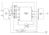
- the reconfigurable module comprises a first input I, a second input I_ch, a first output O, a second output O_ch, a fifth logic block mux I allowing the data stream entering the operational block to be controlled and a sixth logic block mux O allowing the data stream exiting the operational block to be controlled.
- the first input I of the reconfigurable module can be connected to a first input of the fifth logic block mux I and to a first input of the sixth logic block mux O.
- the second input I_ch can be connected to a second input of the fifth logic block mux I.
- a first, a second and a third output of the fifth logic block mux I can respectively be connected to the first, to the second and to the fourth input A, B, D of the operational block.
- the first, second and third outputs S 0 , S 1 , S of the operational block can respectively be connected to a second, to a third and to a fourth input of the sixth logic block mux O.
- An output of the logic block mux O forms the first output O of the reconfigurable module and a fourth output of the logic block mux I forms the second output O_ch of the reconfigurable module.
- This second output O_ch is able to be connected to the input I_ch of a second reconfigurable module in the case of a cascade configuration.
- the reconfigurable module according to the invention can be series combined in order to carry out more complex morphological operations, such as erosion or expansion operations by structural elements of dimensions higher than 3 ⁇ 3.
- the reconfigurable module comprises a FIFO stack allowing data to be temporarily stored and a seventh logic block mux B allowing the data stream entering the second input B of the operational block to be controlled.
- FIFO stack is understood to mean a stack whose first input data bit is the first to be output.
- the second output of the fifth logic block mux I can be connected to a first input of the logic block mux B.
- An output of this logic block mux B can be connected to the second input B of the operational block.
- the first output S 0 of the operational block can be connected to an input of the FIFO stack, and an output of the FIFO stack can be connected to a second input of the seventh logic block mux B and to a fifth input of the sixth logic block mux O.
- the reconfigurable module comprises means for re-injecting the data present on the outputs S 1 and S of the operational block at the input of the operational block.
- these means can comprise an eighth logic block mux A, a ninth logic block mux D and a tenth logic block mux E.
- the first and third outputs of the fifth logic block mux I can respectively be connected to a first input of the eighth logic block mux A and to a first input of the ninth logic block mux D.
- the third output S of the operational block can be connected to a second input of the eighth logic block mux A, to a second input of the ninth logic block mux D and to the third input C of the operational block.
- the second and third outputs S 1 , S of the operational block can respectively be connected to a first and to a second input of the tenth logic block mux E, and an output of this logic block mux E can be connected to the fifth input E of the operational block.
- the reconfigurable module comprises a data register reg C and an eleventh logic block mux C.
- the third output S of the operational block and the data register reg C can respectively be connected to a first and to a second input of the logic block mux C.
- An output of this logic block mux C can be connected to the third input C of the operational block.
- the reconfigurable module described hereinabove can be implemented for carrying out the morphological operations also described hereinabove.
- the reconfigurable module can determine either an integral image, or an eroded image, or an expanded image, or a Manhattan distance image, or a projection along the rows and the columns of the original image, this being carried out depending on the type of operation performed by the adders/subtracters add 1 to add 3 and on the links established between the inputs and the outputs of the various logic blocks.
- the determination of the integral image comprises the following steps:
- the step for addition of the weightings wo(m,n) of the pixels p(m,n) of the original image to the weightings wii(m ⁇ 1,n) of the pixels p(m ⁇ 1,n) of the intermediate image can be carried out in the following manner.
- the weightings wo(m,n) are injected into the first input I of the reconfigurable module;
- the fifth and eighth logic blocks mux I, mux A connect the first input I of the reconfigurable module to the first input A of the operational block;
- the seventh logic block mux B connects the output of the FIFO stack to the second input B of the operational block.
- the operational block can perform the addition of the weightings wo(m,n) and wii(m ⁇ 1,n).
- the sixth logic block mux O connects the output S 0 of the operational block to the output O of the reconfigurable module in order to supply, at this output O and at each clock pulse, a weighting wii(m,n) of a pixel p(m,n) of the intermediate image.
- the step for addition of the weightings wii(m,n) of the pixels p(m,n) of the intermediate image to the weightings wi(m,n ⁇ 1) of the pixels p(m,n ⁇ 1) of the integral image can be carried out in the following manner.
- the weightings wii(m,n) are injected into the first input I of the reconfigurable module; the fifth and eighth logic blocks mux I, mux A connect the first input I of the reconfigurable module to the first input A of the operational block.
- the seventh logic block mux B connects the output of the FIFO stack to the second input B of the operational block.
- the operational block can perform the addition of the weightings wii(m,n) and wi(m,n ⁇ 1), the latter coming from the FIFO stack.
- the sixth logic block mux O connects the output S 0 of the operational block to the output O of the reconfigurable module in order to supply, at this output O and at each clock pulse, a weighting wi(m,n) of a pixel p(m,n) of the integral image.
- the preceding steps, required for the calculation of the integral image, are carried out in the operational block by adding the first input A and the second input B of the operational block using the adder add 1. The result is routed to the output S 0 via the first logic block mux A/B.
- the determination of the eroded image by a structural element of dimension 3 ⁇ 3 comprises the following steps:
- the reconfigurable module by injecting the weighting wo(x,y) or wie(x,y) into the first input I of the reconfigurable module, the fifth logic block mux I successively connecting the first input I of the reconfigurable module to the first input A of the operational block via the eighth logic block mux A, to the second input B of the operational block via the seventh logic block mux B and to the fourth input D of the operational block via the ninth logic block mux D.
- the tenth logic block mux E connects the third output S to the fifth input E of the operational block.
- the operational block can thus determine the minimum of the weightings wo(x,y) or wie(x,y) of the pixels p(x,y) belonging to the first or to the second sub-structural element centered on the pixel p(m,n).
- the sixth logic block mux O connects the second output S 1 of the operational block to the first output O of the reconfigurable module in order to supply, at this output O and at each clock pulse, either the weighting wie(m,n) of the pixels p(m,n) of the intermediate image, or the weighting we(m,n) of the pixels p(m,n) of the eroded image.
- the assignment to the weightings wie(m,n) and we(m,n), respectively, of the minimum of the weightings wo(x,y) of the pixels p(x,y) belonging to the first sub-structural element and of the minimum of the weightings wie(x,y) of the pixels p(x,y) belonging to the second sub-structural element can comprise the following steps:
- the reconfigurable module according to the invention also enables an eroded image or an expanded image to be rapidly determined by a structural element of dimensions higher than 3 ⁇ 3, for example 5 ⁇ 5.
- a comparison of 5 values needs to be made and the minimum of these 5 values retained.
- the idea is to apply the pipeline mode carried out by a reconfigurable module for a 3 ⁇ 3 erosion by using two reconfigurable modules and by distributing the 5 values over the two modules in order to be able to compare them.
- FIG. 16 illustrates an example of an arrangement of two serially combined reconfigurable modules allowing an eroded image to be obtained by a structural element of dimensions 5 ⁇ 5.
- the first output O 1 of a first reconfigurable module 10 is connected to the first input I 2 of a second reconfigurable module 20 and the second output O_ch 1 of the first reconfigurable module 10 is connected to the second output O_ch 2 of the second reconfigurable module 20 .
- the weightings wo(x,y) or wie(x,y) are then injected into the first input I 1 of the first reconfigurable module 10 , the second input I_ch 1 of the first reconfigurable module 10 being unused.
- the minimum of the weightings wo(x,y) of three pixels p(x,y) belonging to the first sub-structural element or the minimum of the weightings wie(x,y) of three pixels belonging to the second sub-structural element can then be obtained at the first output O 1 of the first reconfigurable module 10 , the weightings wo(x,y) or wie(x,y) of the other two pixels p(x,y) belonging to the sub-structural element in question being simply transferred to the second reconfigurable module 20 via the output O_ch 1 and the second input I_ch 2 .
- the minimum of the weightings wo(x,y) or wie(x,y) of the five pixels p(x,y) belonging to the sub-structural element in question can then be obtained at the first output O 2 of the second reconfigurable module 20 .
- the serial combination described hereinabove also allows expanded images to be obtained by a structural element of dimensions 5 ⁇ 5.
- the reconfigurable module according to the invention is particularly well adapted to the serial combination of two or more reconfigurable modules.
- Such a serial combination allows structural elements of greater dimensions to be used.
- a serial combination of three reconfigurable modules allows structural elements of dimensions 7 ⁇ 7 to be used.
- the determination of the distance image comprises the following steps:
- a first structural element composed of three pixels, a central pixel p(m,n), a pixel p(m,n ⁇ 1) situated on the same row as the central pixel p(m,n) in the preceding column and a pixel p(m ⁇ 1,n) situated in the same column as the central pixel p(m,n) on the preceding row,
- a second structural element composed of three pixels, a central pixel p(m,n), a pixel p(m+1,n) situated on the same column as the central pixel p(m,n) on the next row and a pixel p(m,n+1) situated on the same row as the central pixel in the following column,
- the steps for m varying from 1 to M and for n varying from 1 to N can be obtained by the reconfigurable module, notably when the seventh logic block mux B connects the output of the FIFO stack to the second input B of the operational block and the eighth logic block mux A connects the third output S of the operational block to the first input A of the operational block.
- the steps for m varying from M to 1 and for n varying from N to 1 can be obtained by the reconfigurable module, notably when the fifth and ninth logic blocks mux I, mux D connect the first input I of the reconfigurable module to the fourth input D of the operational block, the sixth logic block mux O connects the second output S 1 of the operational block to the first output O of the reconfigurable module, the seventh logic block mux B connects the output of the FIFO stack to the second input B of the operational block and the eighth logic block mux A connects the third output S of the operational block to the first input A of the operational block.
- the assignment to the weighting wid(m,n) of the minimum of the weightings V 1 and B 1 incremented by one unit can comprise the following steps:
- the assignment to the weighting wd(m,n) of the minimum of the weightings r, B 2 +1 and V 2 +1 can comprise the following steps:
- a projection row comprising the same number N of columns as there are rows in the original image and a projection column comprising the same number M of rows as there are columns in the original image, there being respectively associated a weighting wp(X,n) and wp(m,Y) with each pixel p(X,n) of the projection row and with each pixel p(m,Y) of the projection column,
- the step for addition of the weightings wp(m,Y) to the weightings wo(m,n) can be obtained by the reconfigurable module by injecting the weighting wo(m,n) into the first input I of the reconfigurable module.
- the fifth logic block mux I can connect the first input I of the reconfigurable module to the fourth input D of the operational block via the ninth logic block mux D.
- the tenth logic block mux E can connect the second output S 1 to the fifth input E of the operational block.
- the operational block can then calculate the sum of the weightings wo(m,n) of the pixels p(m,n) of a row (m) by means of the second adder/subtracter add 2, the third logic block mux E/S connecting the fifth input E of the operational block to the second input of the second adder/subtracter add 2 and the second logic block mux D/E connecting the output of this adder/subtracter add 2 to the second output S 1 of the operational block.
- the sixth logic block mux O can connect the second output S 1 to the first output O of the reconfigurable module in order to enable the result of the sum of a row (m) to be extracted.
- the step for addition of the weightings wp(X,n) to the weightings wo(m,n) can be obtained by the reconfigurable module by injecting the weighting wo(m,n) into the first input I of the reconfigurable module.
- the fifth logic block mux I can connect the first input I of the reconfigurable module to the first input A of the operational block via the eighth logic block mux A.
- the seventh logic block mux B can connect the output of the FIFO stack to the second input B of the operational block.
- the operational block can then calculate the sum of the weightings wo(m,n) of the pixels p(m,n) of a column (n) by means of the first adder/subtracter add 1, the results of the additions of the weightings wp(X,n) and wo(m,n) being stored in the FIFO stack and the first logic block mux A/B connecting the output of the first adder/subtracter add 1 to the first output S 0 of the operational block.
- the FIFO stack contains the results of the sums of the columns.
- the FIFO stack can then be emptied via the sixth logic block mux O, the latter connecting the output of the FIFO stack to the first output O of the reconfigurable module.
Landscapes
- Engineering & Computer Science (AREA)
- Computer Hardware Design (AREA)
- Physics & Mathematics (AREA)
- Computing Systems (AREA)
- General Engineering & Computer Science (AREA)
- Mathematical Physics (AREA)
- Image Processing (AREA)
- Logic Circuits (AREA)
Abstract
Description
W=A−B+C−D (2)
| FOR m varying from 1 to M, DO: | ||
| FOR n varying from 1 to N, DO: |
| wii(m, n) = wo(m, n)+ wii(m − 1, n) | (3) |
| End FOR |
| End FOR | |
| FOR m varying from 1 to M, DO: |
| FOR n varying from 1 to N, DO: |
| wi(m, n) = wii(m, n)+ wi(m, n − 1) | (4) |
| End FOR |
| End FOR | ||
| FOR n varying from 1 to N, DO: | ||
| FOR m varying from 1 to M, DO: |
| wii(m, n) = wo(m, n)+ wii(m, n − 1) | (3′) |
| End FOR |
| End FOR | |
| FOR n varying from 1 to N, DO: |
| FOR m varying from 1 to M, DO: |
| wi(m, n) = wii(m, n)+ wi(m − 1, n) | (4′) |
| End FOR |
| End FOR | ||
∀(m,n)ε[1,M]×[1,N],
wie(m,n)=min[wo(m,n−1),wo(m,n),wo(m,n+1)] (5)
we(m,n)=min[wie(m−1,n),wie(m,n),wie(m+1,n)] (6)
D=|m−x|+|n−y| (7)
wd(2,3)=D=|2−5|+|3−4|=4.
wid(m,n)=min(V 1+1,B 1+1). (8)
wd(m,n)=min(r,B 2+1,V 2+1). (9)
Nmax=(N−1)+(M−1)
∀nε[1,N],wid(0,n)=Vref−Nmax (10a)
∀mε[1,M],wid(m,0)=Vref−Nmax (10b)
∀nε[1,5],wid(0,n)=FFFF−[(5−1)+(5−1)]=FFF7
∀mε[1,5],wid(m,0)=FFFF−8=FFF7
∀nε[1,N],wd(M+1,n)=Vref−1 (11a)
∀mε[1,M],wd(m,N+1)=Vref−1 (11b)
∀nε[1,5],wd(M+1,n)=FFFF−1=FFFE
∀mε[1,5],wd(m,N+1)=FFFF−1=FFFE
-
- iterate the following steps for m varying from 2 to M:
- add the weightings wo(m,n) of the pixels p(m,n) of the original image with the weightings wii(m−1,n) of the pixels p(m−1,n) of the intermediate image,
- store the results of the additions in the FIFO stack, the FIFO stack being of size M−1,
- iterate the following steps for m varying from 2 to M:
-
- iterate the following steps for n varying from 2 to N:
- add the weightings wii(m,n) of the pixels p(m,n) of the intermediate image to the weightings wi(m,n−1) of the pixels p(m,n−1) of the integral image.
- iterate the following steps for n varying from 2 to N:
-
- iterate the following steps for n varying from 1 to N:
- assign to the weighting wie(m,n) the minimum of the weightings wo(x,y) of the pixels p(x,y) belonging to the first sub-structural element centered on the pixel p(m,n) in question,
- iterate the following steps for n varying from 1 to N:
-
- iterate the following steps for m varying from 1 to M:
- assign to the weighting we(m,n) the minimum of the weightings wie(x,y) of the pixels p(x,y) belonging to the second sub-structural element centered on the pixel p(m,n) in question.
- iterate the following steps for m varying from 1 to M:
-
- iterate the following steps for n varying from 1 to N:
- determine whether the central pixel p(m,n) belongs to the object,
- if such is the case, assign the value zero to the weighting wid(m,n), the sixth logic block mux O connecting the first input I of the reconfigurable module to the first output O of the reconfigurable module,
- otherwise, assign to the weighting wid(m,n) the minimum of the weightings wid(m,n−1)=V1 and wid(m−1,n)=B1 incremented by one unit, the sixth logic block mux O connecting the third output S of the operational block to the first output O of the reconfigurable module,
- determine whether the central pixel p(m,n) belongs to the object,
- iterate the following steps for n varying from 1 to N:
-
- iterate the following steps for n varying from N to 1:
- assign to the weighting wd(m,n) of the central pixel p(m,n) the minimum of the weightings wid(m,n)=r, wd(m+1,n)+1=B2+1 and wd(m,n+1)+1=V2+1.
- iterate the following steps for n varying from N to 1:
-
- iterate the following steps for n varying from 1 to N:
- add the weightings wp(m,Y) of the pixels p(m,Y) of the projection column to the weightings wo(m,n) of the pixels p(m,n) of the original image,
- add the weightings wp(X,n) of the pixels p(X,n) of the projection row to the weightings wo(m,n) of the pixels p(m,n) of the original image.
- iterate the following steps for n varying from 1 to N:
Claims (17)
Applications Claiming Priority (3)
| Application Number | Priority Date | Filing Date | Title |
|---|---|---|---|
| FR0804890A FR2935851B1 (en) | 2008-09-05 | 2008-09-05 | RECONFIGURABLE MODULE AND METHOD FOR THE IMPLEMENTATION OF THIS RECONFIGURABLE MODULE FOR REALIZING MORPHOLOGICAL OPERATIONS |
| FR0804890 | 2008-09-05 | ||
| PCT/EP2009/060659 WO2010026042A1 (en) | 2008-09-05 | 2009-08-18 | Reconfigurable module and method for implementing said reconfigurable module for carrying out morphological operations |
Publications (2)
| Publication Number | Publication Date |
|---|---|
| US20110164830A1 US20110164830A1 (en) | 2011-07-07 |
| US8577172B2 true US8577172B2 (en) | 2013-11-05 |
Family
ID=40626720
Family Applications (1)
| Application Number | Title | Priority Date | Filing Date |
|---|---|---|---|
| US13/062,282 Expired - Fee Related US8577172B2 (en) | 2008-09-05 | 2009-08-18 | Reconfigurable module and method of implementing this reconfigurable module for performing morphological operations |
Country Status (6)
| Country | Link |
|---|---|
| US (1) | US8577172B2 (en) |
| EP (1) | EP2329596B1 (en) |
| JP (1) | JP2012502336A (en) |
| AT (1) | ATE543257T1 (en) |
| FR (1) | FR2935851B1 (en) |
| WO (1) | WO2010026042A1 (en) |
Citations (5)
| Publication number | Priority date | Publication date | Assignee | Title |
|---|---|---|---|---|
| US3976827A (en) * | 1974-08-02 | 1976-08-24 | Imant Karlovich Alien | Apparatus for evaluating characteristics of the images of objects |
| US4860240A (en) * | 1987-12-14 | 1989-08-22 | General Electric Company | Low-latency two's complement bit-serial multiplier |
| US20050195420A1 (en) | 2004-03-03 | 2005-09-08 | Oce-Technologies B.V. | System and method for processing a multi-colour image |
| JP2006261919A (en) | 2005-03-16 | 2006-09-28 | Matsushita Electric Ind Co Ltd | Video signal processing apparatus and video signal processing method |
| US20080013862A1 (en) | 2006-07-14 | 2008-01-17 | Fuji Xerox Co., Ltd. | Image processing apparatus, storage medium in which image processing program is stored, and image processing method |
Family Cites Families (2)
| Publication number | Priority date | Publication date | Assignee | Title |
|---|---|---|---|---|
| JP3201231B2 (en) * | 1995-10-13 | 2001-08-20 | 松下電器産業株式会社 | Unit adder |
| FR2909204A1 (en) * | 2006-11-28 | 2008-05-30 | Commissariat Energie Atomique | MORPHOLOGICAL CELL MACRO IMAGE PROCESSING SYSTEM. |
-
2008
- 2008-09-05 FR FR0804890A patent/FR2935851B1/en not_active Expired - Fee Related
-
2009
- 2009-08-18 AT AT09811098T patent/ATE543257T1/en active
- 2009-08-18 US US13/062,282 patent/US8577172B2/en not_active Expired - Fee Related
- 2009-08-18 EP EP09811098A patent/EP2329596B1/en not_active Not-in-force
- 2009-08-18 JP JP2011525499A patent/JP2012502336A/en active Pending
- 2009-08-18 WO PCT/EP2009/060659 patent/WO2010026042A1/en not_active Ceased
Patent Citations (5)
| Publication number | Priority date | Publication date | Assignee | Title |
|---|---|---|---|---|
| US3976827A (en) * | 1974-08-02 | 1976-08-24 | Imant Karlovich Alien | Apparatus for evaluating characteristics of the images of objects |
| US4860240A (en) * | 1987-12-14 | 1989-08-22 | General Electric Company | Low-latency two's complement bit-serial multiplier |
| US20050195420A1 (en) | 2004-03-03 | 2005-09-08 | Oce-Technologies B.V. | System and method for processing a multi-colour image |
| JP2006261919A (en) | 2005-03-16 | 2006-09-28 | Matsushita Electric Ind Co Ltd | Video signal processing apparatus and video signal processing method |
| US20080013862A1 (en) | 2006-07-14 | 2008-01-17 | Fuji Xerox Co., Ltd. | Image processing apparatus, storage medium in which image processing program is stored, and image processing method |
Also Published As
| Publication number | Publication date |
|---|---|
| JP2012502336A (en) | 2012-01-26 |
| ATE543257T1 (en) | 2012-02-15 |
| WO2010026042A1 (en) | 2010-03-11 |
| FR2935851B1 (en) | 2010-10-01 |
| EP2329596B1 (en) | 2012-01-25 |
| FR2935851A1 (en) | 2010-03-12 |
| US20110164830A1 (en) | 2011-07-07 |
| EP2329596A1 (en) | 2011-06-08 |
Similar Documents
| Publication | Publication Date | Title |
|---|---|---|
| US20230105050A1 (en) | Processing with compact arithmetic processing element | |
| US7971172B1 (en) | IC that efficiently replicates a function to save logic and routing resources | |
| US10275219B2 (en) | Bit-serial multiplier for FPGA applications | |
| Sun et al. | F-LIC: FPGA-based learned image compression with a fine-grained pipeline | |
| US8577172B2 (en) | Reconfigurable module and method of implementing this reconfigurable module for performing morphological operations | |
| US10026013B2 (en) | Clustering method with a two-stage local binary pattern and an iterative image testing system thereof | |
| CN101562691B (en) | Image processing device and method | |
| US8463836B1 (en) | Performing mathematical and logical operations in multiple sub-cycles | |
| Sudiro et al. | Mean and variance statistic for image processing on FPGA | |
| US8495335B2 (en) | Data translation system and method | |
| Dumonteix et al. | A family of redundant multipliers dedicated to fast computation for signal processing | |
| JP4947983B2 (en) | Arithmetic processing system | |
| US20070053613A1 (en) | Method for converting image from low resolution into high resolution | |
| US10699047B2 (en) | Energy reduction method by approximation for FPGA | |
| CN114675803A (en) | Rounding circuit for floating-point mantissas | |
| Brea et al. | A one-quadrant discrete-time cellular neural network CMOS chip for pixel-level snakes | |
| US6947056B2 (en) | Low power, variable precision DDA for 3D graphics applications | |
| US7447716B2 (en) | Data coding method and corresponding data processing unit having a coding/decoding circuit | |
| Suchitra et al. | Accelerating rotation of high-resolution images | |
| US7873938B2 (en) | Method for constructing a variable bitwidth video processor | |
| Roy et al. | A parallel cell based architecture for real time morphological edge detection | |
| Roy et al. | A parallel cell based architecture for real time morphological edge | |
| Brea et al. | Robustness improvement in binary cellular non-linear network architectures | |
| KR20240102785A (en) | A decoer, an image processing device and an operating method of the image processing device | |
| JP3312082B2 (en) | Multi-function arithmetic circuit |
Legal Events
| Date | Code | Title | Description |
|---|---|---|---|
| AS | Assignment |
Owner name: COMMISSARIAT A L'ENERGIE ATOMIQUE ET AUX ENERGIES Free format text: ASSIGNMENT OF ASSIGNORS INTEREST;ASSIGNORS:GUIBERT, MICKAEL;SCHMIT, RENAUD;REEL/FRAME:025924/0848 Effective date: 20110301 |
|
| STCF | Information on status: patent grant |
Free format text: PATENTED CASE |
|
| FPAY | Fee payment |
Year of fee payment: 4 |
|
| MAFP | Maintenance fee payment |
Free format text: PAYMENT OF MAINTENANCE FEE, 8TH YEAR, LARGE ENTITY (ORIGINAL EVENT CODE: M1552); ENTITY STATUS OF PATENT OWNER: LARGE ENTITY Year of fee payment: 8 |
|
| FEPP | Fee payment procedure |
Free format text: MAINTENANCE FEE REMINDER MAILED (ORIGINAL EVENT CODE: REM.); ENTITY STATUS OF PATENT OWNER: LARGE ENTITY |
|
| LAPS | Lapse for failure to pay maintenance fees |
Free format text: PATENT EXPIRED FOR FAILURE TO PAY MAINTENANCE FEES (ORIGINAL EVENT CODE: EXP.); ENTITY STATUS OF PATENT OWNER: LARGE ENTITY |
|
| STCH | Information on status: patent discontinuation |
Free format text: PATENT EXPIRED DUE TO NONPAYMENT OF MAINTENANCE FEES UNDER 37 CFR 1.362 |
|
| FP | Lapsed due to failure to pay maintenance fee |
Effective date: 20251105 |