US8576562B2 - Latching system for convertible information handling system - Google Patents
Latching system for convertible information handling system Download PDFInfo
- Publication number
- US8576562B2 US8576562B2 US13/028,327 US201113028327A US8576562B2 US 8576562 B2 US8576562 B2 US 8576562B2 US 201113028327 A US201113028327 A US 201113028327A US 8576562 B2 US8576562 B2 US 8576562B2
- Authority
- US
- United States
- Prior art keywords
- latch
- latch member
- display portion
- base portion
- engagement
- Prior art date
- Legal status (The legal status is an assumption and is not a legal conclusion. Google has not performed a legal analysis and makes no representation as to the accuracy of the status listed.)
- Expired - Fee Related, expires
Links
Images


Classifications
-
- H—ELECTRICITY
- H05—ELECTRIC TECHNIQUES NOT OTHERWISE PROVIDED FOR
- H05K—PRINTED CIRCUITS; CASINGS OR CONSTRUCTIONAL DETAILS OF ELECTRIC APPARATUS; MANUFACTURE OF ASSEMBLAGES OF ELECTRICAL COMPONENTS
- H05K5/00—Casings, cabinets or drawers for electric apparatus
- H05K5/02—Details
- H05K5/0217—Mechanical details of casings
- H05K5/0221—Locks; Latches
-
- E—FIXED CONSTRUCTIONS
- E05—LOCKS; KEYS; WINDOW OR DOOR FITTINGS; SAFES
- E05B—LOCKS; ACCESSORIES THEREFOR; HANDCUFFS
- E05B65/00—Locks or fastenings for special use
- E05B65/006—Locks or fastenings for special use for covers or panels
- E05B65/0067—Locks or fastenings for special use for covers or panels for portable computers, e.g. for locking the screen panel to the keyboard panel
-
- E—FIXED CONSTRUCTIONS
- E05—LOCKS; KEYS; WINDOW OR DOOR FITTINGS; SAFES
- E05C—BOLTS OR FASTENING DEVICES FOR WINGS, SPECIALLY FOR DOORS OR WINDOWS
- E05C19/00—Other devices specially designed for securing wings, e.g. with suction cups
- E05C19/16—Devices holding the wing by magnetic or electromagnetic attraction
- E05C19/163—Devices holding the wing by magnetic or electromagnetic attraction a movable bolt being held in the striker by a permanent magnet
-
- E—FIXED CONSTRUCTIONS
- E05—LOCKS; KEYS; WINDOW OR DOOR FITTINGS; SAFES
- E05C—BOLTS OR FASTENING DEVICES FOR WINGS, SPECIALLY FOR DOORS OR WINDOWS
- E05C3/00—Fastening devices with bolts moving pivotally or rotatively
- E05C3/02—Fastening devices with bolts moving pivotally or rotatively without latching action
-
- G—PHYSICS
- G06—COMPUTING OR CALCULATING; COUNTING
- G06F—ELECTRIC DIGITAL DATA PROCESSING
- G06F1/00—Details not covered by groups G06F3/00 - G06F13/00 and G06F21/00
- G06F1/16—Constructional details or arrangements
- G06F1/1613—Constructional details or arrangements for portable computers
- G06F1/1615—Constructional details or arrangements for portable computers with several enclosures having relative motions, each enclosure supporting at least one I/O or computing function
- G06F1/1616—Constructional details or arrangements for portable computers with several enclosures having relative motions, each enclosure supporting at least one I/O or computing function with folding flat displays, e.g. laptop computers or notebooks having a clamshell configuration, with body parts pivoting to an open position around an axis parallel to the plane they define in closed position
- G06F1/162—Constructional details or arrangements for portable computers with several enclosures having relative motions, each enclosure supporting at least one I/O or computing function with folding flat displays, e.g. laptop computers or notebooks having a clamshell configuration, with body parts pivoting to an open position around an axis parallel to the plane they define in closed position changing, e.g. reversing, the face orientation of the screen with a two degrees of freedom mechanism, e.g. for folding into tablet PC like position or orienting towards the direction opposite to the user to show to a second user
-
- G—PHYSICS
- G06—COMPUTING OR CALCULATING; COUNTING
- G06F—ELECTRIC DIGITAL DATA PROCESSING
- G06F1/00—Details not covered by groups G06F3/00 - G06F13/00 and G06F21/00
- G06F1/16—Constructional details or arrangements
- G06F1/1613—Constructional details or arrangements for portable computers
- G06F1/1633—Constructional details or arrangements of portable computers not specific to the type of enclosures covered by groups G06F1/1615 - G06F1/1626
- G06F1/1675—Miscellaneous details related to the relative movement between the different enclosures or enclosure parts
- G06F1/1679—Miscellaneous details related to the relative movement between the different enclosures or enclosure parts for locking or maintaining the movable parts of the enclosure in a fixed position, e.g. latching mechanism at the edge of the display in a laptop or for the screen protective cover of a PDA
-
- E—FIXED CONSTRUCTIONS
- E05—LOCKS; KEYS; WINDOW OR DOOR FITTINGS; SAFES
- E05B—LOCKS; ACCESSORIES THEREFOR; HANDCUFFS
- E05B15/00—Other details of locks; Parts for engagement by bolts of fastening devices
- E05B15/10—Bolts of locks or night latches
- E05B15/101—Spring-retracted bolts
-
- E—FIXED CONSTRUCTIONS
- E05—LOCKS; KEYS; WINDOW OR DOOR FITTINGS; SAFES
- E05B—LOCKS; ACCESSORIES THEREFOR; HANDCUFFS
- E05B63/00—Locks or fastenings with special structural characteristics
- E05B63/24—Arrangements in which the fastening members which engage one another are mounted respectively on the wing and the frame and are both movable, e.g. for release by moving either of them
- E05B63/248—Arrangements in which the fastening members which engage one another are mounted respectively on the wing and the frame and are both movable, e.g. for release by moving either of them the striker being movable for latching, and pushed back by a member on the wing for unlatching, or vice versa
-
- Y—GENERAL TAGGING OF NEW TECHNOLOGICAL DEVELOPMENTS; GENERAL TAGGING OF CROSS-SECTIONAL TECHNOLOGIES SPANNING OVER SEVERAL SECTIONS OF THE IPC; TECHNICAL SUBJECTS COVERED BY FORMER USPC CROSS-REFERENCE ART COLLECTIONS [XRACs] AND DIGESTS
- Y10—TECHNICAL SUBJECTS COVERED BY FORMER USPC
- Y10T—TECHNICAL SUBJECTS COVERED BY FORMER US CLASSIFICATION
- Y10T29/00—Metal working
- Y10T29/49—Method of mechanical manufacture
- Y10T29/49002—Electrical device making
-
- Y—GENERAL TAGGING OF NEW TECHNOLOGICAL DEVELOPMENTS; GENERAL TAGGING OF CROSS-SECTIONAL TECHNOLOGIES SPANNING OVER SEVERAL SECTIONS OF THE IPC; TECHNICAL SUBJECTS COVERED BY FORMER USPC CROSS-REFERENCE ART COLLECTIONS [XRACs] AND DIGESTS
- Y10—TECHNICAL SUBJECTS COVERED BY FORMER USPC
- Y10T—TECHNICAL SUBJECTS COVERED BY FORMER US CLASSIFICATION
- Y10T292/00—Closure fasteners
- Y10T292/08—Bolts
- Y10T292/1043—Swinging
- Y10T292/1075—Operating means
- Y10T292/1078—Closure
Definitions
- the present disclosure relates generally to information handling systems (IHSs), and more particularly to a latching system for a convertible IHS.
- IHSs information handling systems
- IHS In addition, IHSs may include a variety of hardware and software components that may be configured to process, store, and communicate information and may include one or more computer systems, data storage systems, and networking systems.
- Some IHS's are convertible between a laptop/notebook mode and a tablet/slate mode.
- a display portion of the IHS is moveable through a clamshell range of motion between a closed orientation in which the display portion is immediately adjacent a base portion of the IHS such that a display screen on the display portion faces the base portion, and an open orientation in which the display portion and display screen are located at an angle (typically 90-120 degrees) relative to the base portion of the IHS.
- the display portion of the IHS may be rotated 180 degrees about an axis that is perpendicular to the base portion, and then moved through the clamshell range of motion into the closed orientation such that the display portion is again positioned immediately adjacent the base portion of the IHS, but now with the display screen located opposite the display portion from the base portion such that the display screen faces away from the base portion.
- Conventional latching systems include a latch member that remains protruded from the display portion and only allow the latching of one side of the display portion to the base portion, which raises issues with regard to convertible IHSs that include two sides of a display portion that are desirable to be able to latch to the base portion.
- conventional latching systems typically include a release mechanism that is only actuatable in one direction to release the display portion from the base portion, which raises issues with regard to convertible IHSs as such latching systems would require a user to move the latch in opposite directions to release the display portion based on which mode the IHS is in.
- an information handling system includes a base portion that houses a processor and a memory coupled to the processor, wherein the base portion includes a first latch member that is moveable relative to the base portion, a display portion that includes a display screen and that is moveable relative to the base portion, wherein a first side of the display portion includes a first side latch engagement member and a second side of the display portion includes a second side latch engagement member, and a second latch member that is moveably coupled to the display portion and that includes a first latch member actuator that is operable, in response to positioning the first side of the display portion adjacent the base portion, to move the first latch member such that the first latch member is operable to engage the first side latch engagement member to resist movement of the display portion relative to the base portion and, in response to positioning the second side of the display portion adjacent the base portion, to move the first latch member such that the first latch member is operable to engage the second side latch engagement member to resist movement of the display portion relative to the base portion.
- FIG. 1 is a schematic view illustrating an embodiment of an information handling system (IHS).
- IHS information handling system
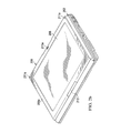
- FIG. 2 a is a perspective view illustrating an embodiment of an IHS in a laptop/notebook mode.
- FIG. 2 b is a perspective view illustrating an embodiment of the IHS of FIG. 2 a in a tablet/slate mode.
- FIG. 3 a is a perspective view illustrating an embodiment of a first latch device used with the IHS of FIGS. 2 a and 2 b.
- FIG. 3 b is a perspective view illustrating an embodiment of the first latch device of FIG. 3 a coupled to the IHS of FIGS. 2 a and 2 b.
- FIG. 3 c is a cross sectional view illustrating an embodiment of the first latch device of FIG. 3 a coupled to the IHS of FIGS. 2 a and 2 b.
- FIG. 4 a is a exploded perspective view illustrating an embodiment of a second latch device used with the IHS of FIGS. 2 a and 2 b and the first latch device of FIG. 3 a.
- FIG. 4 b is a perspective view illustrating an embodiment of the second latch device coupled to the IHS of FIGS. 2 a and 2 b.
- FIG. 4 c is a cut-away perspective view illustrating an embodiment of the second latch device coupled to the IHS of FIGS. 2 a and 2 b.
- FIG. 4 d is a cross-sectional view illustrating an embodiment of the second latch device coupled to the IHS of FIGS. 2 a and 2 b.
- FIG. 5 a is a flow chart illustrating an embodiment of a method for latching a convertible IHS.
- FIG. 5 b is a cross-sectional view illustrating an embodiment the second latch device of FIG. 4 a actuating the first latch device of FIG. 3 a in the IHS of FIGS. 2 a and 2 b to latch the convertible IHS.
- FIG. 5 c is a cross-sectional view illustrating an embodiment the second latch device of FIG. 4 a engaging the first latch device of FIG. 3 a in the IHS of FIGS. 2 a and 2 b to provide a first option for unlatching the convertible IHS.
- FIG. 5 d is a cross-sectional view illustrating an embodiment the second latch device of FIG. 4 a in the IHS of FIGS. 2 a and 2 b providing a second option for unlatching the convertible IHS.
- FIG. 6 is a cross-sectional view illustrating an embodiment the second latch device having a modified base latch member actuator.
- FIG. 7 is a cross-sectional view illustrating an embodiment the second latch device having a modified base latch member actuator.
- an IHS may include any instrumentality or aggregate of instrumentalities operable to compute, classify, process, transmit, receive, retrieve, originate, switch, store, display, manifest, detect, record, reproduce, handle, or utilize any form of information, intelligence, or data for business, scientific, control, entertainment, or other purposes.
- an IHS may be a personal computer, a PDA, a consumer electronic device, a display device or monitor, a network server or storage device, a switch router or other network communication device, or any other suitable device and may vary in size, shape, performance, functionality, and price.
- the IHS may include memory, one or more processing resources such as a central processing unit (CPU) or hardware or software control logic.
- CPU central processing unit
- Additional components of the IHS may include one or more storage devices, one or more communications ports for communicating with external devices as well as various input and output (I/O) devices, such as a keyboard, a mouse, and a video display.
- the IHS may also include one or more buses operable to transmit communications between the various hardware components.
- IHS 100 includes a processor 102 , which is connected to a bus 104 .
- Bus 104 serves as a connection between processor 102 and other components of IHS 100 .
- An input device 106 is coupled to processor 102 to provide input to processor 102 .
- Examples of input devices may include keyboards, touchscreens, pointing devices such as mouses, trackballs, and trackpads, and/or a variety of other input devices known in the art.
- Programs and data are stored on a mass storage device 108 , which is coupled to processor 102 . Examples of mass storage devices may include hard discs, optical disks, magneto-optical discs, solid-state storage devices, and/or a variety other mass storage devices known in the art.
- IHS 100 further includes a display 110 , which is coupled to processor 102 by a video controller 112 .
- a system memory 114 is coupled to processor 102 to provide the processor with fast storage to facilitate execution of computer programs by processor 102 .
- Examples of system memory may include random access memory (RAM) devices such as dynamic RAM (DRAM), synchronous DRAM (SDRAM), solid state memory devices, and/or a variety of other memory devices known in the art.
- RAM random access memory
- DRAM dynamic RAM
- SDRAM synchronous DRAM
- solid state memory devices solid state memory devices
- a chassis 116 houses some or all of the components of IHS 100 . It should be understood that other buses and intermediate circuits can be deployed between the components described above and processor 102 to facilitate interconnection between the components and the processor 102 .
- the convertible IHS 200 includes a base portion 202 having a top surface 202 a that includes a keyboard 202 b and a touchpad 202 c located adjacent the top surface 202 a .
- the base portion 202 may be the chassis 116 , described above with reference to FIG. 1 , and may house some or all of the components of the IHS 100 .
- a base latch member aperture 204 is defined by the base portion 202 , located on the top surface 202 a of the base member 202 , and is described in further detail below.
- a pair of stabilizer members 205 are located at corners of the top surface 202 a of the base portion 202 on opposite sides of the touchpad 202 c .
- the convertible IHS 200 also includes a display portion 206 having a front surface 206 a and a rear surface 206 b that is located opposite the display portion 206 from the front surface 206 a .
- a display screen 208 is located adjacent the front surface 202 a of the display portion 206 .
- a first display latch member aperture 210 a is defined by the display portion 206 , located on the front surface 206 a of the display portion 206 adjacent the display screen 208 , and is described in further detail below.
- a second display latch member aperture 210 b is defined by the display portion 206 , located on the rear surface 206 b of the display portion 206 , and is described in further detail below.
- a pair of stabilizer members 211 a e.g., protrusions, detents, etc.
- a pair of stabilizer members 211 b are located at corners of the rear surface 206 a of the display portion 202 on opposite sides of the second display latch member aperture 210 b .
- the display portion 206 is moveably coupled to the base portion 202 by a coupling 212 that allows the display portion 206 to move relative to the base portion 202 in each of a plurality of different IHS modes, described in further detail below.
- the display portion 206 is moveable about the coupling 212 through a range of motion A that is illustrated in FIG. 2 a .
- the display portion 206 may move between a closed orientation in which the display portion 206 is immediately adjacent the base portion 202 such that the display screen 208 faces the top surface 202 a of the base portion 202 , and an open orientation (illustrated) in which the display portion 206 and display screen 208 are located at an angle (e.g., between 90-120 degrees in the embodiment illustrated in FIG. 2 a ) relative to the base portion 206 .
- the display portion 206 may be rotated 180 degrees about an axis 212 a of the display portion 206 through a range of motion B that is illustrated in FIG. 2 a such that positions of the rear surface 206 b of the display portion 206 and the display screen 208 illustrated in FIG. 2 a are reversed, and then moved through the clamshell range of motion A until the display portion 206 is positioned immediately adjacent the base portion 202 , but now with the display screen 208 located opposite the display portion 206 from the base portion 202 such that the display screen 208 faces away from the top surface 206 a of the base portion 206 , as illustrated in FIG. 2 b .
- the coupling 212 includes detents to provide a user with feedback when the display portion 206 is in the proper orientation for the laptop/notebook mode and/or the tablet/slate mode.
- the stabilizer members 205 , 211 a and 211 b stabilize the display portion 206 relative to the base portion 202 .
- the positioning of the stabilizer members 211 a and 221 b at the corners of the display portion 206 opposite the base portion 202 and away from the coupling 212 provides improved control of display portion movement about the coupling 212 , and ensure that there are no protrusions on the base portion 202 that can damage components of the display portion 206 (e.g., LCD glass.) While a specific embodiment of a convertible IHS 200 has been described above that includes the coupling 212 to allow conversion from a laptop/notebook mode to a tablet/slate mode, one of skill in the art will recognize that a variety of other convertible IHS's with different moveable couplings for conversion between IHS modes will fall within the scope of the presented disclosure.
- the base latch device 300 includes a mounting member 302 that defines a pair of spaced apart mounting apertures 302 a .
- a base latch member 304 includes a securing surface 304 a and is moveably coupled to the mounting member 302 through a mounting rod 306 that is located in the mounting apertures 302 a and extends through an aperture 304 b defined by the base latch member 304 .
- the base latch member 304 includes a magnetic material or a metal material. The moveable coupling of the base latch member 304 to the mounting member 302 allows the base latch member 304 to move through a range of motion C.
- a resilient member 308 such as, for example, a spring, is coupled to the base latch member 304 to bias the base latch member 304 as described in further detail below.
- the mounting member 302 may be mounted in a housing 202 d defined by the base portion 202 such that the base latch member 304 is located adjacent the base latch member aperture 204 , as illustrated in FIG. 3 c .
- the resilient member 308 biases the base latch member 304 into a retracted position D, illustrated in FIGS. 3 b and 3 c , in which the base latch member 304 is retracted into the housing 202 d define by the base portion 202 and does not extend through the base latch member aperture 204 and out past the top surface 202 a of the base portion 202 .
- a force may be applied to the base latch member 304 such that the bias provided by the resilient member 208 is overcome and the base latch member 304 becomes positioned in an extended position E, illustrated in FIG. 3 a.
- the display latch device 400 includes a display latch member 402 including a base 402 a and an activator member 402 b extending from the base 402 a .
- the base 402 a defines an actuator housing 404 and includes a first release member 406 a (visible in FIGS. 4 a and 4 b ) extending from a first side 402 aa of the base 402 a and a second release member 406 b (visible in FIG. 4 b ) extending from a second side 402 ab of the base 402 a .
- a base member actuator 408 is located in the actuator housing 404 .
- the base member actuator 408 includes a magnetic material or a metal material.
- the display latch device 400 also includes a first side latch engagement member 410 having a rod 410 a coupled with a resilient member 410 b , along with an actuator portion 410 c that is located on a distal end of the rod 410 a , defines a display latch member channel 410 d , and includes a stop member 410 e located opposite the actuator portion 410 c from the display latch member channel 410 d .
- a second side latch engagement member 412 is substantially similar to the first side latch engagement member 410 and includes a rod 412 a coupled with a resilient member 412 b , along with an actuator portion 412 c that is located on a distal end of the rod 412 a , defines a display latch member channel 412 d , and includes a stop member 412 e located opposite the actuator portion 412 c from the display latch member channel 412 d.
- the display latch member 402 is coupled to the display portion 206 such that the activator member 402 b is located adjacent a surface on the display portion 206 that extends between the front surface 206 a and the rear surface 206 b , as illustrated in FIG. 4 b , and the base 402 a extends into a housing 209 defined by the display portion 206 , as illustrated in FIGS. 4 c and 4 d .
- the first side latch engagement member 410 and the second side latch engagement member 412 are coupled to the display portion 206 such that they are on opposite sides of the base 402 a of the display latch member 402 , as illustrated in FIGS. 4 c and 4 d .
- the display portion 206 includes engagement member mounts 207 a and 207 b that accept the rods 410 a and 412 a , respectively, on the first side latch engagement member 410 and the second side latch engagement member 412 , respectively.
- the display portion 206 also includes engagement member stops 207 c (visible in FIGS. 4 c and 4 d ) and 207 d (visible in FIG. 4 d ), that are operable to engage the stop members 410 e and 412 e , respectively, on the first side latch engagement member 410 and the second side latch engagement member 412 , respectively, as described in further detail below.
- the resilient member 410 b engages the engagement member mount 207 a to bias the first side latch engagement member 410 in a direction E until the stop member 410 e on the first side latch engagement member 410 engages the engagement stop 207 c in a base latch member engagement position, and the resilient member 412 b engages the engagement member mount 207 b to bias the second side latch engagement member 412 in a direction F until the stop member 412 e on the second side latch engagement member 412 engages the engagement stop 207 d in a base latch member engagement position, as illustrated in FIG. 4 d.
- the method 500 begins at block 502 where a convertible IHS in provided in a first mode.
- the convertible IHS 200 is provided in the laptop/notebook mode illustrated and discussed above with reference to FIG. 2 a .
- the method 500 then proceeds to block 504 where a display portion is moved adjacent a base portion to actuate a base latch member.
- a user may wish to latch the display portion 206 to the base portion 202 when the convertible IHS 200 is not being used.
- the display portion 206 may be moved from the position illustrated in FIG.
- the resilient member 308 biases the base latch member 304 in the base portion 202 into the retracted position D, illustrated in FIGS. 3 b and 3 c .
- the base member actuator 408 moves adjacent the base latch member 304 and provides a force on the base latch member 304 that overcomes the bias provided by the resilient member 208 and moves the base latch member 304 through its range of motion C from the retracted position D to the extended position E, illustrated in FIG. 5 b .
- the force provided on the base latch member 304 from the base member actuator 408 is due to a magnetic attraction between the base latch member 304 and the base member actuator 408 (e.g., one of the base latch member 304 and the base member actuator 408 is a magnetic material while the other is a metal material.) Movement of the base latch member 304 into the extended position E results in the base latch member 304 extending through the base latch member aperture 204 defined by the base portion 202 , out past the top surface 202 a of the base portion 202 , through the first display latch member aperture 210 a defined by the display portion 206 , and into the housing 209 defined by the display portion 206 such that the securing surface 304 a on the base latch member 304 is located immediately adjacent the stop member 410 e on the first side latch engagement member 410 , as illustrated in FIG.
- the stabilizer members 205 on the base portion 202 engage the stabilizer members 211 a on the display portion 206 .
- the base latch member 304 may engage some portion of the display latch device 400 to provide an user-audible noise (e.g., a ‘click’) to provide feedback to the user that the IHS is latched and secure.
- the method 500 then proceeds to block 506 where movement of the display portion is resisted with the base latch member.
- the base latch member 304 in the extended position E, any attempt to move the display portion 206 away from the base portion 202 will be resisted by the engagement of the securing secure 304 a on the base latch member 304 and the stop member 410 e on the first side latch engagement member 410 .
- the stabilizer members 205 on the base portion 202 engaging the stabilizer members 211 a on the display portion 206
- movement of the display portion 206 relative to the base portion 202 in a plane that is parallel to the top surface 202 a of the base portion 202 is resisted.
- the latching system components the base latching member and the first side latch engagement member 410
- the method 500 proceeds to block 508 where the display portion is unlatched from the base portion.
- a user may wish to unlatch the display portion 206 from the base portion 202 in order to use the convertible IHS 200 .
- the latching system described above gives the user two unlatching options for doing so. Using a first unlatching option, illustrated in FIG. 5 c , the user moves the display latch member 402 from the position illustrated in FIG. 5 b in a direction G.
- Movement of the display latch member 402 in the direction G causes the base 402 a of the display latch member 402 to engage the actuator portion 412 c of second side latch engagement member 412 and overcome the bias provided by the resilient member 412 b to move the second side latch engagement member 412 such that the first release member 406 a on the base 402 a of the display latch member 402 engages the base latch member 304 and moves the base latch member 304 out of the extended position E and into a release position H, as illustrated in FIG. 5 c .
- the display portion 206 is unlatched from the base portion 202 and may be moved away from the base portion 202 and into the position illustrated in FIG. 2 a .
- Movement of the display portion 206 away from the base portion 202 moves the base member actuator 408 away from the base latch member 304 such that the force on the base latch member 304 from the base member actuator 408 is no longer present, and the bias provided by resilient member 208 on the base latch member 304 will move the base member into the retracted position D, illustrated in FIGS. 3 b and 3 c.
- FIG. 5 d Using a second unlatching option, illustrated in FIG. 5 d , the user moves the display latch member 402 from the position illustrated in FIG. 5 b in a direction I. Movement of the display latch member 402 in the direction I causes the base 402 a of the display latch member 402 to engage the actuator portion 410 c of first side latch engagement member 410 and overcome the bias provided by the resilient member 412 b to move the first side latch engagement member 410 until the stop member 410 e on the first side latch engagement member 410 is no longer adjacent the securing surface 304 a on the base latch member 304 , as illustrated in FIG. 5 d .
- the display portion 206 is unlatched from the base portion 202 and may be moved away from the base portion 202 and into the position illustrated in FIG. 2 a . Movement of the display portion 206 away from the base portion 202 moves the base member actuator 408 away from the base latch member 304 such that the force on the base latch member 304 from the base member actuator 408 is no longer present, and the bias provided by resilient member 208 on the base latch member 304 will move the base member into the retracted position D, illustrated in FIGS. 3 b and 3 c.
- a chamfer lead-in may be added to a portion of the first side latch engagement member 410 that is adjacent the front surface 206 a of the display portion 206 and that engages the base latch member 304 , and to a portion of the second side latch engagement member 412 that is adjacent the rear surface 206 b of the display portion 206 and that engages the base latch member 304 .
- the chamfer lead-ins on the first side latch engagement member 410 and the second side latch engagement member 412 can be helpful in preventing binding of the base latch member 304 with the display latch device 400 . For example, normally the base latch member 304 will remain in the retracted position D until the display portion 206 is brought close enough to the base portion 202 .
- the base latch member 204 and the display latch device 400 may be engaged, it may be possible to unlatched the display portion 206 from the base portion 202 (as described above with reference to FIGS. 5 c and 5 d ) and slightly move the display portion 206 relative to the base portion 202 to reset one of the first side latch engagement member 410 or the second side latch engagement member 412 (depending on the mode of the IHS) without the base latch member 304 moving to the retracted position D.
- the method 500 then proceeds to block 510 where a convertible IHS in provided in a second mode.
- the convertible IHS 200 is converted to the tablet/slate mode illustrated and discussed above with reference to FIGS. 2 a and 2 b .
- the method 500 may then repeat blocks 504 , 506 , and 508 substantially as discussed above but with the display portion in a reversed orientation such that, once latched, the display portion 206 is in the orientation illustrated in FIG. 2 b .
- the structure of the latch device 400 e.g., the second latch member 402 and the first and second side latch engagement members 410 and 412
- the display portion 206 e.g., the first and second display latch member apertures 210 a and 210 b
- the structure of the latch device 400 e.g., the second latch member 402 and the first and second side latch engagement members 410 and 412
- the display portion 206 e.g., the first and second display latch member apertures 210 a and 210 b
- the display portion 206 is moved through the range of motion A until the display portion 206 is positioned immediately adjacent the base portion 202 , but now with rear surface 206 b of the display screen 208 facing the top surface 202 a of the base portion 202 such that the display screen 208 faces away from the top surface 206 a of the base portion 206 , as illustrated in FIG. 2 b .
- the base member actuator 408 provides the force on the base latch member 304 that moves the base latch member 304 into the extended position E such that the base latch member 304 extends through the base latch member aperture 204 defined by the base portion 202 , out past the top surface 202 a of the base portion 202 , through the second display latch member aperture 210 b defined by the display portion 206 , and into the housing 209 defined by the display portion 206 such that the a securing surface 304 a on the base latch member 304 is located immediately adjacent the stop member 412 e on the second side latch engagement member 412 .
- any attempt to move the display portion 206 away from the base portion 202 will be resisted by the engagement of the securing secure 304 a on the base latch member 304 and the stop member 412 e on the second side latch engagement member 412 . Furthermore, with the stabilizer members 205 on the base portion 202 engaging the stabilizer members 211 b on the display portion 206 , movement of the display portion 206 relative to the base portion 202 in a plane that is parallel to the top surface 202 a of the base portion 202 is resisted.
- the display portion 206 may then be unlatched from the base portion 202 using the first unlatching option that moves the display latch member 402 to engage the actuator portion 410 c of first side latch engagement member 410 until the second release member 406 b on the display latch member 402 engages the base latch member 304 and moves the base latch member 304 into the release position H so that the display portion 206 is unlatched from the base portion 202 .
- the display portion 206 may also be unlatched from the base portion 202 using the second unlatching option and moving the display latch member 402 to cause the base 402 a of the display latch member 402 to engage the actuator portion 412 c of second side latch engagement member 412 until the stop member 412 e on the second side latch engagement member 412 is no longer adjacent the securing surface 304 a on the base latch member 304 so that the display portion 206 is unlatched from the base portion 202 .
- the latching system described above provides a user with one handed operation to latch and unlatch the an IHS in either of a laptop/notebook mode and a tablet/slate mode.
- FIGS. 6 and 7 embodiments of display latch devices 600 and 700 are illustrated that are substantially similar to the display latch device 400 described above with reference to FIGS. 4 a , 4 b, 4 c, 4 d, 5 a, 5 b , 5 c , and 5 d , with the provision of a modified base member actuator 602 in the display latch device 600 and a modified base member actuator 702 in the display latch device 700 replacing the base member actuator device 408 .
- the modified base member actuators 602 and 702 are magnets having specific pole orientations.
- modified base member actuator 602 includes a pair of poles, with a N pole located adjacent the first side latch engagement member 410 and a S pole located adjacent the second side latch engagement member 412
- modified base member actuator 702 includes a four poles, with a stacked N pole and S pole located adjacent the first side latch engagement member 410 and a stacked S pole and N pole located adjacent the second side latch engagement member 412 .
- pole placement and orientation can effect the actuation of the base latch member by creating a magnetic field that is better suited to position the base latching member 304 to latch the system.
- such an embodiment is not meant to limit the present disclosure, and a variety of simpler and more complex magnet are envisioned as falling within its scope.
- a system and method allow a display portion on a convertible IHS to be latched to a base portion in either of a laptop/notebook mode and a tablet/slate mode.
- a first latch member remains retracted into the base portion when not in use for latching to prevent damage to the convertible IHS or injury to the user, and is then automatically drawn out of the base portion when the display portion is brought near in order to provide for latching.
- the system and method allow a user to then unlatch the display portion from the base portion by moving a second latch member in either of pair of directions such that the user does not need to determine the IHS mode to unlatch or remember an actuation direction for unlatching for each IHS mode.
- the second latch member for unlatching the system is included on the display portion, which reduces the possibility of re-latch that exists when the unlatching mechanism is included on the base portion (i.e., during the transition of the hand from the base portion to the display portion to lift the display portion.)
Landscapes
- Engineering & Computer Science (AREA)
- Computer Hardware Design (AREA)
- Physics & Mathematics (AREA)
- Theoretical Computer Science (AREA)
- Human Computer Interaction (AREA)
- General Engineering & Computer Science (AREA)
- General Physics & Mathematics (AREA)
- Mechanical Engineering (AREA)
- Microelectronics & Electronic Packaging (AREA)
- Mathematical Physics (AREA)
- Electromagnetism (AREA)
- Casings For Electric Apparatus (AREA)
Abstract
Description
Claims (20)
Priority Applications (1)
| Application Number | Priority Date | Filing Date | Title |
|---|---|---|---|
| US13/028,327 US8576562B2 (en) | 2011-02-16 | 2011-02-16 | Latching system for convertible information handling system |
Applications Claiming Priority (1)
| Application Number | Priority Date | Filing Date | Title |
|---|---|---|---|
| US13/028,327 US8576562B2 (en) | 2011-02-16 | 2011-02-16 | Latching system for convertible information handling system |
Publications (2)
| Publication Number | Publication Date |
|---|---|
| US20120206873A1 US20120206873A1 (en) | 2012-08-16 |
| US8576562B2 true US8576562B2 (en) | 2013-11-05 |
Family
ID=46636729
Family Applications (1)
| Application Number | Title | Priority Date | Filing Date |
|---|---|---|---|
| US13/028,327 Expired - Fee Related US8576562B2 (en) | 2011-02-16 | 2011-02-16 | Latching system for convertible information handling system |
Country Status (1)
| Country | Link |
|---|---|
| US (1) | US8576562B2 (en) |
Cited By (4)
| Publication number | Priority date | Publication date | Assignee | Title |
|---|---|---|---|---|
| US20160102481A1 (en) * | 2011-01-24 | 2016-04-14 | Carefusion 303, Inc. | Self-aligning modular latch |
| US9851745B2 (en) * | 2012-09-12 | 2017-12-26 | Hewlett-Packard Development Company, L.P. | Latch for a computer case |
| US11150701B1 (en) | 2021-04-05 | 2021-10-19 | Ibenzer Inc. | Case for a computing device |
| US12232285B2 (en) * | 2023-02-21 | 2025-02-18 | Quanta Computer Inc. | Mounting assembly with nested brackets |
Families Citing this family (4)
| Publication number | Priority date | Publication date | Assignee | Title |
|---|---|---|---|---|
| TWI423757B (en) * | 2011-05-09 | 2014-01-11 | 緯創資通股份有限公司 | Fixing mechanism and electronic device having the same |
| CN104756037B (en) | 2012-11-09 | 2019-03-12 | 惠普发展公司,有限责任合伙企业 | Magnets at display assembly and base |
| CN104111696B (en) | 2013-04-17 | 2017-05-10 | 纬创资通(昆山)有限公司 | Fastening mechanism and portable electronic device |
| WO2017077667A1 (en) * | 2015-11-06 | 2017-05-11 | パナソニックIpマネジメント株式会社 | Electronic device and latch mechanism |
Citations (12)
| Publication number | Priority date | Publication date | Assignee | Title |
|---|---|---|---|---|
| US5253142A (en) * | 1991-09-19 | 1993-10-12 | Cal-Comp Electronics, Inc. | Body structure for a pocket computer having a fastener with multiple spaced apart elements |
| US6034867A (en) * | 1996-06-20 | 2000-03-07 | Samsung Electronics Co., Ltd. | Portable computer having a locking assembly |
| US20030011972A1 (en) * | 2001-07-13 | 2003-01-16 | Koo Ja-Goun | Control of LCD display backlight by actuation of a latch in a notebook computer |
| US6517129B1 (en) * | 2002-04-15 | 2003-02-11 | Compal Electronics, Inc. | Lock device for an electronic appliance |
| US6659516B2 (en) | 2001-01-05 | 2003-12-09 | Apple Computer, Inc. | Locking system for a portable computer |
| US20050036284A1 (en) * | 2003-08-11 | 2005-02-17 | Lg Electronics Inc. | Bidirectional latch assembly and electronic apparatuses using the same |
| US20060002062A1 (en) * | 2004-07-02 | 2006-01-05 | Kwon Hae O | Latch device for portable computer |
| US20060056140A1 (en) | 2004-09-10 | 2006-03-16 | Lev Jeffrey A | Push-button latching mechanism |
| US20070070593A1 (en) * | 2005-09-27 | 2007-03-29 | Asustek Computer Inc. | Fastening mechanism |
| US20070171604A1 (en) * | 2006-01-21 | 2007-07-26 | Hon Hai Precision Industry Co., Ltd. | Foldable electronic device having a latch mechanism |
| US20080087050A1 (en) * | 2006-10-13 | 2008-04-17 | Hon Hai Precision Industry Co., Ltd. | Lock device for foldable electronic apparatus |
| US20080256805A1 (en) * | 2007-04-19 | 2008-10-23 | Ian Maddison | Handle latching mechanism |
-
2011
- 2011-02-16 US US13/028,327 patent/US8576562B2/en not_active Expired - Fee Related
Patent Citations (12)
| Publication number | Priority date | Publication date | Assignee | Title |
|---|---|---|---|---|
| US5253142A (en) * | 1991-09-19 | 1993-10-12 | Cal-Comp Electronics, Inc. | Body structure for a pocket computer having a fastener with multiple spaced apart elements |
| US6034867A (en) * | 1996-06-20 | 2000-03-07 | Samsung Electronics Co., Ltd. | Portable computer having a locking assembly |
| US6659516B2 (en) | 2001-01-05 | 2003-12-09 | Apple Computer, Inc. | Locking system for a portable computer |
| US20030011972A1 (en) * | 2001-07-13 | 2003-01-16 | Koo Ja-Goun | Control of LCD display backlight by actuation of a latch in a notebook computer |
| US6517129B1 (en) * | 2002-04-15 | 2003-02-11 | Compal Electronics, Inc. | Lock device for an electronic appliance |
| US20050036284A1 (en) * | 2003-08-11 | 2005-02-17 | Lg Electronics Inc. | Bidirectional latch assembly and electronic apparatuses using the same |
| US20060002062A1 (en) * | 2004-07-02 | 2006-01-05 | Kwon Hae O | Latch device for portable computer |
| US20060056140A1 (en) | 2004-09-10 | 2006-03-16 | Lev Jeffrey A | Push-button latching mechanism |
| US20070070593A1 (en) * | 2005-09-27 | 2007-03-29 | Asustek Computer Inc. | Fastening mechanism |
| US20070171604A1 (en) * | 2006-01-21 | 2007-07-26 | Hon Hai Precision Industry Co., Ltd. | Foldable electronic device having a latch mechanism |
| US20080087050A1 (en) * | 2006-10-13 | 2008-04-17 | Hon Hai Precision Industry Co., Ltd. | Lock device for foldable electronic apparatus |
| US20080256805A1 (en) * | 2007-04-19 | 2008-10-23 | Ian Maddison | Handle latching mechanism |
Cited By (8)
| Publication number | Priority date | Publication date | Assignee | Title |
|---|---|---|---|---|
| US20160102481A1 (en) * | 2011-01-24 | 2016-04-14 | Carefusion 303, Inc. | Self-aligning modular latch |
| US10435918B2 (en) * | 2011-01-24 | 2019-10-08 | Carefusion 303, Inc. | Self-aligning modular latch |
| US11466476B2 (en) | 2011-01-24 | 2022-10-11 | Carefusion 303, Inc. | Self-aligning modular latch |
| US11821239B2 (en) | 2011-01-24 | 2023-11-21 | Carefusion 303, Inc. | Self-aligning modular latch |
| US12196007B2 (en) | 2011-01-24 | 2025-01-14 | Carefusion 303, Inc. | Self-aligning modular latch |
| US9851745B2 (en) * | 2012-09-12 | 2017-12-26 | Hewlett-Packard Development Company, L.P. | Latch for a computer case |
| US11150701B1 (en) | 2021-04-05 | 2021-10-19 | Ibenzer Inc. | Case for a computing device |
| US12232285B2 (en) * | 2023-02-21 | 2025-02-18 | Quanta Computer Inc. | Mounting assembly with nested brackets |
Also Published As
| Publication number | Publication date |
|---|---|
| US20120206873A1 (en) | 2012-08-16 |
Similar Documents
| Publication | Publication Date | Title |
|---|---|---|
| US8576562B2 (en) | Latching system for convertible information handling system | |
| US7480154B2 (en) | Method and apparatus for securing a cable management system | |
| US8405966B2 (en) | Memory carrier and IHS coupling system | |
| US8879250B2 (en) | Tablet support system | |
| US8279596B2 (en) | Fan mounting system | |
| US8120904B2 (en) | Chassis mounting system | |
| US9054473B2 (en) | Processor loading system | |
| US8582306B2 (en) | Modular component chassis coupling system | |
| US7566033B2 (en) | Method and apparatus for controlling display rotation on an information handling system | |
| US20160316585A1 (en) | Chassis drawer for modular information handling resources | |
| US8432688B2 (en) | IHS securing system | |
| US7460365B2 (en) | Interposer for a drive bay | |
| US8605441B2 (en) | Latching system for a moveable component in a removable IHS | |
| US8437133B2 (en) | Latching module mounting system | |
| US8144463B2 (en) | Card retention system | |
| US20100323237A1 (en) | Battery connector coupling | |
| US12604428B2 (en) | Information handling system bezel latch and lock | |
| US10948951B2 (en) | Card/chassis coupling system | |
| US20160124465A1 (en) | Retractable docking system | |
| US7643303B1 (en) | Rotating and translating control panel | |
| US11599160B2 (en) | Computing device support surface mounting system | |
| US20130230998A1 (en) | Memory device latching system | |
| US12374825B2 (en) | Connector fastener extension system | |
| US20240258720A1 (en) | Connector fastener extension system | |
| US9237664B2 (en) | Multi-module keying system |
Legal Events
| Date | Code | Title | Description |
|---|---|---|---|
| AS | Assignment |
Owner name: DELL PRODUCTS L.P., TEXAS Free format text: ASSIGNMENT OF ASSIGNORS INTEREST;ASSIGNORS:SCHWAGER, MARK A.;TOSH, ANDREW;REEL/FRAME:025818/0305 Effective date: 20110201 |
|
| STCF | Information on status: patent grant |
Free format text: PATENTED CASE |
|
| FEPP | Fee payment procedure |
Free format text: PAYOR NUMBER ASSIGNED (ORIGINAL EVENT CODE: ASPN); ENTITY STATUS OF PATENT OWNER: LARGE ENTITY |
|
| AS | Assignment |
Owner name: BANK OF AMERICA, N.A., AS ADMINISTRATIVE AGENT, TE Free format text: PATENT SECURITY AGREEMENT (ABL);ASSIGNORS:DELL INC.;APPASSURE SOFTWARE, INC.;ASAP SOFTWARE EXPRESS, INC.;AND OTHERS;REEL/FRAME:031898/0001 Effective date: 20131029 Owner name: BANK OF AMERICA, N.A., AS ADMINISTRATIVE AGENT, TEXAS Free format text: PATENT SECURITY AGREEMENT (ABL);ASSIGNORS:DELL INC.;APPASSURE SOFTWARE, INC.;ASAP SOFTWARE EXPRESS, INC.;AND OTHERS;REEL/FRAME:031898/0001 Effective date: 20131029 Owner name: BANK OF AMERICA, N.A., AS COLLATERAL AGENT, NORTH CAROLINA Free format text: PATENT SECURITY AGREEMENT (TERM LOAN);ASSIGNORS:DELL INC.;APPASSURE SOFTWARE, INC.;ASAP SOFTWARE EXPRESS, INC.;AND OTHERS;REEL/FRAME:031899/0261 Effective date: 20131029 Owner name: BANK OF NEW YORK MELLON TRUST COMPANY, N.A., AS FIRST LIEN COLLATERAL AGENT, TEXAS Free format text: PATENT SECURITY AGREEMENT (NOTES);ASSIGNORS:APPASSURE SOFTWARE, INC.;ASAP SOFTWARE EXPRESS, INC.;BOOMI, INC.;AND OTHERS;REEL/FRAME:031897/0348 Effective date: 20131029 Owner name: BANK OF NEW YORK MELLON TRUST COMPANY, N.A., AS FI Free format text: PATENT SECURITY AGREEMENT (NOTES);ASSIGNORS:APPASSURE SOFTWARE, INC.;ASAP SOFTWARE EXPRESS, INC.;BOOMI, INC.;AND OTHERS;REEL/FRAME:031897/0348 Effective date: 20131029 Owner name: BANK OF AMERICA, N.A., AS COLLATERAL AGENT, NORTH Free format text: PATENT SECURITY AGREEMENT (TERM LOAN);ASSIGNORS:DELL INC.;APPASSURE SOFTWARE, INC.;ASAP SOFTWARE EXPRESS, INC.;AND OTHERS;REEL/FRAME:031899/0261 Effective date: 20131029 |
|
| AS | Assignment |
Owner name: SECUREWORKS, INC., GEORGIA Free format text: RELEASE BY SECURED PARTY;ASSIGNOR:BANK OF AMERICA, N.A., AS ADMINISTRATIVE AGENT;REEL/FRAME:040065/0216 Effective date: 20160907 Owner name: COMPELLANT TECHNOLOGIES, INC., MINNESOTA Free format text: RELEASE BY SECURED PARTY;ASSIGNOR:BANK OF AMERICA, N.A., AS ADMINISTRATIVE AGENT;REEL/FRAME:040065/0216 Effective date: 20160907 Owner name: DELL USA L.P., TEXAS Free format text: RELEASE BY SECURED PARTY;ASSIGNOR:BANK OF AMERICA, N.A., AS ADMINISTRATIVE AGENT;REEL/FRAME:040065/0216 Effective date: 20160907 Owner name: DELL SOFTWARE INC., CALIFORNIA Free format text: RELEASE BY SECURED PARTY;ASSIGNOR:BANK OF AMERICA, N.A., AS ADMINISTRATIVE AGENT;REEL/FRAME:040065/0216 Effective date: 20160907 Owner name: PEROT SYSTEMS CORPORATION, TEXAS Free format text: RELEASE BY SECURED PARTY;ASSIGNOR:BANK OF AMERICA, N.A., AS ADMINISTRATIVE AGENT;REEL/FRAME:040065/0216 Effective date: 20160907 Owner name: ASAP SOFTWARE EXPRESS, INC., ILLINOIS Free format text: RELEASE BY SECURED PARTY;ASSIGNOR:BANK OF AMERICA, N.A., AS ADMINISTRATIVE AGENT;REEL/FRAME:040065/0216 Effective date: 20160907 Owner name: DELL MARKETING L.P., TEXAS Free format text: RELEASE BY SECURED PARTY;ASSIGNOR:BANK OF AMERICA, N.A., AS ADMINISTRATIVE AGENT;REEL/FRAME:040065/0216 Effective date: 20160907 Owner name: APPASSURE SOFTWARE, INC., VIRGINIA Free format text: RELEASE BY SECURED PARTY;ASSIGNOR:BANK OF AMERICA, N.A., AS ADMINISTRATIVE AGENT;REEL/FRAME:040065/0216 Effective date: 20160907 Owner name: DELL INC., TEXAS Free format text: RELEASE BY SECURED PARTY;ASSIGNOR:BANK OF AMERICA, N.A., AS ADMINISTRATIVE AGENT;REEL/FRAME:040065/0216 Effective date: 20160907 Owner name: DELL PRODUCTS L.P., TEXAS Free format text: RELEASE BY SECURED PARTY;ASSIGNOR:BANK OF AMERICA, N.A., AS ADMINISTRATIVE AGENT;REEL/FRAME:040065/0216 Effective date: 20160907 Owner name: FORCE10 NETWORKS, INC., CALIFORNIA Free format text: RELEASE BY SECURED PARTY;ASSIGNOR:BANK OF AMERICA, N.A., AS ADMINISTRATIVE AGENT;REEL/FRAME:040065/0216 Effective date: 20160907 Owner name: WYSE TECHNOLOGY L.L.C., CALIFORNIA Free format text: RELEASE BY SECURED PARTY;ASSIGNOR:BANK OF AMERICA, N.A., AS ADMINISTRATIVE AGENT;REEL/FRAME:040065/0216 Effective date: 20160907 Owner name: CREDANT TECHNOLOGIES, INC., TEXAS Free format text: RELEASE BY SECURED PARTY;ASSIGNOR:BANK OF AMERICA, N.A., AS ADMINISTRATIVE AGENT;REEL/FRAME:040065/0216 Effective date: 20160907 |
|
| AS | Assignment |
Owner name: COMPELLENT TECHNOLOGIES, INC., MINNESOTA Free format text: RELEASE BY SECURED PARTY;ASSIGNOR:BANK OF AMERICA, N.A., AS COLLATERAL AGENT;REEL/FRAME:040040/0001 Effective date: 20160907 Owner name: DELL MARKETING L.P., TEXAS Free format text: RELEASE BY SECURED PARTY;ASSIGNOR:BANK OF AMERICA, N.A., AS COLLATERAL AGENT;REEL/FRAME:040040/0001 Effective date: 20160907 Owner name: DELL USA L.P., TEXAS Free format text: RELEASE BY SECURED PARTY;ASSIGNOR:BANK OF AMERICA, N.A., AS COLLATERAL AGENT;REEL/FRAME:040040/0001 Effective date: 20160907 Owner name: PEROT SYSTEMS CORPORATION, TEXAS Free format text: RELEASE BY SECURED PARTY;ASSIGNOR:BANK OF AMERICA, N.A., AS COLLATERAL AGENT;REEL/FRAME:040040/0001 Effective date: 20160907 Owner name: APPASSURE SOFTWARE, INC., VIRGINIA Free format text: RELEASE BY SECURED PARTY;ASSIGNOR:BANK OF AMERICA, N.A., AS COLLATERAL AGENT;REEL/FRAME:040040/0001 Effective date: 20160907 Owner name: SECUREWORKS, INC., GEORGIA Free format text: RELEASE BY SECURED PARTY;ASSIGNOR:BANK OF AMERICA, N.A., AS COLLATERAL AGENT;REEL/FRAME:040040/0001 Effective date: 20160907 Owner name: DELL INC., TEXAS Free format text: RELEASE BY SECURED PARTY;ASSIGNOR:BANK OF AMERICA, N.A., AS COLLATERAL AGENT;REEL/FRAME:040040/0001 Effective date: 20160907 Owner name: FORCE10 NETWORKS, INC., CALIFORNIA Free format text: RELEASE BY SECURED PARTY;ASSIGNOR:BANK OF AMERICA, N.A., AS COLLATERAL AGENT;REEL/FRAME:040040/0001 Effective date: 20160907 Owner name: DELL SOFTWARE INC., CALIFORNIA Free format text: RELEASE BY SECURED PARTY;ASSIGNOR:BANK OF AMERICA, N.A., AS COLLATERAL AGENT;REEL/FRAME:040040/0001 Effective date: 20160907 Owner name: CREDANT TECHNOLOGIES, INC., TEXAS Free format text: RELEASE BY SECURED PARTY;ASSIGNOR:BANK OF AMERICA, N.A., AS COLLATERAL AGENT;REEL/FRAME:040040/0001 Effective date: 20160907 Owner name: DELL PRODUCTS L.P., TEXAS Free format text: RELEASE BY SECURED PARTY;ASSIGNOR:BANK OF AMERICA, N.A., AS COLLATERAL AGENT;REEL/FRAME:040040/0001 Effective date: 20160907 Owner name: ASAP SOFTWARE EXPRESS, INC., ILLINOIS Free format text: RELEASE BY SECURED PARTY;ASSIGNOR:BANK OF AMERICA, N.A., AS COLLATERAL AGENT;REEL/FRAME:040040/0001 Effective date: 20160907 Owner name: WYSE TECHNOLOGY L.L.C., CALIFORNIA Free format text: RELEASE BY SECURED PARTY;ASSIGNOR:BANK OF AMERICA, N.A., AS COLLATERAL AGENT;REEL/FRAME:040040/0001 Effective date: 20160907 Owner name: DELL PRODUCTS L.P., TEXAS Free format text: RELEASE BY SECURED PARTY;ASSIGNOR:BANK OF NEW YORK MELLON TRUST COMPANY, N.A., AS COLLATERAL AGENT;REEL/FRAME:040065/0618 Effective date: 20160907 Owner name: DELL USA L.P., TEXAS Free format text: RELEASE BY SECURED PARTY;ASSIGNOR:BANK OF NEW YORK MELLON TRUST COMPANY, N.A., AS COLLATERAL AGENT;REEL/FRAME:040065/0618 Effective date: 20160907 Owner name: FORCE10 NETWORKS, INC., CALIFORNIA Free format text: RELEASE BY SECURED PARTY;ASSIGNOR:BANK OF NEW YORK MELLON TRUST COMPANY, N.A., AS COLLATERAL AGENT;REEL/FRAME:040065/0618 Effective date: 20160907 Owner name: DELL INC., TEXAS Free format text: RELEASE BY SECURED PARTY;ASSIGNOR:BANK OF NEW YORK MELLON TRUST COMPANY, N.A., AS COLLATERAL AGENT;REEL/FRAME:040065/0618 Effective date: 20160907 Owner name: APPASSURE SOFTWARE, INC., VIRGINIA Free format text: RELEASE BY SECURED PARTY;ASSIGNOR:BANK OF NEW YORK MELLON TRUST COMPANY, N.A., AS COLLATERAL AGENT;REEL/FRAME:040065/0618 Effective date: 20160907 Owner name: CREDANT TECHNOLOGIES, INC., TEXAS Free format text: RELEASE BY SECURED PARTY;ASSIGNOR:BANK OF NEW YORK MELLON TRUST COMPANY, N.A., AS COLLATERAL AGENT;REEL/FRAME:040065/0618 Effective date: 20160907 Owner name: PEROT SYSTEMS CORPORATION, TEXAS Free format text: RELEASE BY SECURED PARTY;ASSIGNOR:BANK OF NEW YORK MELLON TRUST COMPANY, N.A., AS COLLATERAL AGENT;REEL/FRAME:040065/0618 Effective date: 20160907 Owner name: SECUREWORKS, INC., GEORGIA Free format text: RELEASE BY SECURED PARTY;ASSIGNOR:BANK OF NEW YORK MELLON TRUST COMPANY, N.A., AS COLLATERAL AGENT;REEL/FRAME:040065/0618 Effective date: 20160907 Owner name: COMPELLENT TECHNOLOGIES, INC., MINNESOTA Free format text: RELEASE BY SECURED PARTY;ASSIGNOR:BANK OF NEW YORK MELLON TRUST COMPANY, N.A., AS COLLATERAL AGENT;REEL/FRAME:040065/0618 Effective date: 20160907 Owner name: WYSE TECHNOLOGY L.L.C., CALIFORNIA Free format text: RELEASE BY SECURED PARTY;ASSIGNOR:BANK OF NEW YORK MELLON TRUST COMPANY, N.A., AS COLLATERAL AGENT;REEL/FRAME:040065/0618 Effective date: 20160907 Owner name: DELL SOFTWARE INC., CALIFORNIA Free format text: RELEASE BY SECURED PARTY;ASSIGNOR:BANK OF NEW YORK MELLON TRUST COMPANY, N.A., AS COLLATERAL AGENT;REEL/FRAME:040065/0618 Effective date: 20160907 Owner name: ASAP SOFTWARE EXPRESS, INC., ILLINOIS Free format text: RELEASE BY SECURED PARTY;ASSIGNOR:BANK OF NEW YORK MELLON TRUST COMPANY, N.A., AS COLLATERAL AGENT;REEL/FRAME:040065/0618 Effective date: 20160907 Owner name: DELL MARKETING L.P., TEXAS Free format text: RELEASE BY SECURED PARTY;ASSIGNOR:BANK OF NEW YORK MELLON TRUST COMPANY, N.A., AS COLLATERAL AGENT;REEL/FRAME:040065/0618 Effective date: 20160907 |
|
| AS | Assignment |
Owner name: CREDIT SUISSE AG, CAYMAN ISLANDS BRANCH, AS COLLATERAL AGENT, NORTH CAROLINA Free format text: SECURITY AGREEMENT;ASSIGNORS:ASAP SOFTWARE EXPRESS, INC.;AVENTAIL LLC;CREDANT TECHNOLOGIES, INC.;AND OTHERS;REEL/FRAME:040134/0001 Effective date: 20160907 Owner name: THE BANK OF NEW YORK MELLON TRUST COMPANY, N.A., AS NOTES COLLATERAL AGENT, TEXAS Free format text: SECURITY AGREEMENT;ASSIGNORS:ASAP SOFTWARE EXPRESS, INC.;AVENTAIL LLC;CREDANT TECHNOLOGIES, INC.;AND OTHERS;REEL/FRAME:040136/0001 Effective date: 20160907 Owner name: CREDIT SUISSE AG, CAYMAN ISLANDS BRANCH, AS COLLAT Free format text: SECURITY AGREEMENT;ASSIGNORS:ASAP SOFTWARE EXPRESS, INC.;AVENTAIL LLC;CREDANT TECHNOLOGIES, INC.;AND OTHERS;REEL/FRAME:040134/0001 Effective date: 20160907 Owner name: THE BANK OF NEW YORK MELLON TRUST COMPANY, N.A., A Free format text: SECURITY AGREEMENT;ASSIGNORS:ASAP SOFTWARE EXPRESS, INC.;AVENTAIL LLC;CREDANT TECHNOLOGIES, INC.;AND OTHERS;REEL/FRAME:040136/0001 Effective date: 20160907 |
|
| FPAY | Fee payment |
Year of fee payment: 4 |
|
| AS | Assignment |
Owner name: THE BANK OF NEW YORK MELLON TRUST COMPANY, N.A., T Free format text: SECURITY AGREEMENT;ASSIGNORS:CREDANT TECHNOLOGIES, INC.;DELL INTERNATIONAL L.L.C.;DELL MARKETING L.P.;AND OTHERS;REEL/FRAME:049452/0223 Effective date: 20190320 Owner name: THE BANK OF NEW YORK MELLON TRUST COMPANY, N.A., TEXAS Free format text: SECURITY AGREEMENT;ASSIGNORS:CREDANT TECHNOLOGIES, INC.;DELL INTERNATIONAL L.L.C.;DELL MARKETING L.P.;AND OTHERS;REEL/FRAME:049452/0223 Effective date: 20190320 |
|
| AS | Assignment |
Owner name: THE BANK OF NEW YORK MELLON TRUST COMPANY, N.A., TEXAS Free format text: SECURITY AGREEMENT;ASSIGNORS:CREDANT TECHNOLOGIES INC.;DELL INTERNATIONAL L.L.C.;DELL MARKETING L.P.;AND OTHERS;REEL/FRAME:053546/0001 Effective date: 20200409 |
|
| MAFP | Maintenance fee payment |
Free format text: PAYMENT OF MAINTENANCE FEE, 8TH YEAR, LARGE ENTITY (ORIGINAL EVENT CODE: M1552); ENTITY STATUS OF PATENT OWNER: LARGE ENTITY Year of fee payment: 8 |
|
| AS | Assignment |
Owner name: WYSE TECHNOLOGY L.L.C., CALIFORNIA Free format text: RELEASE BY SECURED PARTY;ASSIGNOR:CREDIT SUISSE AG, CAYMAN ISLANDS BRANCH;REEL/FRAME:058216/0001 Effective date: 20211101 Owner name: SCALEIO LLC, MASSACHUSETTS Free format text: RELEASE BY SECURED PARTY;ASSIGNOR:CREDIT SUISSE AG, CAYMAN ISLANDS BRANCH;REEL/FRAME:058216/0001 Effective date: 20211101 Owner name: MOZY, INC., WASHINGTON Free format text: RELEASE BY SECURED PARTY;ASSIGNOR:CREDIT SUISSE AG, CAYMAN ISLANDS BRANCH;REEL/FRAME:058216/0001 Effective date: 20211101 Owner name: MAGINATICS LLC, CALIFORNIA Free format text: RELEASE BY SECURED PARTY;ASSIGNOR:CREDIT SUISSE AG, CAYMAN ISLANDS BRANCH;REEL/FRAME:058216/0001 Effective date: 20211101 Owner name: FORCE10 NETWORKS, INC., CALIFORNIA Free format text: RELEASE BY SECURED PARTY;ASSIGNOR:CREDIT SUISSE AG, CAYMAN ISLANDS BRANCH;REEL/FRAME:058216/0001 Effective date: 20211101 Owner name: EMC IP HOLDING COMPANY LLC, TEXAS Free format text: RELEASE BY SECURED PARTY;ASSIGNOR:CREDIT SUISSE AG, CAYMAN ISLANDS BRANCH;REEL/FRAME:058216/0001 Effective date: 20211101 Owner name: EMC CORPORATION, MASSACHUSETTS Free format text: RELEASE BY SECURED PARTY;ASSIGNOR:CREDIT SUISSE AG, CAYMAN ISLANDS BRANCH;REEL/FRAME:058216/0001 Effective date: 20211101 Owner name: DELL SYSTEMS CORPORATION, TEXAS Free format text: RELEASE BY SECURED PARTY;ASSIGNOR:CREDIT SUISSE AG, CAYMAN ISLANDS BRANCH;REEL/FRAME:058216/0001 Effective date: 20211101 Owner name: DELL SOFTWARE INC., CALIFORNIA Free format text: RELEASE BY SECURED PARTY;ASSIGNOR:CREDIT SUISSE AG, CAYMAN ISLANDS BRANCH;REEL/FRAME:058216/0001 Effective date: 20211101 Owner name: DELL PRODUCTS L.P., TEXAS Free format text: RELEASE BY SECURED PARTY;ASSIGNOR:CREDIT SUISSE AG, CAYMAN ISLANDS BRANCH;REEL/FRAME:058216/0001 Effective date: 20211101 Owner name: DELL MARKETING L.P., TEXAS Free format text: RELEASE BY SECURED PARTY;ASSIGNOR:CREDIT SUISSE AG, CAYMAN ISLANDS BRANCH;REEL/FRAME:058216/0001 Effective date: 20211101 Owner name: DELL INTERNATIONAL, L.L.C., TEXAS Free format text: RELEASE BY SECURED PARTY;ASSIGNOR:CREDIT SUISSE AG, CAYMAN ISLANDS BRANCH;REEL/FRAME:058216/0001 Effective date: 20211101 Owner name: DELL USA L.P., TEXAS Free format text: RELEASE BY SECURED PARTY;ASSIGNOR:CREDIT SUISSE AG, CAYMAN ISLANDS BRANCH;REEL/FRAME:058216/0001 Effective date: 20211101 Owner name: CREDANT TECHNOLOGIES, INC., TEXAS Free format text: RELEASE BY SECURED PARTY;ASSIGNOR:CREDIT SUISSE AG, CAYMAN ISLANDS BRANCH;REEL/FRAME:058216/0001 Effective date: 20211101 Owner name: AVENTAIL LLC, CALIFORNIA Free format text: RELEASE BY SECURED PARTY;ASSIGNOR:CREDIT SUISSE AG, CAYMAN ISLANDS BRANCH;REEL/FRAME:058216/0001 Effective date: 20211101 Owner name: ASAP SOFTWARE EXPRESS, INC., ILLINOIS Free format text: RELEASE BY SECURED PARTY;ASSIGNOR:CREDIT SUISSE AG, CAYMAN ISLANDS BRANCH;REEL/FRAME:058216/0001 Effective date: 20211101 Owner name: ASAP SOFTWARE EXPRESS, INC., ILLINOIS Free format text: RELEASE OF SECURITY INTEREST;ASSIGNOR:CREDIT SUISSE AG, CAYMAN ISLANDS BRANCH;REEL/FRAME:058216/0001 Effective date: 20211101 Owner name: AVENTAIL LLC, CALIFORNIA Free format text: RELEASE OF SECURITY INTEREST;ASSIGNOR:CREDIT SUISSE AG, CAYMAN ISLANDS BRANCH;REEL/FRAME:058216/0001 Effective date: 20211101 Owner name: CREDANT TECHNOLOGIES, INC., TEXAS Free format text: RELEASE OF SECURITY INTEREST;ASSIGNOR:CREDIT SUISSE AG, CAYMAN ISLANDS BRANCH;REEL/FRAME:058216/0001 Effective date: 20211101 Owner name: DELL USA L.P., TEXAS Free format text: RELEASE OF SECURITY INTEREST;ASSIGNOR:CREDIT SUISSE AG, CAYMAN ISLANDS BRANCH;REEL/FRAME:058216/0001 Effective date: 20211101 Owner name: DELL INTERNATIONAL, L.L.C., TEXAS Free format text: RELEASE OF SECURITY INTEREST;ASSIGNOR:CREDIT SUISSE AG, CAYMAN ISLANDS BRANCH;REEL/FRAME:058216/0001 Effective date: 20211101 Owner name: DELL MARKETING L.P., TEXAS Free format text: RELEASE OF SECURITY INTEREST;ASSIGNOR:CREDIT SUISSE AG, CAYMAN ISLANDS BRANCH;REEL/FRAME:058216/0001 Effective date: 20211101 Owner name: DELL PRODUCTS L.P., TEXAS Free format text: RELEASE OF SECURITY INTEREST;ASSIGNOR:CREDIT SUISSE AG, CAYMAN ISLANDS BRANCH;REEL/FRAME:058216/0001 Effective date: 20211101 Owner name: DELL SOFTWARE INC., CALIFORNIA Free format text: RELEASE OF SECURITY INTEREST;ASSIGNOR:CREDIT SUISSE AG, CAYMAN ISLANDS BRANCH;REEL/FRAME:058216/0001 Effective date: 20211101 Owner name: DELL SYSTEMS CORPORATION, TEXAS Free format text: RELEASE OF SECURITY INTEREST;ASSIGNOR:CREDIT SUISSE AG, CAYMAN ISLANDS BRANCH;REEL/FRAME:058216/0001 Effective date: 20211101 Owner name: EMC CORPORATION, MASSACHUSETTS Free format text: RELEASE OF SECURITY INTEREST;ASSIGNOR:CREDIT SUISSE AG, CAYMAN ISLANDS BRANCH;REEL/FRAME:058216/0001 Effective date: 20211101 Owner name: EMC IP HOLDING COMPANY LLC, TEXAS Free format text: RELEASE OF SECURITY INTEREST;ASSIGNOR:CREDIT SUISSE AG, CAYMAN ISLANDS BRANCH;REEL/FRAME:058216/0001 Effective date: 20211101 Owner name: FORCE10 NETWORKS, INC., CALIFORNIA Free format text: RELEASE OF SECURITY INTEREST;ASSIGNOR:CREDIT SUISSE AG, CAYMAN ISLANDS BRANCH;REEL/FRAME:058216/0001 Effective date: 20211101 Owner name: MAGINATICS LLC, CALIFORNIA Free format text: RELEASE OF SECURITY INTEREST;ASSIGNOR:CREDIT SUISSE AG, CAYMAN ISLANDS BRANCH;REEL/FRAME:058216/0001 Effective date: 20211101 Owner name: MOZY, INC., WASHINGTON Free format text: RELEASE OF SECURITY INTEREST;ASSIGNOR:CREDIT SUISSE AG, CAYMAN ISLANDS BRANCH;REEL/FRAME:058216/0001 Effective date: 20211101 Owner name: SCALEIO LLC, MASSACHUSETTS Free format text: RELEASE OF SECURITY INTEREST;ASSIGNOR:CREDIT SUISSE AG, CAYMAN ISLANDS BRANCH;REEL/FRAME:058216/0001 Effective date: 20211101 Owner name: WYSE TECHNOLOGY L.L.C., CALIFORNIA Free format text: RELEASE OF SECURITY INTEREST;ASSIGNOR:CREDIT SUISSE AG, CAYMAN ISLANDS BRANCH;REEL/FRAME:058216/0001 Effective date: 20211101 |
|
| AS | Assignment |
Owner name: SCALEIO LLC, MASSACHUSETTS Free format text: RELEASE OF SECURITY INTEREST IN PATENTS PREVIOUSLY RECORDED AT REEL/FRAME (040136/0001);ASSIGNOR:THE BANK OF NEW YORK MELLON TRUST COMPANY, N.A., AS NOTES COLLATERAL AGENT;REEL/FRAME:061324/0001 Effective date: 20220329 Owner name: EMC IP HOLDING COMPANY LLC (ON BEHALF OF ITSELF AND AS SUCCESSOR-IN-INTEREST TO MOZY, INC.), TEXAS Free format text: RELEASE OF SECURITY INTEREST IN PATENTS PREVIOUSLY RECORDED AT REEL/FRAME (040136/0001);ASSIGNOR:THE BANK OF NEW YORK MELLON TRUST COMPANY, N.A., AS NOTES COLLATERAL AGENT;REEL/FRAME:061324/0001 Effective date: 20220329 Owner name: EMC CORPORATION (ON BEHALF OF ITSELF AND AS SUCCESSOR-IN-INTEREST TO MAGINATICS LLC), MASSACHUSETTS Free format text: RELEASE OF SECURITY INTEREST IN PATENTS PREVIOUSLY RECORDED AT REEL/FRAME (040136/0001);ASSIGNOR:THE BANK OF NEW YORK MELLON TRUST COMPANY, N.A., AS NOTES COLLATERAL AGENT;REEL/FRAME:061324/0001 Effective date: 20220329 Owner name: DELL MARKETING CORPORATION (SUCCESSOR-IN-INTEREST TO FORCE10 NETWORKS, INC. AND WYSE TECHNOLOGY L.L.C.), TEXAS Free format text: RELEASE OF SECURITY INTEREST IN PATENTS PREVIOUSLY RECORDED AT REEL/FRAME (040136/0001);ASSIGNOR:THE BANK OF NEW YORK MELLON TRUST COMPANY, N.A., AS NOTES COLLATERAL AGENT;REEL/FRAME:061324/0001 Effective date: 20220329 Owner name: DELL PRODUCTS L.P., TEXAS Free format text: RELEASE OF SECURITY INTEREST IN PATENTS PREVIOUSLY RECORDED AT REEL/FRAME (040136/0001);ASSIGNOR:THE BANK OF NEW YORK MELLON TRUST COMPANY, N.A., AS NOTES COLLATERAL AGENT;REEL/FRAME:061324/0001 Effective date: 20220329 Owner name: DELL INTERNATIONAL L.L.C., TEXAS Free format text: RELEASE OF SECURITY INTEREST IN PATENTS PREVIOUSLY RECORDED AT REEL/FRAME (040136/0001);ASSIGNOR:THE BANK OF NEW YORK MELLON TRUST COMPANY, N.A., AS NOTES COLLATERAL AGENT;REEL/FRAME:061324/0001 Effective date: 20220329 Owner name: DELL USA L.P., TEXAS Free format text: RELEASE OF SECURITY INTEREST IN PATENTS PREVIOUSLY RECORDED AT REEL/FRAME (040136/0001);ASSIGNOR:THE BANK OF NEW YORK MELLON TRUST COMPANY, N.A., AS NOTES COLLATERAL AGENT;REEL/FRAME:061324/0001 Effective date: 20220329 Owner name: DELL MARKETING L.P. (ON BEHALF OF ITSELF AND AS SUCCESSOR-IN-INTEREST TO CREDANT TECHNOLOGIES, INC.), TEXAS Free format text: RELEASE OF SECURITY INTEREST IN PATENTS PREVIOUSLY RECORDED AT REEL/FRAME (040136/0001);ASSIGNOR:THE BANK OF NEW YORK MELLON TRUST COMPANY, N.A., AS NOTES COLLATERAL AGENT;REEL/FRAME:061324/0001 Effective date: 20220329 Owner name: DELL MARKETING CORPORATION (SUCCESSOR-IN-INTEREST TO ASAP SOFTWARE EXPRESS, INC.), TEXAS Free format text: RELEASE OF SECURITY INTEREST IN PATENTS PREVIOUSLY RECORDED AT REEL/FRAME (040136/0001);ASSIGNOR:THE BANK OF NEW YORK MELLON TRUST COMPANY, N.A., AS NOTES COLLATERAL AGENT;REEL/FRAME:061324/0001 Effective date: 20220329 |
|
| AS | Assignment |
Owner name: SCALEIO LLC, MASSACHUSETTS Free format text: RELEASE OF SECURITY INTEREST IN PATENTS PREVIOUSLY RECORDED AT REEL/FRAME (045455/0001);ASSIGNOR:THE BANK OF NEW YORK MELLON TRUST COMPANY, N.A., AS NOTES COLLATERAL AGENT;REEL/FRAME:061753/0001 Effective date: 20220329 Owner name: EMC IP HOLDING COMPANY LLC (ON BEHALF OF ITSELF AND AS SUCCESSOR-IN-INTEREST TO MOZY, INC.), TEXAS Free format text: RELEASE OF SECURITY INTEREST IN PATENTS PREVIOUSLY RECORDED AT REEL/FRAME (045455/0001);ASSIGNOR:THE BANK OF NEW YORK MELLON TRUST COMPANY, N.A., AS NOTES COLLATERAL AGENT;REEL/FRAME:061753/0001 Effective date: 20220329 Owner name: EMC CORPORATION (ON BEHALF OF ITSELF AND AS SUCCESSOR-IN-INTEREST TO MAGINATICS LLC), MASSACHUSETTS Free format text: RELEASE OF SECURITY INTEREST IN PATENTS PREVIOUSLY RECORDED AT REEL/FRAME (045455/0001);ASSIGNOR:THE BANK OF NEW YORK MELLON TRUST COMPANY, N.A., AS NOTES COLLATERAL AGENT;REEL/FRAME:061753/0001 Effective date: 20220329 Owner name: DELL MARKETING CORPORATION (SUCCESSOR-IN-INTEREST TO FORCE10 NETWORKS, INC. AND WYSE TECHNOLOGY L.L.C.), TEXAS Free format text: RELEASE OF SECURITY INTEREST IN PATENTS PREVIOUSLY RECORDED AT REEL/FRAME (045455/0001);ASSIGNOR:THE BANK OF NEW YORK MELLON TRUST COMPANY, N.A., AS NOTES COLLATERAL AGENT;REEL/FRAME:061753/0001 Effective date: 20220329 Owner name: DELL PRODUCTS L.P., TEXAS Free format text: RELEASE OF SECURITY INTEREST IN PATENTS PREVIOUSLY RECORDED AT REEL/FRAME (045455/0001);ASSIGNOR:THE BANK OF NEW YORK MELLON TRUST COMPANY, N.A., AS NOTES COLLATERAL AGENT;REEL/FRAME:061753/0001 Effective date: 20220329 Owner name: DELL INTERNATIONAL L.L.C., TEXAS Free format text: RELEASE OF SECURITY INTEREST IN PATENTS PREVIOUSLY RECORDED AT REEL/FRAME (045455/0001);ASSIGNOR:THE BANK OF NEW YORK MELLON TRUST COMPANY, N.A., AS NOTES COLLATERAL AGENT;REEL/FRAME:061753/0001 Effective date: 20220329 Owner name: DELL USA L.P., TEXAS Free format text: RELEASE OF SECURITY INTEREST IN PATENTS PREVIOUSLY RECORDED AT REEL/FRAME (045455/0001);ASSIGNOR:THE BANK OF NEW YORK MELLON TRUST COMPANY, N.A., AS NOTES COLLATERAL AGENT;REEL/FRAME:061753/0001 Effective date: 20220329 Owner name: DELL MARKETING L.P. (ON BEHALF OF ITSELF AND AS SUCCESSOR-IN-INTEREST TO CREDANT TECHNOLOGIES, INC.), TEXAS Free format text: RELEASE OF SECURITY INTEREST IN PATENTS PREVIOUSLY RECORDED AT REEL/FRAME (045455/0001);ASSIGNOR:THE BANK OF NEW YORK MELLON TRUST COMPANY, N.A., AS NOTES COLLATERAL AGENT;REEL/FRAME:061753/0001 Effective date: 20220329 Owner name: DELL MARKETING CORPORATION (SUCCESSOR-IN-INTEREST TO ASAP SOFTWARE EXPRESS, INC.), TEXAS Free format text: RELEASE OF SECURITY INTEREST IN PATENTS PREVIOUSLY RECORDED AT REEL/FRAME (045455/0001);ASSIGNOR:THE BANK OF NEW YORK MELLON TRUST COMPANY, N.A., AS NOTES COLLATERAL AGENT;REEL/FRAME:061753/0001 Effective date: 20220329 |
|
| AS | Assignment |
Owner name: DELL MARKETING L.P. (ON BEHALF OF ITSELF AND AS SUCCESSOR-IN-INTEREST TO CREDANT TECHNOLOGIES, INC.), TEXAS Free format text: RELEASE OF SECURITY INTEREST IN PATENTS PREVIOUSLY RECORDED AT REEL/FRAME (053546/0001);ASSIGNOR:THE BANK OF NEW YORK MELLON TRUST COMPANY, N.A., AS NOTES COLLATERAL AGENT;REEL/FRAME:071642/0001 Effective date: 20220329 Owner name: DELL INTERNATIONAL L.L.C., TEXAS Free format text: RELEASE OF SECURITY INTEREST IN PATENTS PREVIOUSLY RECORDED AT REEL/FRAME (053546/0001);ASSIGNOR:THE BANK OF NEW YORK MELLON TRUST COMPANY, N.A., AS NOTES COLLATERAL AGENT;REEL/FRAME:071642/0001 Effective date: 20220329 Owner name: DELL PRODUCTS L.P., TEXAS Free format text: RELEASE OF SECURITY INTEREST IN PATENTS PREVIOUSLY RECORDED AT REEL/FRAME (053546/0001);ASSIGNOR:THE BANK OF NEW YORK MELLON TRUST COMPANY, N.A., AS NOTES COLLATERAL AGENT;REEL/FRAME:071642/0001 Effective date: 20220329 Owner name: DELL USA L.P., TEXAS Free format text: RELEASE OF SECURITY INTEREST IN PATENTS PREVIOUSLY RECORDED AT REEL/FRAME (053546/0001);ASSIGNOR:THE BANK OF NEW YORK MELLON TRUST COMPANY, N.A., AS NOTES COLLATERAL AGENT;REEL/FRAME:071642/0001 Effective date: 20220329 Owner name: EMC CORPORATION, MASSACHUSETTS Free format text: RELEASE OF SECURITY INTEREST IN PATENTS PREVIOUSLY RECORDED AT REEL/FRAME (053546/0001);ASSIGNOR:THE BANK OF NEW YORK MELLON TRUST COMPANY, N.A., AS NOTES COLLATERAL AGENT;REEL/FRAME:071642/0001 Effective date: 20220329 Owner name: DELL MARKETING CORPORATION (SUCCESSOR-IN-INTEREST TO FORCE10 NETWORKS, INC. AND WYSE TECHNOLOGY L.L.C.), TEXAS Free format text: RELEASE OF SECURITY INTEREST IN PATENTS PREVIOUSLY RECORDED AT REEL/FRAME (053546/0001);ASSIGNOR:THE BANK OF NEW YORK MELLON TRUST COMPANY, N.A., AS NOTES COLLATERAL AGENT;REEL/FRAME:071642/0001 Effective date: 20220329 Owner name: EMC IP HOLDING COMPANY LLC, TEXAS Free format text: RELEASE OF SECURITY INTEREST IN PATENTS PREVIOUSLY RECORDED AT REEL/FRAME (053546/0001);ASSIGNOR:THE BANK OF NEW YORK MELLON TRUST COMPANY, N.A., AS NOTES COLLATERAL AGENT;REEL/FRAME:071642/0001 Effective date: 20220329 |
|
| FEPP | Fee payment procedure |
Free format text: MAINTENANCE FEE REMINDER MAILED (ORIGINAL EVENT CODE: REM.); ENTITY STATUS OF PATENT OWNER: LARGE ENTITY |
|
| LAPS | Lapse for failure to pay maintenance fees |
Free format text: PATENT EXPIRED FOR FAILURE TO PAY MAINTENANCE FEES (ORIGINAL EVENT CODE: EXP.); ENTITY STATUS OF PATENT OWNER: LARGE ENTITY |
|
| STCH | Information on status: patent discontinuation |
Free format text: PATENT EXPIRED DUE TO NONPAYMENT OF MAINTENANCE FEES UNDER 37 CFR 1.362 |
|
| FP | Lapsed due to failure to pay maintenance fee |
Effective date: 20251105 |