US856470A - Valve. - Google Patents
Valve. Download PDFInfo
- Publication number
- US856470A US856470A US3299100A US1900032991A US856470A US 856470 A US856470 A US 856470A US 3299100 A US3299100 A US 3299100A US 1900032991 A US1900032991 A US 1900032991A US 856470 A US856470 A US 856470A
- Authority
- US
- United States
- Prior art keywords
- valve
- heads
- port
- steam
- admission
- Prior art date
- Legal status (The legal status is an assumption and is not a legal conclusion. Google has not performed a legal analysis and makes no representation as to the accuracy of the status listed.)
- Expired - Lifetime
Links
Images

Classifications
-
- F—MECHANICAL ENGINEERING; LIGHTING; HEATING; WEAPONS; BLASTING
- F01—MACHINES OR ENGINES IN GENERAL; ENGINE PLANTS IN GENERAL; STEAM ENGINES
- F01L—CYCLICALLY OPERATING VALVES FOR MACHINES OR ENGINES
- F01L15/00—Valve-gear or valve arrangements, e.g. with reciprocatory slide valves, other than provided for in groups F01L17/00 - F01L29/00
- F01L15/08—Valve-gear or valve arrangements, e.g. with reciprocatory slide valves, other than provided for in groups F01L17/00 - F01L29/00 with cylindrical, sleeve, or part-annularly-shaped valves; Such main valves combined with auxiliary valves
Definitions
- This invention for improvements in valves used for the distribution of expansive fluids in engines relates to reciprocating slide valves of the piston and D type and has for its object to effect the somewhat sudden and full opening of the exhaust at the end of the stroke so that the expansion can be continued to the end of the stroke and the later closing of the exhaust at the other end of the cylinder so that the compression is considerably reduced; and consists in constructing the valve in two parts, one operated positively and the other having a limited motion on the operated part and being actuated with it and is also automatically actuated from one extreme position on the operated part to the other extreme position by the initial admission of steam.
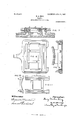
- Figure 1 is a longitudinal elevation partly in section of a simple piston slide valve constructed according to this invention and Fig. 2 is an end elevation of the same.
- Figs. 3 and 4 are similar views to Figs. 1 and 2 showing a modified construction in which the acting edges or parts are on the movable part of the valve.
- Figs. 5 and 6 are views, one showing oblong ports and the other circular ports.
- Fig. 7 is a longitudinal section of a D slide valve constructed according to this invention, and Fig. 8 is a plan of the underside of the valve, and Fig. 9 is a cross section of the same.
- Figs. 10 and 11 are end elevation and plan of the movable part of the valve.
- the valve consists of two outerheads A fixed on the operating spindle B and of the two inner heads C connected by a sleeve D adapted to slideon the spindle B between the outer heads A.
- the heads A and C of the two parts are of the same diameter and the sleeve D with its head C is made of such length that it has a motion on the spindle B of about the width of the admission ports.
- the exhaust port which had been previously closed to the right hand steam port by the right hand head C will now be open and continue so until the valve has reached the end of its stroke and has moved a certain distance in the direction reverse to the arrow the right hand heads A and C remaining in contact on the spindle.
- the valve in its motion will open the left hand port to the exhaust at the same time as the steam is admitted to the right hand port.
- the immediate effect will be that the sleeve D and heads C are moved on the spindle B and again take up the position shown with the left hand. heads A and C in contact.
- the valve consists of two heads A fixed upon the operating spindle B and of an outerpart adapted to slide on the spindle B consisting of a sleeve F with two heads E having hollow extensions G provided at each end with two sets of admission ports H I and sliding on the heads A that always close the inner ports I against live steam direct from the steam chest.
- the left hand heads A and E will remain in contact as shown until the left live steam port is opened when steam passing through the port H is admitted through the port I between the left hand head A and the left hand head E thus forcing the sleeve and.
- extension G to the right and fully opening the exhaust port while the steam admission and cut off is determined by the positively operated part, the outer edge of the extension G being new in line with the outer edge of the fixed head A and taking the place of the inner edge of the port H.
- grooves L are formed in the inside of the extensions G so as to more readily admit the steam, and on the edges of the inner valve as shown in Figs. 8 and 11. y
- the construction is as follows :
- the outer part M of the valve is positively operated by the valve spindle.
- the inner part consists of two transverse bars N connected by the ribs 0 and provided on their backs with grooves to receive the packing pieces P.
- the inner part works within the outer part and is guided by the ends of the bars sliding against the faces formed on the sides of the hollow in the part M.
- a distributing valve for fluid pressure engines consisting of a valve seat having two outer admission ports and a central ex haust port, a main positive operated valve part and a secondary valve part movable with respect to the main valve part and having the usual exhaust cavity, chambers at each end between the valve parts and communicating with ports so situated that when the valve is in position to admit steam to an admission port, said chambers open. to communicate with the admission ports.
- a distributing valve for fluid pressure engines consisting of a cylindrical valve seat having outer admission ports and a central exhaust, two main heads of less width than the width of the admission port and connected by a spindle and positively operated so that the heads cover and uncover the admission ports, a jumper consisting of two heads a connecting piece sliding between the two main heads, the cavity between the two jumper heads forming the usual exhaust cavity, the chambers between the heads being so situated that when the valve is in position to admit steam to an admission port said chambers communicate with the admission ports.
Description
No. 856,470. PATENTBD JUNE 11, 1907. H. 0. KING VALVE.
APPLICATION FILED OUT-13. 1900.
' 2 SHfiETB-SHEET 1.
L IIHI.I II III gr'lLlllll ll WEFICS O QQQ QOO O O Q Q O O H o O 6 Witnesses. Inv t BIO-856,470. PATENTED JUNE 11, 1907.
H. 0. KING.
VALVE.
APPLICATION TILED OUT. 13, 1900.
2 SHEETS-SHEET 2.
I P P "A \\OQN FIG 7 \llllllll UNITED STATES PATENT OFFICE.
HENRY CHARLES KING, OF SWINDON, ENGLAND.
VALVE.
Specification of Letters Patent.
Patented June 1 1, 1907.
Application filed October 13,1900. Serial No. 32,991.
Expansive Fluids in Engines, (for which I have made application for patent in Great Britain, No. 5,966, dated March 30, 1900;) and I do hereby declare the following to be a full, clear, and exact description of the invention, such as will enable others skilled in the art to which it appertains to make and use the same.
This invention for improvements in valves used for the distribution of expansive fluids in engines relates to reciprocating slide valves of the piston and D type and has for its object to effect the somewhat sudden and full opening of the exhaust at the end of the stroke so that the expansion can be continued to the end of the stroke and the later closing of the exhaust at the other end of the cylinder so that the compression is considerably reduced; and consists in constructing the valve in two parts, one operated positively and the other having a limited motion on the operated part and being actuated with it and is also automatically actuated from one extreme position on the operated part to the other extreme position by the initial admission of steam.
In the accompanying two sheets of drawings: Figure 1 is a longitudinal elevation partly in section of a simple piston slide valve constructed according to this invention and Fig. 2 is an end elevation of the same. Figs. 3 and 4 are similar views to Figs. 1 and 2 showing a modified construction in which the acting edges or parts are on the movable part of the valve. Figs. 5 and 6 are views, one showing oblong ports and the other circular ports. Fig. 7 is a longitudinal section of a D slide valve constructed according to this invention, and Fig. 8 is a plan of the underside of the valve, and Fig. 9 is a cross section of the same. Figs. 10 and 11 are end elevation and plan of the movable part of the valve.
Referring to Figs. 1 and 2 the valve consists of two outerheads A fixed on the operating spindle B and of the two inner heads C connected by a sleeve D adapted to slideon the spindle B between the outer heads A. The heads A and C of the two parts are of the same diameter and the sleeve D with its head C is made of such length that it has a motion on the spindle B of about the width of the admission ports. Assuming the valve to be in the position shown and to be moving in the direction of the arrow, the left hand heads A and C will remain in contact as shown until the left live steam port is opened when the sleeve D and heads C are moved on the spindle B by the live steam passing into the port' getting between the adjacent heads and separating them until the motion is arrested by the right hand heads A and C coming in contact. A uantity of steam or air is trapped between the heads which will prevent destructive impact, .a projection Z on'the fixed head and a corresponding recess in the movable head being provided to increase the cushioning effect. The exhaust port which had been previously closed to the right hand steam port by the right hand head C will now be open and continue so until the valve has reached the end of its stroke and has moved a certain distance in the direction reverse to the arrow the right hand heads A and C remaining in contact on the spindle. The valve in its motion will open the left hand port to the exhaust at the same time as the steam is admitted to the right hand port. The immediate effect will be that the sleeve D and heads C are moved on the spindle B and again take up the position shown with the left hand. heads A and C in contact.
In the modifications shown in Figs. 3 and 4 the valve consists of two heads A fixed upon the operating spindle B and of an outerpart adapted to slide on the spindle B consisting of a sleeve F with two heads E having hollow extensions G provided at each end with two sets of admission ports H I and sliding on the heads A that always close the inner ports I against live steam direct from the steam chest. Assuming the parts to be in the position shown and to be traveling in the direction of the arrow, the left hand heads A and E will remain in contact as shown until the left live steam port is opened when steam passing through the port H is admitted through the port I between the left hand head A and the left hand head E thus forcing the sleeve and. extension G to the right and fully opening the exhaust port while the steam admission and cut off is determined by the positively operated part, the outer edge of the extension G being new in line with the outer edge of the fixed head A and taking the place of the inner edge of the port H. To
ITO
facilitate the operation of the moving part as described, grooves L are formed in the inside of the extensions G so as to more readily admit the steam, and on the edges of the inner valve as shown in Figs. 8 and 11. y
In the modification shown in Figs. 7 to 11 the mode of operation is exactly as described with reference to Figs. 1 and 2. The construction is as follows :The outer part M of the valve is positively operated by the valve spindle. The inner part consists of two transverse bars N connected by the ribs 0 and provided on their backs with grooves to receive the packing pieces P. The inner part works within the outer part and is guided by the ends of the bars sliding against the faces formed on the sides of the hollow in the part M.
Having thus described my invention what I claim and desire to secure by Letters Patent is 1. A distributing valve for fluid pressure engines, consisting of a valve seat having two outer admission ports and a central ex haust port, a main positive operated valve part and a secondary valve part movable with respect to the main valve part and having the usual exhaust cavity, chambers at each end between the valve parts and communicating with ports so situated that when the valve is in position to admit steam to an admission port, said chambers open. to communicate with the admission ports.
2. A distributing valve for fluid pressure engines, consisting of a valve seat having two outer admission ports and a central exhaust port, a main body, a jumper or secondary body adapted to slide between stops on the main body and provided with the usual exhaust cavity 'and two heads or ends that make a sliding joint with the main body, and of chambers at each end between the parts and communicating with ports so situated that when the valve is in position to admit steam to an admission port said chambers communicate with the admission ports.
3. A distributing valve for fluid pressure engines, consisting of a cylindrical valve seat having outer admission ports and a central exhaust, two main heads of less width than the width of the admission port and connected by a spindle and positively operated so that the heads cover and uncover the admission ports, a jumper consisting of two heads a connecting piece sliding between the two main heads, the cavity between the two jumper heads forming the usual exhaust cavity, the chambers between the heads being so situated that when the valve is in position to admit steam to an admission port said chambers communicate with the admission ports.
In testimony whereof he has affixed his signature, in presence of two witnesses.
HENRY CHARLES KING.
Witnesses:
L. SoMERs BRADFORD, WM. AQPITCHER.
Priority Applications (1)
| Application Number | Priority Date | Filing Date | Title |
|---|---|---|---|
| US3299100A US856470A (en) | 1900-10-13 | 1900-10-13 | Valve. |
Applications Claiming Priority (1)
| Application Number | Priority Date | Filing Date | Title |
|---|---|---|---|
| US3299100A US856470A (en) | 1900-10-13 | 1900-10-13 | Valve. |
Publications (1)
| Publication Number | Publication Date |
|---|---|
| US856470A true US856470A (en) | 1907-06-11 |
Family
ID=2924925
Family Applications (1)
| Application Number | Title | Priority Date | Filing Date |
|---|---|---|---|
| US3299100A Expired - Lifetime US856470A (en) | 1900-10-13 | 1900-10-13 | Valve. |
Country Status (1)
| Country | Link |
|---|---|
| US (1) | US856470A (en) |
-
1900
- 1900-10-13 US US3299100A patent/US856470A/en not_active Expired - Lifetime
Similar Documents
| Publication | Publication Date | Title |
|---|---|---|
| US856470A (en) | Valve. | |
| US303703A (en) | carricaburu | |
| US1571560A (en) | Pneumatic tool | |
| US1082635A (en) | Water-motor. | |
| US285271A (en) | Steam-engine | |
| US1187091A (en) | Fluid-pressure engine. | |
| US907250A (en) | Hydraulic motor. | |
| US1117370A (en) | Hydraulic motor. | |
| US110490A (en) | Improvement in balanced slide-valves | |
| US944221A (en) | Water-motor. | |
| US763586A (en) | Cylinder for steam-engines. | |
| US321581A (en) | Leon b | |
| US561096A (en) | George w | |
| US1166028A (en) | Fluid-motor. | |
| US632931A (en) | Steam-actuated valve for engines. | |
| US1185139A (en) | Valve mechanism for pumps, compressors, &c. | |
| US1577914A (en) | Steam-engine valve gear | |
| US1182372A (en) | Air-compressing pump. | |
| US867774A (en) | Valve for direct-acting steam-pumps. | |
| US144831A (en) | Improvement in valve-actuating mechanisms for engines | |
| US889622A (en) | Steam-engine. | |
| US869794A (en) | Steam-actuated valve. | |
| US752401A (en) | Reversing-valve for steam-engines | |
| US175894A (en) | Improvement in balanced valves | |
| US655929A (en) | Piston-valve for engines. |