US856465A - Block-signal system. - Google Patents
Block-signal system. Download PDFInfo
- Publication number
- US856465A US856465A US34603406A US1906346034A US856465A US 856465 A US856465 A US 856465A US 34603406 A US34603406 A US 34603406A US 1906346034 A US1906346034 A US 1906346034A US 856465 A US856465 A US 856465A
- Authority
- US
- United States
- Prior art keywords
- relay
- rails
- current
- track
- sources
- Prior art date
- Legal status (The legal status is an assumption and is not a legal conclusion. Google has not performed a legal analysis and makes no representation as to the accuracy of the status listed.)
- Expired - Lifetime
Links
Images
Classifications
-
- B—PERFORMING OPERATIONS; TRANSPORTING
- B61—RAILWAYS
- B61L—GUIDING RAILWAY TRAFFIC; ENSURING THE SAFETY OF RAILWAY TRAFFIC
- B61L23/00—Control, warning, or like safety means along the route or between vehicles or vehicle trains
- B61L23/08—Control, warning, or like safety means along the route or between vehicles or vehicle trains for controlling traffic in one direction only
- B61L23/14—Control, warning, or like safety means along the route or between vehicles or vehicle trains for controlling traffic in one direction only automatically operated
- B61L23/16—Track circuits specially adapted for section blocking
- B61L23/166—Track circuits specially adapted for section blocking using alternating current
Definitions
- My invention consists in an improvement in the system described in an application, Serial No. 335,209, :tiled by l. il. Bliss, September 19, i905, goed to the General Electric C inpany. ln that application was described a block signal system forelectricallyoperated roads having both rails conductively continuous for all currents in whichsoiuees of alternating-e'urrent vwere connected across the track-rails at intervals, adjacent sources being of dille/rent phase, with track relays connectedv across the rails in pairs at points between the sources, one relay of each pair being arranged to drop its armature upon the y diagram.
- each re-lay is provided with two cooperating windings, one 'connected across the' track-rails, and consequently .supplied with the resultant current delivered by the two adj; nt sources, while the other Winding is sul il' d independently of the rails with a current which, in a relay of the induction type, corresponds in phase to that of one el' the adjacent sources.
- My invention ccnsistsi arranging a single relay so as to take 'the pif ⁇ e of the pair of re# lays described in the torn r application.
- D represents a three-phase high-frequency generator, which supplies the signal-current for the rail-circuits through the transmissionlines d, extending alongl the track.
- El, E2, etc. represent transformers, the pri-- maries ol: which are connccled to the trans mission-lines d, and the secondari-ies ol' which are connected across the track rails. lt will be seen that adjacent transformers are connected to dillorcnt phases ol the transmission lines d.
- Sinall resistanccs e may be inserted in series with the secondaries ol' the transformers to reduce the llow of power-current through the transferium windings il the track bonding becomes defective.
- F1 and F2 represent relays each having; two coperating windings; one connectcl'l across the track-rails, and the other supplied with alternatingcurrent independently ol' the rails.
- relays ol' the Well-known induction type each comprising,r a short-circuited secondaryfcarrying the relay contact, and two primary windings fl and f", the lirst vof which is corniected across the rails through a resistance f to reduce the flow of power-current through the winding, while the other is connected directly to the l e. linefwires d or otherwise supplied with. cunl o in tlie circuit ol the windingj"-' to supply the desired adjustment. As long; as track between two adjacent transformers is clear,
- the relay connected to the track between them will consequently have pl1asedisplacement of ninety degrees of the currents in the windings, thcrby producing an cllective torque, so as to maintain its contact closed.
- This is shown in the case ol" relay F, controlling the signal G?. lf, however', one of the transformers is cut pil' l'rorn the relay by a broken rail, or is shrt-circuited by'a train, as shown at H in the drawing, the relay torque will fall to ifty per cent.
- o c1 represents the currents in the rails, due tothe voltage 0 el. AThis 'current lags behind the voltage by a large angle due to the high inductance of the rail-circuit with the high frequency that is preferablyv employed for the system. Similarly, o c2, 120 degrees out of phase with 0 c', represents the current in the rails due to the voltage 0 e2,
- o f2 represents the current which is supplied to the second winding of the relay, displaced ninety degrees from o f1.
Description
@an PATENTED JUNE 11, 1907. L. A. HAWKINS. BLOCK SIGNAL SYSTEM.
AYPLIDATIOH FILED 33110.3,1006- Inventor Laurence A Hawmns..
Utllfllill) STATES PATENT #@EFllflfiit LAURENCE A. ,HAWKlNS, OF SCHENEClADY, NllW YUlll, rlSSftlll'Olt T() l GENERAL lill-llUlltlC COMPANY, A CORPORATION OF NEW YOl-tli,
SLGCKPSlGaNAL SYSTEWL Specification of Letters Patent.
Patented J une 1 l, 1907.
To ill whom' it may concelt:
-Be it known that l, LAURENCE A. HAW- KINS, a citizen of the United States, residing at Schenectady, county of Schenectady, State oi New York, have invented certain new and useful linpro venients in Block-Signal Systems, of which the following is a spec1- ication.
My invention consists in an improvement in the system described in an application, Serial No. 335,209, :tiled by l. il. Bliss, September 19, i905, goed to the General Electric C inpany. ln that application was described a block signal system forelectricallyoperated roads having both rails conductively continuous for all currents in whichsoiuees of alternating-e'urrent vwere connected across the track-rails at intervals, adjacent sources being of dille/rent phase, with track relays connectedv across the rails in pairs at points between the sources, one relay of each pair being arranged to drop its armature upon the y diagram.
failure ci one oi the two adjacent sources. For this purpose, each re-lay, is provided with two cooperating windings, one 'connected across the' track-rails, and consequently .supplied with the resultant current delivered by the two adj; nt sources, while the other Winding is sul il' d independently of the rails with a current which, in a relay of the induction type, corresponds in phase to that of one el' the adjacent sources. With this arraninent, upon the fallu of either source, t torque of one relay falls to Zoro, `while the torque ol the other relay remains normal. By connecting the contacts ol the two relays in series, the signal controlled by them. is put at danger by the failure of either source.
My invention ccnsistsi arranging a single relay so as to take 'the pif` e of the pair of re# lays described in the torn r application.
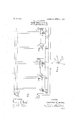
My invention will best be. understood `by reference to the acconipcnying drawings, in which Figure l sl "evs diagra:nznatically a block signal systein ari need in accordance with my invention lelie; is an explanatory In Fig. l, A represents the track-rails, which may be condueuvely continuous for all currents throupfhout their length, B represents the thirdor other conductor of power-current, which is connected to one terminal ol the powt` genera-tor C; the other terminal of which is connected to the trackrails through the differential choke-coil c. This generator' may produce direc lz-current or low-frequencyalternating-c1u'reut. j
D represents a three-phase high-frequency generator, which supplies the signal-current for the rail-circuits through the transmissionlines d, extending alongl the track.
El, E2, etc., represent transformers, the pri-- maries ol: which are connccled to the trans mission-lines d, and the secondari-ies ol' which are connected across the track rails. lt will be seen that adjacent transformers are connected to dillorcnt phases ol the transmission lines d. Sinall resistanccs e may be inserted in series with the secondaries ol' the transformers to reduce the llow of power-current through the transferium windings il the track bonding becomes defective.
F1 and F2 represent relays each having; two coperating windings; one connectcl'l across the track-rails, and the other supplied with alternatingcurrent independently ol' the rails.
In the drawing l. have shown relays ol' the Well-known induction type each comprising,r a short-circuited secondaryfcarrying the relay contact, and two primary windings fl and f", the lirst vof which is corniected across the rails through a resistance f to reduce the flow of power-current through the winding, while the other is connected directly to the l e. linefwires d or otherwise supplied with. cunl o in tlie circuit ol the windingj"-' to supply the desired adjustment. As long; as track between two adjacent transformers is clear,
the relay connected to the track between them will consequently have pl1asedisplacement of ninety degrees of the currents in the windings, thcrby producing an cllective torque, so as to maintain its contact closed. This is shown in the case ol" relay F, controlling the signal G?. lf, however', one of the transformers is cut pil' l'rorn the relay by a broken rail, or is shrt-circuited by'a train, as shown at H in the drawing, the relay torque will fall to ifty per cent. of its normal value, or less, if the `presence of the train at H reduces the amount of current supplied to the winding f1 by the transformer By adjusting the relay so that it lwill drop its armature when the torque vfalls to fifty per cent. of normal, the relay F1 will have dropped its armature when the train passes the transformer E! thereby putting the signal at danger indicating that the block is occupied.
The phase relations of the currents in the relay windings, and the effect of short-circuiting one adjacent transformer will be readily understood by an inspection of Fig. 2, in whichv 0 c1 represents the voltage impressed on the rails by the transformer El, and`0 e2, 120 degrees out of phase with o e', the voltage impressed on the rails by the transformer E2.
o c1 represents the currents in the rails, due tothe voltage 0 el. AThis 'current lags behind the voltage by a large angle due to the high inductance of the rail-circuit with the high frequency that is preferablyv employed for the system. Similarly, o c2, 120 degrees out of phase with 0 c', represents the current in the rails due to the voltage 0 e2,
0j", 60 degrees out of phase with both o c/ and o c?, consequently represents the resultant current which flows through the track winding of the relay.
o f2 represents the current which is supplied to the second winding of the relay, displaced ninety degrees from o f1. Y
v The torque produced in a relay'of the induction type, ,is proportional to the product of the currents in the two windings multiplied by the sine of the phase-angle between them, which is 'normally ninetyvv degrees, as shown in Fig; 2. ,i
Now, if either transformer fails, one of the component currents, as for instance, o c1 will disappear, and the current through the track winding of the relay will consequently be the current supplied by the other transformer, o c2. The torque of the relay remains proportional to the product of the currents multiplied by the sine of the phase-angle between them. The amounts of the currents have remainedl unchanged, bult the phaseangle has shil'led from ninety degrees to thirty, and since the sine of ninety degreesis l, and the sine. of 3() degrees 'is 9;, the relay torque has fallen to one half its normal value. lf a train short-circuiting one transformer somewhat reduces the current supplied to the track winding of the relay by the other transformer, the relay torque will fall to lessthan fifty per cent. of normal. Consequently, by vadjusting the relay so as to drop its armature at fifty per cent. of normal torque, the relay will at all times put the signal at danger upon the failure of either adja cent transformer, whether because of a broken rail or because of the presence of a train in the block. 1What claim as new and desire to secure by Letters Patent of the United States, is:
l. In combination with an electric railway having` both rails conductively' continuous for all currents, sources of alternating-current connected across the rails at intervals, adjacent sources being of dilllerent phase, and signal controlling relays connected singly across the rails between the sources, each relay being responsive to control a signal onlywhen supplied with current from both adjacent sources.
2. ln combination with an electric railway having both rails conductively continuous for all currents, sources of alternatingnurrent connected across the rails at intervals, adjacent sources being of lditl'erent phase, and signal controlling rela-ys connected singly across the rails between the sources,
'each relay having two cooperating windings,
one copnected across the track-rails and the other supplied ,independently of the rails with alternating-current of proper phase for effectively operating the relay only when the track winding is traversed by a current corresponding in phase to the resultant current delivered by the two adj acent sources.
3. In combination with an electric railway' having bothrails conductively. continuous for all currents, sources of alternating-current connected across the rails at intervals, adjacent sources being etoilferent phase, and signal controlling relays connected" singly across the rails between the sources, each relay comprising a short-circuited secondary memberl and two primary windings, one connected across the' track-rails and the other supplied independently of the rails with current substantially ninety degrees out of phase with the resultant current de* li vered by the two adj aeent sources.
IGS
In witness whereof, have hereunto .set
my hand this 30th day of November, 1906.
LAURENCE A. HAWKlQNS.
Vitnesses:
.BENJAMIN HULL,
MARGARET E. Noorman
Priority Applications (1)
| Application Number | Priority Date | Filing Date | Title |
|---|---|---|---|
| US34603406A US856465A (en) | 1906-12-03 | 1906-12-03 | Block-signal system. |
Applications Claiming Priority (1)
| Application Number | Priority Date | Filing Date | Title |
|---|---|---|---|
| US34603406A US856465A (en) | 1906-12-03 | 1906-12-03 | Block-signal system. |
Publications (1)
| Publication Number | Publication Date |
|---|---|
| US856465A true US856465A (en) | 1907-06-11 |
Family
ID=2924920
Family Applications (1)
| Application Number | Title | Priority Date | Filing Date |
|---|---|---|---|
| US34603406A Expired - Lifetime US856465A (en) | 1906-12-03 | 1906-12-03 | Block-signal system. |
Country Status (1)
| Country | Link |
|---|---|
| US (1) | US856465A (en) |
Cited By (2)
| Publication number | Priority date | Publication date | Assignee | Title |
|---|---|---|---|---|
| US2930888A (en) * | 1956-03-05 | 1960-03-29 | Archibald M Crawford | Coupling speed control device |
| US8269374B2 (en) | 2010-03-04 | 2012-09-18 | De Caires Damian | Solar panel power management system and method |
-
1906
- 1906-12-03 US US34603406A patent/US856465A/en not_active Expired - Lifetime
Cited By (2)
| Publication number | Priority date | Publication date | Assignee | Title |
|---|---|---|---|---|
| US2930888A (en) * | 1956-03-05 | 1960-03-29 | Archibald M Crawford | Coupling speed control device |
| US8269374B2 (en) | 2010-03-04 | 2012-09-18 | De Caires Damian | Solar panel power management system and method |
Similar Documents
| Publication | Publication Date | Title |
|---|---|---|
| US856465A (en) | Block-signal system. | |
| US1094894A (en) | Block-signal system. | |
| US531432A (en) | Cueeeni motors | |
| US900370A (en) | Block-signaling system. | |
| US861015A (en) | Block-signal system. | |
| US1181576A (en) | Broken-down-insulating-joint protection. | |
| US1081925A (en) | Railway signaling system. | |
| US1188272A (en) | Block-signal system. | |
| US929591A (en) | Block-signal system. | |
| US1528505A (en) | Railway-traffic-controlling apparatus | |
| US1576944A (en) | Railway-traffic-controlling apparatus | |
| US897524A (en) | Block-signal system. | |
| US1091133A (en) | Block-signal system. | |
| US1094103A (en) | Automatic block-signaling system for electric railways. | |
| US869365A (en) | Block-signal system. | |
| US1056993A (en) | Alternating-current track-circuit signaling. | |
| US1296095A (en) | Railway signaling. | |
| US859219A (en) | Block-signal system. | |
| US1396825A (en) | Railway signaling system | |
| US1128057A (en) | Block-signal system for electric railways. | |
| US1188273A (en) | Block-signal system. | |
| US1608021A (en) | Railway-traffic-controlling apparatus | |
| US964710A (en) | Electric signaling system. | |
| US856440A (en) | Block-signal system. | |
| US856466A (en) | Block-signal system. |