US856461A - Railway-brake. - Google Patents
Railway-brake. Download PDFInfo
- Publication number
- US856461A US856461A US36300207A US1907363002A US856461A US 856461 A US856461 A US 856461A US 36300207 A US36300207 A US 36300207A US 1907363002 A US1907363002 A US 1907363002A US 856461 A US856461 A US 856461A
- Authority
- US
- United States
- Prior art keywords
- brake
- shoe
- links
- bracket
- head
- Prior art date
- Legal status (The legal status is an assumption and is not a legal conclusion. Google has not performed a legal analysis and makes no representation as to the accuracy of the status listed.)
- Expired - Lifetime
Links
Images
Classifications
-
- F—MECHANICAL ENGINEERING; LIGHTING; HEATING; WEAPONS; BLASTING
- F16—ENGINEERING ELEMENTS AND UNITS; GENERAL MEASURES FOR PRODUCING AND MAINTAINING EFFECTIVE FUNCTIONING OF MACHINES OR INSTALLATIONS; THERMAL INSULATION IN GENERAL
- F16D—COUPLINGS FOR TRANSMITTING ROTATION; CLUTCHES; BRAKES
- F16D65/00—Parts or details
- F16D65/02—Braking members; Mounting thereof
- F16D65/04—Bands, shoes or pads; Pivots or supporting members therefor
- F16D65/06—Bands, shoes or pads; Pivots or supporting members therefor for externally-engaging brakes
- F16D65/062—Bands, shoes or pads; Pivots or supporting members therefor for externally-engaging brakes engaging the tread of a railway wheel
Definitions
- This invention relates to railway brakes, and its objects are to prevent the rattling and wear of parts and hence to prolong their life, to afford the brake lever the greatest possible throw within limited space, and to balance the brake head and shoe and aline it with the wheel.
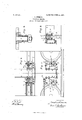
- Figure 1 is a side view with the forward bar of the truck frame removed and the transoms in section.
- Fig. 2 is a plan view.
- Fig. 3 is an edge view with the bracket in section.
- Fig. 4 is an enlarged sectional detail of one bolt and its friction spring.
- j are the brake'rods pivoted at n to one lever and whose operation is well understood.
- I make these rods round and spaced so as to span the wheel, and their ends are bent toward each other and reinforced to give them strength where the pivot n occurs.
- the brake levers swing between the transoms and wheels, and one object of this invention is to give them the greatest possible throw in this space, more especially because on the trucks of electric cars the motors stand between the wheels.
- the present invention consists in the form of hanger bracket used in connection with the above parts and the anti-rattler springs employed at the ends of the links by which the shoe head is supported, as now to be described.
- the letters i designate the hanger brackets which are of forged mild steel and made in pairsonc right hand the other left hand.
- the bodies of the members of each pair are parallel and their feet are shown as bolted. to the transoms a,-though the construction may be varied to accommodate trucks of different type. But it is desirable that these brackets project from the transoms toward the wheels and as close as may be to them and that the members of each pair be spaced so as to form a guide for the inclosed lever d which can swing from its outer position against the transom inward for the full length of the brackets.
- the operation of the device will be obvious to those skilled in the art.
- the constant tendency of the springs Z is to bind the links h against the outer sides of the brackets and of the head with suflicient friction to prevent rattle and hence to prevent wear occasioned by excessive looseness.
- the shape and position of the brackets provides a guide for the lever while yet giving it the greatest possible throw in the limited space existing.
- the position of the through bolt is within the head f is such that the head and shoe are balanced so that (with the aid of the spring-pressed links) the shoe remains in parallelism with the face'of the wheel.
- a bracket comprising ,two members with parallel bodies and outturned feet, the latter bolted to said transom, the brake lever guided between said bodies and connected with the shoe, the spreader, links pivotally connecting the bracket and shoe, and anti-rattling springs on the pivots of the links.
- a bracket comprising two parallel members supported by the transom, the brake lever guided between them and connected with the shoe, the spreader, links on the outer sides of the bracket and shoe, a bolt through the latter and the lower ends of the'links, a bolt having its head countersunk in each bracket member and its body projecting through the upper end of one link, and anti-rattling springs on the bolts next outside both ends of each link.
- the combi nation with the wheel, the brake head and its connected parts, and the brake lever; of a bracket, links pivotally connecting the bracket and head and standing on their outer faces, and springs on all the pivots of the links holding them in frictional contact with the bracket and head and tending to maintain the latter on its center of gravity with its shoe parallel to the face of the wheel.
Description
PATENTED JUNE 11, 1907.
0. PURM'AN. RAILWAY BRAKE.
APPLIGATIONI'ILBD MAR.18, 1907.
INVENTOR:
A TTURNE).
Tut NORRIS PETERS cc, WASHINGTON, n. c.
UNITED STATES CORNELIUS FURMAN, OF DECATUR, ILLINOIS.
RAILWAY-BRAKE.
Specification of Letters Patent.
Patented June 11, 1907.
Application filed March 18,1907. Serial No. 363.002.
To all whom it may concern;
Be it known that I, CORNELIUS FURMAN, a citizen of the United States, and a resident of Decatur, in the county of Macon and State of Illinois, have invented certain new and useful Improvements in Railway-Brakes, and my preferred manner of carrying out the invention is set forth in the following full, clear, and exact description, terminating with claims particularly specifying the novelty.
This invention relates to railway brakes, and its objects are to prevent the rattling and wear of parts and hence to prolong their life, to afford the brake lever the greatest possible throw within limited space, and to balance the brake head and shoe and aline it with the wheel.
These objects I accomplish by the following construction which embodies perhaps the most satisfactory design in behalf of workmanship, but it will be understood that I do not limit myself strictly thereto as the gist of the invention is set forth in the claims below.
In the accompanying drawings forming part of this specification Figure 1 is a side view with the forward bar of the truck frame removed and the transoms in section. Fig. 2 is a plan view. Fig. 3 is an edge view with the bracket in section. Fig. 4 is an enlarged sectional detail of one bolt and its friction spring.
In the drawings it represents the transom bars connecting the side frames 1) of which only one is shown, and c are wheels.
(1 are the brake levers having a spreader a between their lower ends, here shown as a turn buckle.
j are the brake'rods pivoted at n to one lever and whose operation is well understood. By preference I make these rods round and spaced so as to span the wheel, and their ends are bent toward each other and reinforced to give them strength where the pivot n occurs. The brake levers swing between the transoms and wheels, and one object of this invention is to give them the greatest possible throw in this space, more especially because on the trucks of electric cars the motors stand between the wheels.
is the brake shoe mounted on the shoe head f, and the latter is pivoted to the lever d as at m.
More particularly the present invention consists in the form of hanger bracket used in connection with the above parts and the anti-rattler springs employed at the ends of the links by which the shoe head is supported, as now to be described.
The letters i designate the hanger brackets which are of forged mild steel and made in pairsonc right hand the other left hand. The bodies of the members of each pair are parallel and their feet are shown as bolted. to the transoms a,-though the construction may be varied to accommodate trucks of different type. But it is desirable that these brackets project from the transoms toward the wheels and as close as may be to them and that the members of each pair be spaced so as to form a guide for the inclosed lever d which can swing from its outer position against the transom inward for the full length of the brackets.
is are bolts whose heads are countersunk in the brackets as shown in Fig. 4 and whose bodies project outward therefrom, and on them next the brackets are hung links it, expansive springs Z being coiled on the bolts between their nuts and said links to prevent rattling of parts. The lower ends of the links it, are connected by a through bolt which passes through the link and the shoe head f, and outside said links other anti-rattling springs Z are also employed. The pivotal point of the bolt 71' within the head f is such that the shoe and its head and connected parts are balanced and held so by the springs Z pressing the links it against the head Hence when the brake is released from the wheel the shoe will retain its proper position with relation to the face of the wheel. Countersinking the heads of bolts It prevents the striking of lever (Z against them.
The operation of the device will be obvious to those skilled in the art. The constant tendency of the springs Z is to bind the links h against the outer sides of the brackets and of the head with suflicient friction to prevent rattle and hence to prevent wear occasioned by excessive looseness. The shape and position of the brackets provides a guide for the lever while yet giving it the greatest possible throw in the limited space existing. And the position of the through bolt is within the head f is such that the head and shoe are balanced so that (with the aid of the spring-pressed links) the shoe remains in parallelism with the face'of the wheel.
What is claimed as new is:
1. In a railway truck brake, the combination with the wheel, the shoe, and the transom; of a bracket comprising ,two members with parallel bodies and outturned feet, the latter bolted to said transom, the brake lever guided between said bodies and connected with the shoe, the spreader, links pivotally connecting the bracket and shoe, and anti-rattling springs on the pivots of the links.
2. In a railway truck brake, the combination with the wheel, the shoe, and the transomj of a bracket comprising two parallel members supported by the transom, the brake lever guided between them and connected with the shoe, the spreader, links on the outer sides of the bracket and shoe, a bolt through the latter and the lower ends of the'links, a bolt having its head countersunk in each bracket member and its body projecting through the upper end of one link, and anti-rattling springs on the bolts next outside both ends of each link.
3. In a railway truck brake, the combination with the wheel, the shoe, and the transom; of a bracket comprising two parallel members supported by the transom, the brake lever guided between them and connected with the shoe, the spreader, and links pivotally connecting the bracket and shoe and supporting the latter and connected parts on their center of gravity.
4. In a railway truck brake, the combination with the wheel, the shoe, the brake lever connected thereto, and the spreader; of brake rods spanning the wheel and connected to the lever, a bracket comprising parallel members forming a guide for the lever, and links connecting the bracket and shoe.
5. In the railway truck brake, the combi nation with the wheel, the brake head and its connected parts, and the brake lever; of a bracket, links pivotally connecting the bracket and head and standing on their outer faces, and springs on all the pivots of the links holding them in frictional contact with the bracket and head and tending to maintain the latter on its center of gravity with its shoe parallel to the face of the wheel.
In testimony whereof I have hereunto subscribed my signature this the 14th day of March A. D. 1907.
CORNELIUS FURMAN.
Witnesses:
FELIX B. TAIT, EDWARD C. BASSEY.
Priority Applications (1)
| Application Number | Priority Date | Filing Date | Title |
|---|---|---|---|
| US36300207A US856461A (en) | 1907-03-18 | 1907-03-18 | Railway-brake. |
Applications Claiming Priority (1)
| Application Number | Priority Date | Filing Date | Title |
|---|---|---|---|
| US36300207A US856461A (en) | 1907-03-18 | 1907-03-18 | Railway-brake. |
Publications (1)
| Publication Number | Publication Date |
|---|---|
| US856461A true US856461A (en) | 1907-06-11 |
Family
ID=2924916
Family Applications (1)
| Application Number | Title | Priority Date | Filing Date |
|---|---|---|---|
| US36300207A Expired - Lifetime US856461A (en) | 1907-03-18 | 1907-03-18 | Railway-brake. |
Country Status (1)
| Country | Link |
|---|---|
| US (1) | US856461A (en) |
-
1907
- 1907-03-18 US US36300207A patent/US856461A/en not_active Expired - Lifetime
Similar Documents
| Publication | Publication Date | Title |
|---|---|---|
| US856461A (en) | Railway-brake. | |
| US551700A (en) | Combined car brake and fender | |
| US960425A (en) | Brake. | |
| US511973A (en) | John fred stevens | |
| US1138430A (en) | Non-chattering brake-hanger. | |
| US554359A (en) | breed | |
| US116814A (en) | Improvement in automatic car-brakes | |
| US4886A (en) | Brake fob | |
| US854449A (en) | Brake mechanism for pivoted car-trucks. | |
| US348741A (en) | Car-truck | |
| US674824A (en) | Brake for railway-cars. | |
| US792777A (en) | Wagon attachment. | |
| US572802A (en) | Car-brake | |
| US1303069A (en) | Brake hanger | |
| US128277A (en) | Improvement in car-brakes | |
| US1166521A (en) | Brake-hanger. | |
| US134934A (en) | Improvement in car-brakes | |
| US270254A (en) | Wagon platform-gearing | |
| US698310A (en) | Brake for railway-cars. | |
| US270732A (en) | Car-brake | |
| US115797A (en) | Improvement in wagons | |
| US300051A (en) | Albeet davis | |
| US303981A (en) | David buckler and edward nicholas pelzer | |
| US296113A (en) | Vehicle-spring | |
| US1025233A (en) | Spring for vehicles. |