US856440A - Block-signal system. - Google Patents
Block-signal system. Download PDFInfo
- Publication number
- US856440A US856440A US34642206A US1906346422A US856440A US 856440 A US856440 A US 856440A US 34642206 A US34642206 A US 34642206A US 1906346422 A US1906346422 A US 1906346422A US 856440 A US856440 A US 856440A
- Authority
- US
- United States
- Prior art keywords
- rails
- transformers
- current
- signal
- train
- Prior art date
- Legal status (The legal status is an assumption and is not a legal conclusion. Google has not performed a legal analysis and makes no representation as to the accuracy of the status listed.)
- Expired - Lifetime
Links
Images
Classifications
-
- B—PERFORMING OPERATIONS; TRANSPORTING
- B61—RAILWAYS
- B61L—GUIDING RAILWAY TRAFFIC; ENSURING THE SAFETY OF RAILWAY TRAFFIC
- B61L23/00—Control, warning, or like safety means along the route or between vehicles or vehicle trains
- B61L23/08—Control, warning, or like safety means along the route or between vehicles or vehicle trains for controlling traffic in one direction only
- B61L23/14—Control, warning, or like safety means along the route or between vehicles or vehicle trains for controlling traffic in one direction only automatically operated
- B61L23/16—Track circuits specially adapted for section blocking
- B61L23/166—Track circuits specially adapted for section blocking using alternating current
Definitions
- My invention relates to block signal sys ten-isfor electrically-operated roads in which 1.0 rails are employed as return conductor for the power-current.
- My invention in one aspect, consists in an improvement in the system described in a former application filed'by me September 19,
- I 5 1906, Serial N o. 355,209 in which I described a signal system in which the rails are conductively continuous for all currents, and transformers of different phase are connected across the rails at intervals, with trackre zo lay-s at points between the transformers arranged to respond only to an alternating-currentof a certain phase.
- the current-supplied. by one 2 5 transformer isprevented from actuating a .relay which it is not intended to actuate, without the use of inductive bonds or other devices for'separating adjacent blocks.
- the leakage current, from'each transformer to other blocks than that which it is not intended to supply, is 1 comparatively small, and the point at which a train shunts a track-relay is made 3 5' sufliciently definite for pra'citical purposes.
- a definite shunting point is further assured by arranging the transformers at the ends of each block and the relay in the center.
- the object of my invention is to increase 40 the, efficiency of thesystem described in my former application, while maintaining all its advantages.” I accomplish this result byaar- .rangin the transformers with normallyopen circuits and providing means controlled by; a moving train for closing the circuits of a lurality of transformers ahead of the train.
- Anot er feature ofmyinvention consists inthe arrangement of the devices for closing the circuits of the transformers ahead of the train, whereby a plurality of transformers vention.
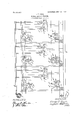
- A represents the trackrails, which are made conductively continuous throughout their length.
- the generator C may produce direct current or alternating-current of low frequency.
- ' D represents a high-frequency three-phase generator, which is connected to the transmission-wires d, from which the signal-currents are supplied to the track-rails through transformers E, E E etc. These transformers have their primaries connected to the line-wires d; adjacent transformers being connected to different phases. The transformer secondaries are connec'tedacross the track-rails. Either the primary or secondary winding of each transformenis nordesigned to respond to alternating-current of-a certain hase only. I have shown dia-. grammatical y relays of the induction type,
- d iiferkin'f ether :cheracters if preferred; such as .-i nfrequency, 1 li u'rth'ermere elthet gh iI' aheye" shown track instruments er -closings 1 the; circuits "of the .inagnetsicpntrclfingi the transfermer-cireuits, any ether arrangement, wherebyg; ineving'trein- 1s; enabled to close faj circuit,, may-"be; employed ⁇ in placcj vof -the H -jis put-fet denger,fwhile, when ,the train ,7
- signals normally -"at dan er, and signal-controllin devices connecter across the reds between ad acent sources and-operative to'close a signal only when supplied. with current.
- a transnussion system comprising more than two conductors extending along the way, means for impressing voltages differing in character upon diflerent pairs of said conductors, normally open-circuited transformers having thc1r primaries connected'to salcl system and their secondaries connected at intervals across the rails, adja cent transformers having their primaries connected across different pairs of conductors, means controlled by a moving train for closing the circuits of a plurality of transformers ahead of thetrain, signals normally at danger, and signal-controlling devices connected across the rails at points between the trans formers and operative to clear a signal only when supplied with current from bothadjacent transformers.
Description
No. 856,440. PATENTED JUNE 11, 1907 B. F. BLISS. BLOCK SIGNAL SYSTEM.
APPLICATION FILED DBO. 5,1906.
UNITED STATES PATENT OFFICE.
ELMER F. BLISS, OE SOHENEOTADY, NEW YORK, ASSIGNOR TO GENERAL ELECTRIC COMPANY, A CORPORATION OF NEW YORK.
BLOCK-SIGNAL SYSTEM.
' Specification of Letters Patent.
Patented June 11, 1907.
Application filed December 5, 1906. Serial No. 346,422.
5 York, have invented certain new and useful Improvements in Block- Signal Systems, of which .the following is a specification.
My invention relates to block signal sys ten-isfor electrically-operated roads in which 1.0 rails are employed as return conductor for the power-current.
' My invention, in one aspect, consists in an improvement in the system described in a former application filed'by me September 19,
I 5 1906, Serial N o. 355,209, in which I described a signal system in which the rails are conductively continuous for all currents, and transformers of different phase are connected across the rails at intervals, with trackre zo lay-s at points between the transformers arranged to respond only to an alternating-currentof a certain phase. By sup lying-currents of different phase throng adjacent transformers, the current-supplied. by one 2 5 transformer isprevented from actuating a .relay which it is not intended to actuate, without the use of inductive bonds or other devices for'separating adjacent blocks. By using current of high frequency, to which the rails offer a high impedance, the leakage=current, from'each transformer to other blocks than that which it is not intended to supply, is 1 comparatively small, and the point at which a train shunts a track-relay is made 3 5' sufliciently definite for pra'citical purposes. A definite shunting point is further assured by arranging the transformers at the ends of each block and the relay in the center. p
The object of my invention is to increase 40 the, efficiency of thesystem described in my former application, while maintaining all its advantages." I accomplish this result byaar- .rangin the transformers with normallyopen circuits and providing means controlled by; a moving train for closing the circuits of a lurality of transformers ahead of the train.
hus, as far as the transformer circuits are concerned, the operation is precisely the same as in the system described'in my former ap- 5 plication, while .the rest of, the transformers are opencircuited and consequently are;
wastin no current.
Anot er feature ofmyinvention consists inthe arrangement of the devices for closing the circuits of the transformers ahead of the train, whereby a plurality of transformers vention. In the drawing A represents the trackrails, which are made conductively continuous throughout their length.
B represents the third-rail, or other supply conductor, which is connected to one terminal of the power-generator O, the other terminal of which may be connected to the rails A through the differential choke-coil c. The generator C may produce direct current or alternating-current of low frequency.
' D represents a high-frequency three-phase generator, which is connected to the transmission-wires d, from which the signal-currents are supplied to the track-rails through transformers E, E E etc. These transformers have their primaries connected to the line-wires d; adjacent transformers being connected to different phases. The transformer secondaries are connec'tedacross the track-rails. Either the primary or secondary winding of each transformenis nordesigned to respond to alternating-current of-a certain hase only. I have shown dia-. grammatical y relays of the induction type,
- each comprising a short-circuited secondary member f, carrying the relay contacts, and two cooperating windings f and f, the first of which is connected across the rails, and the other of which is supplied with alternating-current independently of the trackrails. t will be seen that when two adjacent transformers, as for instance, transformers E and E have their secondary circuits closed, the track-windings of therelays F and F will be traverse y .a current corresponding to the resultant of the currents supplied tothe rails by'the two transform- 1 ers; w 'e, if either transformer should be cut off om the relays, either by being shortcorrespond inphase: ltegthet'i-fof t e.. .eth' er home. signal H};
v v Irepresent's the sonrfce ef'current'fer the r smitahle sonr'cesvof current L L etc. Fer
ccntrelling these'distant signals the home I '55: v -ent---pha.se;;=the r-currents Inaybemadextb and 'the 'resifs tances ltfl {R ete, inchided sqenergiZed; err-theiiiiagiietz'lviipulle np ere supplied with-current of 'sli eheflphese. that 1,; Ftrack'instrumentsl contrclling contact -';1nejn'1'-v 4o a x p I ,The direction of trafiic is asshowr by the tireuiwd bya train',:ior yti'bmken r511, the 1 current. through; the relay'winding's. would trensf-Qr'mer I a'lenel I The relay f when bQthI iHdmgs? f f'aire traversed by the resultant current frernfl the: twez nedj acent transformers bot-hrelaysproduce-torque and former-is cut off frernfithejrelays'fene .ofthe and 1 .Wi1l :open. its centa lcts. This arrange-' ment 'ef-f the'frdays end-"their eperaticn is fully described'in .ferrner "9;pp1ica,tie'n above referred to: 7 The contacts ef both re Jays-F? and. F are inciuded in series in the fcircuitjef' the -operating mechanism G? of the operatin' j'mechanism.
1K "',"etc.,'r?-present is a t Signals-- which are revide'dwith operating nit-3011311.-
isms J ens J ,iwhicjh are supplied frem any signalsare provided with eOn-tactsh', k in the usual manner. v M M etc-.," re resent magnets,- which, when energized, e ose" the circuits .of' the transformers E E ,"etc.-, respectiveTy. Each of 'these magnets is provided with: two ar-i v.--her s t ,-'t etc.
arrow. lqen ially all the circuits are open; and. the signals stand: at danger, 'asg'shewn-y F -but when the train reaches j; a track 'instru ment, as, for instance, T moves it m' or'nenf tarily' into the position-shown in d'ottedi inesg thereby eper'iihgthefeircnit of the cendiictor;
' '1' sind cennecting theljper tibnbf the 'eeiidu'ctoli battery. 02-. T
the bend-litter, 1 ere; sc" repmiqned that'- 'three'e-?mdgnits...M?,- M vmi n h i n t I ,1 shown, he" momentarily energizedfrom a- 6d its armatu jrejits up eiiermature' .m.. eloses e maintaining circuit or thew'megnet: M which :niey be 'treced. frofm; thefnpperl terminalhf battery 0 thrbegh the track estimate- 1;
through anneturem; magnet M 'te the-up .per r'ai1A,"imd thence to'the'lewenterminal'ef the h atteryOi- At thegsafme time the arm'ae i-r;
ture connects? the'fl upbeif'termirial cf:
1' the transformer eci'e ss; the rails. .j Sinai-I- la'riy each magnet, vwhen it is energizegt bye- .niomentary currentflew;- closes e maintain-L .ing circuit for itslfl an'dclesesjthe'cireuit'of the adjacent transferme'r'. 'NOW, ,l'et'i-the "as;
sinned-that magnets M MrtndM haye been energized in the1.man'ne11]that.has1just,beendescribed. Then an three transformers, E? "E and E have their circuits.cTese ],;-energiz ing relays F F, and F", previdednotrefin [is between'the transformers E ahd E .or hetweentransformers E and ll? Unde'rthese circumstances home." signals and 11 will be cleared; thereby closing theieircuit Of the operating. nech'enis'nrz l 0i distant signai" K? throughv the-contact hpf signal H; end cen-v distant signalsH end K ere cleare'dehead of the approaching train,- indicating that two 7 blocks ahead; ere-clear; If, however, aftrain fis in'the hlock between transfermersE 'and E then oneor both of relays F; F, willn'etpick-up its armature, so that neithersignal" H or K Will-clean Consequently, an ;-ap' proaching tr ain will be informed thatthe block ehead'is clear, but thenext block is ec- ,enpied; If ittrainis between transferm'ers E and E then One or both Ofrelays'F? and F -wi1l fail" to 'ick up its armature; so that 5 neither signal 13 119; K wiilclear. If signal 5 H2401 if signals H Tend K are cleered they remain cleabfuntil the. l train :comes close enqngh to' transformer E *tp'. pull' down its fvolta'ge sje as tQfdenergizeene-of the rela; F 01' F otelsefluntiithe trainfreaches t '2 trick instrument- T5; when :thejtrack 1118131115 rnentis metedte the'pesiticn shown in jdct- -'tedilines;breekmgthe maintaining circuit of mfigfletM? an consequently opening the circuit pfztrt'nsfe merfE In either case; when 'eitherj relay F391" F is dene'rgized the, signal aches the track instrument; ,the magnet M? is' deenergi ed, and at, the 'saine-time-the hat 1 tery 0 is connected mpmentarfily to the mag"- nets M andMi ashals been explained;
d iiferkin'f ether :cheracters, if preferred; such as .-i nfrequency, 1 li u'rth'ermere elthet gh iI' aheye" shown track instruments er -closings 1 the; circuits "of the .inagnetsicpntrclfingi the transfermer-cireuits, any ether arrangement, wherebyg; ineving'trein- 1s; enabled to close faj circuit,, may-"be; employed {in placcj vof -the H -jis put-fet denger,fwhile, when ,the train ,7
; track-instrument's. :It' 'wil'l'be noted theflif; ,7 due t etenripereturevariations or ethe'i:
causes, 1n ore, than three magnets, M M etc., should be energized ahead of atrain the only result would be the unnecessary waste of a certain amount of signal current, whileif only two should be energized, the train would were desired always to insure the energization of no more and no less than three magnets.
I do not desire to limit myself tothe particular construction and arrangement of parts here shown, but aim'in the appended claims to cover all modifications which are within the scope of my invention.
WhatI claim as new and desire to secure by Letters Patent of the United States, is,
1. In combination with an electric railway having both rails conductively continuous for all currents, normally open-circuited sources of alternating-current connected at intervals across the rails, adjacent sources being of diflerent character, means controlled by a moving train for closing the circuits of a plurality of said sources ahead of the train, and signal-controlling devices responsive to the currents supplied to the rails by said sources. I
2. In combination withan electric railway haying both rail s conductively continuous for all currents, normally open-circuited sources of alternating-current connected at intervals across the rails, adjacent sources being of different character, electromagnets for closing the circuits of said sources, means controlled by a movmg'tram tor closmg the circuitsof a plurality of said magnets, and
signal-controlling devices responsive to the currents supplied to the rails by said sources. 3 In combination with an electric railway having both rails conductively continuous for-all" currents, normally open-circuited sources of alternating-current connected at intervals across 1 the rails, adjacent sources 'bein of different character, electromagnets for c osinglthe circuits-ofsaid-sources, a normally open contact in series with a plurality of, said magnets arranged to be closed by a moving; tram, and signal control-ling devices responsive to the currents'supplied to the rails by said sources.
4. Incombination with an electric railway both rails conductively continuous for all currents, normally opencircuited sources of alternating-current connected at intervals across the rails, adjacent sources being of different character, means-controlled by a moving tram for closing the circuits-of a plurality ofsaidsources ahead of the train,
signals normally -"at dan er, and signal-controllin devices connecter across the reds between ad acent sources and-operative to'close a signal only when supplied. with current.
frogn both adjacent sources. j In combination with an electric railway having bothrails conductively continuous for all currents, a polyphase transmission sys-' tem-extending-along the we. y, normally openeircuited .tronsformers having their prima ries connected to said transmission system and their secondaries connected at intervals across the track, adjacent transformers being connected to different phases of said system, means controlled by a moving train for closingthe circuits of a plurality of trans formers ahead of the train, and signal-controlling devices connected across the-rails be tween the transformers and responsive only to the resultant current from both adjacent transformers. I
6. In combination with an electric rallway having both rails conductively continuous for all currents, a transnussion system comprising more than two conductors extending along the way, means for impressing voltages differing in character upon diflerent pairs of said conductors, normally open-circuited transformers having thc1r primaries connected'to salcl system and their secondaries connected at intervals across the rails, adja cent transformers having their primaries connected across different pairs of conductors, means controlled by a moving train for closing the circuits of a plurality of transformers ahead of thetrain, signals normally at danger, and signal-controlling devices connected across the rails at points between the trans formers and operative to clear a signal only when supplied with current from bothadjacent transformers.
7L In combination with an electric railway having both rails conductively continuous for all currents,-means controlled by a moving train for impressing on the rails at interva s ahead of the train a plurality of voltages differing in character, and signal-controlling devices connected across the rails and responondaries connected at intervals across the rails,'connections for impressing voltages differing in character on adjacent transformer primaries, means controlled by a moving train from closing the circuits of a plurality oftransformersahead of the train, and signal-controlling devices connected across the rails at points between the transformers and responsive only to alternating-current of a predetermined character.
9. In combination with an electric railway having both rails conductively continuous forall currents, means controlled by a moving train for impressing on the rails at intervals jdifleleilft phase; and signaleeentrolling (3.6-:
phase nections said eleetz pm a'ghets fiqeziid circuit-wherebyga' 'predetermined .nfimbeix of ,said electromagnets'adjecent' to saidseurce' 0 are energized, v M l. 1 11. .In-combinatmn with a le trica -ail;
connected at; infiervjals' across the rails; fO I'.
supplying. si nal current-thereto, gleam magnets for e Qsing the circuits of bhesevera l transformers, a circuit extending along "the Way tofwhich said electromagnetisere gecifi-i l guited; transformers eYiHgI' their secondaries transformers circuit extending 'jalong the' way compri sin'g eondectogs appg'eqiablei-pe- 's'istencfe, ,1 means c, 0f1trollecl by a; moving train eilit ahegd -of the tram =w-aq0urc o Cur-refit, fja'njd 'CdIII QCOiOI S from [said electromagi let s "t0 59,101 gircuiti whereby aipl edeterminedn-umv euified transformers having their iseebndaries' soiime' are el l'ergi zedjf this 4th lay; (if Deeembei ,..1 9() 6.
L E '11 L 1s s..; Witness s} j 'BENJAMIN', HU L,
HELEN; URIORD'.
Priority Applications (1)
| Application Number | Priority Date | Filing Date | Title |
|---|---|---|---|
| US34642206A US856440A (en) | 1906-12-05 | 1906-12-05 | Block-signal system. |
Applications Claiming Priority (1)
| Application Number | Priority Date | Filing Date | Title |
|---|---|---|---|
| US34642206A US856440A (en) | 1906-12-05 | 1906-12-05 | Block-signal system. |
Publications (1)
| Publication Number | Publication Date |
|---|---|
| US856440A true US856440A (en) | 1907-06-11 |
Family
ID=2924895
Family Applications (1)
| Application Number | Title | Priority Date | Filing Date |
|---|---|---|---|
| US34642206A Expired - Lifetime US856440A (en) | 1906-12-05 | 1906-12-05 | Block-signal system. |
Country Status (1)
| Country | Link |
|---|---|
| US (1) | US856440A (en) |
-
1906
- 1906-12-05 US US34642206A patent/US856440A/en not_active Expired - Lifetime
Similar Documents
| Publication | Publication Date | Title |
|---|---|---|
| US856440A (en) | Block-signal system. | |
| US901250A (en) | Cab signal system. | |
| US1627657A (en) | Railway-traffic-controlling apparatus | |
| US856466A (en) | Block-signal system. | |
| US859219A (en) | Block-signal system. | |
| US1177842A (en) | Electric signaling system. | |
| US1025371A (en) | Traffic-controlling system for railroads. | |
| US876419A (en) | System of automatic block signaling for railways. | |
| US937439A (en) | Block-signal system. | |
| US898324A (en) | Electric signaling system. | |
| US1864367A (en) | Signaling system | |
| US1070130A (en) | Railway signaling system. | |
| US1405527A (en) | Railway-traffic-controlling system | |
| US803540A (en) | Block-signal system. | |
| US589170A (en) | Railway-signal | |
| US1683222A (en) | Track-circuit system | |
| US882553A (en) | Block-signal system. | |
| US1092460A (en) | Railway signaling. | |
| US927404A (en) | Block-signal system. | |
| US1188272A (en) | Block-signal system. | |
| US964710A (en) | Electric signaling system. | |
| US1119249A (en) | Traffic-controlling system for railways. | |
| US1082840A (en) | Automatic system of block-signaling for electric railways. | |
| US889561A (en) | Signal system for railways. | |
| US427429A (en) | Electric signaling system and apparatus for railroads |