US856433A - Centrifugal switch for electric motors. - Google Patents
Centrifugal switch for electric motors. Download PDFInfo
- Publication number
- US856433A US856433A US26895105A US1905268951A US856433A US 856433 A US856433 A US 856433A US 26895105 A US26895105 A US 26895105A US 1905268951 A US1905268951 A US 1905268951A US 856433 A US856433 A US 856433A
- Authority
- US
- United States
- Prior art keywords
- contact
- motor
- centrifugally
- centrifugal
- carried
- Prior art date
- Legal status (The legal status is an assumption and is not a legal conclusion. Google has not performed a legal analysis and makes no representation as to the accuracy of the status listed.)
- Expired - Lifetime
Links
Images
Classifications
-
- H—ELECTRICITY
- H02—GENERATION; CONVERSION OR DISTRIBUTION OF ELECTRIC POWER
- H02K—DYNAMO-ELECTRIC MACHINES
- H02K17/00—Asynchronous induction motors; Asynchronous induction generators
- H02K17/02—Asynchronous induction motors
- H02K17/30—Structural association of asynchronous induction motors with auxiliary electric devices influencing the characteristics of the motor or controlling the motor, e.g. with impedances or switches
Definitions
- My invention relates to centrifugally-actuated switches for'electric motors, and is particularly adapted for use in" connection with induction motors of the type designed to start with the resistance in series with the rotor winding and toj run when up to speed with the resistanceshort circuited.
- My invention relates to. this type of iswitcli and its object is to provide a novel arrange ment of the switch, whereby a number of advantageous features are obtained which arenot present-in such switches as heretofore, constructed.
- the pressure between the electrical contacts is in no wise dependent upon the centrifugal force of the actuating member, so that the centrifugal force of the actuating member audits restraining spring may be correlated asdesired, without affecting the pressure between the electrical contacts.
- My invention further comprises so arranging' the contacts that the resistances connected to the several phases-of the rotor winding alwaysbe simultaneously short-cir-
- Another feature ofmy invention consists centrifugally-movable member that it is self-alimng.
- Another feature of my invention consists in providing a catch engaging the centrifugal its movement until the centrifugal force reaches a predetermined amount.
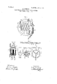
- E represents a leafspring, secured at oneend' to the centrifugally-movable member C, providedwith an adjusting screw e, and carrying at its free end a contact bears against a slide or guide G.
- the spring E forms a connection between the member C and contact F, which is ada ted to permit a centrifugal movement while the centrifu al movement of the mem' ber C will move t e contact F in a substantially circumferential direction along the The slide over which the contact the plate A.
- the switch which is pivoted on the plate A at c, and is prov ded with a restra1rung-spr1ng D opposing-- its cen- F, which,-whenthe motor isat rest v F bridges the contacts H all three simultaneously.
- the contacts H H are two latter forcesF-maylbe adjusted as desired, without in any way altering the effective pressure between electrical contacts.
- the contact F is pivotally mounted on the end of the spring E, as is clearly shown in Figs. 1 and 2, so that this contact is selfalining.
- the two contacts H are alined'in axial direction, as clearly shown in Fig. 2, so that the contact block F necessarily engages both contacts H simultaneously.
- this results in short-circuiting all the phases of the rotor winding provided with leads 7: connecting them to the rotor winding, while the contact F is preferably grounded either through its support or by means of a flexible lead I11 order to obtain a more positive action of the switch I provide in addition to the usual restraining spring D a spring catch I adapted to engage the centrifugally-movable member 0 only at starting.
- This catch serves to restrain the member 0 'against movement until its centrifugal force reaches a predetermined amount. When this amount is reached the member C. slips past the catch I and moves quickly to its extreme odtward position. This snap-action is assisted by the friction of contact-block F on the slide G.
- M represents the primary winding of the motor, which is supplied with threehase current from any suitable source indicated by the line-Wires 1, 2 and 3. on re resents the rotor or secondary winding 0 the motor, which is shortcircuited through the starting resistance R.
- two of the terminals of the windings m are connected by suitable leads directly to the resistance and the third terminal is connected through a ground connection.
- the contact H 'of the centrifugallyactuated switch is connected to the two former terminals, and the contact-block F' is connected through ground to the. third terminal. Consequently, when contact-block hases of the rotor winding are short-circuited, and since the contacts H are arranged to be engaged simultaneously by the block F, as shown in Fig. 2, all three phases are shortcircuited simultaneously.
- my invention comprises a number of.
- a centrifugally-actuated switch carried by the motor arir ature comprising a centrifugally-movable member, a
- a centrifugally-actuated switch carried by prising a centrifugally-movable member, a leaf spring secured at one end to said member and extending in a substantially circumferential direction, a contact carried at the free end of said spring, a slide adapted to be traversed by said contact and to restrain it against centrifugal force, and a contact connected to the motor armature comthe armature winding of the motor and forming a portion of said slide- 3.
- a centrifugally-actuated switch carried bythe motor armature comprising a centrifugally-movable member, a leaf spring secured at one end to said member and extending substantially at right angles to a centrifugal direction, a contact carried at the free end of said spring, a slide adapted to be traversed'by said contact and to restrain it against-centrifugal force, and a contact connected to the armature winding of the motor and forming a portion of said slide.
- a centrifugally-actuated switch carried by the motor armature comprising a centrifugally-movable member, a self-aiming contact carried by said member, a connection between said contact and said member adapted to permit a centrifugal movement of said contact relative to said member and to move said contact substantially at right angles to a centrifu al direction when said member is moved, a slide adapted to be traversed by said contact when moved, and a contact connected to the armature winding of said motor and forming a portion of said slide.
- a centrifugally-actuated switch carried by the motor armature comprising a centrifugally-movable member, a leaf spring secured at one end to said member and extending substantially at right angles to a centrifugal direction, a self-alining contact carried at the free end of said spring, a slide adapted to be traversed by said contact and to restrain it against centrifugal force, and a contact connected to the armature winding of the motor and forming a portion of said slide.
- a centrifugally-actuated switch carried by the motor armature comprising a centrifugally-movable member, a contact block carried by said member and contacts connected to the armature winding of the motor and adapted to be bridged by said contact block;
- centnfugally-actuated switch carried by the motor armature com-- prising a centnfugally-movable member
- self-alining contact block carried by said member, a connection between said contact and said member adapted to permit a centrifugal movement of said contact relative to said member and to move said contact substantially at right angles to a centrifugal direction when said member is moved, a slide adapted to be traversed by said contact when moved, and pair of alined contacts connected to the armature winding of the motor and adapted to be bridged by said contact block.
- a centrifugally-actuated switch carried by the motor armature comprising a c'entrifugally-movable member, a
- a centrifugally-actuated switchc'arried by the motor armature comprising a centrifugally-movable member, a spring secured to said member and opposing its centrifugal movement, a spring catch engaging said member at starting only and adapted .to restrain itfrom movement until the centrifugal force of said member reaches a predetermined amount, a contact carried by said member, and, a second contact connected to the armature winding of the motor and adapted to be engaged by the first contact.
- a resistance connected in series with the motor winding, a centrifugally-movable member carried by the rotor, a contact block'carried by said member, a connection between'said contact block and said member adapted to permit a centrifugal movement of said contact block relative to said member and to move said contact block substantially at right'angles to a centrifugal direction when said member is moved, a slide adapted to be transversed by said contact block when moved, and a pair of short-circuiting contacts connected to said resistance and forming a portion of said slide.
- a resistance connected in series with the rotor winding, a centrifugally-movable member carried by the rotor, a contact block carried by said member and adapted to be moved by said member in a substantially circumferential direction, and a pair of axially-alined short-circuiting contacts connected to said resistance and adapted to be bridged by said contact block:
Description
K. TORNBERG. CENTRIFUGAL SWITCH FOR ELECTRIC MOTORS.
APPLICATION FILED JULY 10 1905.
W/Znesses: //7/ e/7zf0/"; amma/ 2.7 v I final TO/HDe/Z,
PATENTED JUNE 11, 1907.
UNITED srnries KNUT TORNBERG, or LYNN, MASSA PATEN QFF CHUSETTS, ASSIGNQR T GENERAL ELECTRIC ooMriiNY, A'CQBPORATIUN or NEW YORK.
QENTRIFUGAL snares FOR ELEGTREG morons.
Specification of Letters Patent.
Patented am 11, 1907.
Application filed July 10,1905. Serial lilo. 268,951.
To, all whom it may concern:
Be it known that I, KNUT TORNBERG, a
citizen of the United States, residing at Lynn,-
county of Essex, State of- Massachusetts, have invented certain new and useful .Im-
'prove'ments in Centrifugal Switches for Elec- 'tric Motors, of which the following is a specification. Y
My inventionrelates to centrifugally-actuated switches for'electric motors, and is particularly adapted for use in" connection with induction motors of the type designed to start with the resistance in series with the rotor winding and toj run when up to speed with the resistanceshort circuited.
Numerous types of centrifugally-actuated switches have been designed heretofore for the purpose of short-circuiting the rotor resistance automatically when .a predetermined speed is'reache'd.
My invention relates to. this type of iswitcli and its object is to provide a novel arrange ment of the switch, whereby a number of advantageous features are obtained which arenot present-in such switches as heretofore, constructed.
- axOne feature ofiny invention consistsin so in so arranging thecontact carried bythe cuite'd,
mounting the contactcarried by the centrifugally-movable' member of the switch that it is moved by said membersubstantially at right-angles to a centrifugal direction, and is capable of movement in a centrifugal direction relative to said. member, and arranging the contacts to be engaged by the first contact so as to receive the'pressure due to the centrifugal force of thefirst contact. By
means of this arrangement the pressure between the electrical contacts is in no wise dependent upon the centrifugal force of the actuating member, so that the centrifugal force of the actuating member audits restraining spring may be correlated asdesired, without affecting the pressure between the electrical contacts. r
My invention further comprises so arranging' the contacts that the resistances connected to the several phases-of the rotor winding alwaysbe simultaneously short-cir- Another feature ofmy invention consists centrifugally-movable member that it is self-alimng.
Another feature of my invention consists in providing a catch engaging the centrifugal its movement until the centrifugal force reaches a predetermined amount. By this means a more positive action at a more definite speed is obtained than in former structures.
trifugal movement. E represents a leafspring, secured at oneend' to the centrifugally-movable member C, providedwith an adjusting screw e, and carrying at its free end a contact bears against a slide or guide G. It will be seen that the spring Eforms a connection between the member C and contact F, which is ada ted to permit a centrifugal movement while the centrifu al movement of the mem' ber C will move t e contact F in a substantially circumferential direction along the The slide over which the contact the plate A. With this arrangement it will be seen that when the centrifugal member C is thrown outward by centrifugal force, the contact F will be moved along the slide so as to engage the contacts H. The pressure with which contact F will bear upon contacts-H depends only upon the speed of the motor and the weight of contact In other words, it is entirelyindependent of the centrifugal force of the actuating member and the restraining force of the spring Time My inventio'nwill best be understood by of t e contact F relative to the member C,
guide G. 4
7 moves is formed in two portions, one of which comprises the contacts H-su ortedon and insulated from a projection from member at starting and adapted to restrain able actuating member'of. the switch, which is pivoted on the plate A at c, and is prov ded with a restra1rung-spr1ng D opposing-- its cen- F, which,-whenthe motor isat rest v F bridges the contacts H all three simultaneously. The contacts H H are two latter forcesF-maylbe adjusted as desired, without in any way altering the effective pressure between electrical contacts.
The contact F is pivotally mounted on the end of the spring E, as is clearly shown in Figs. 1 and 2, so that this contact is selfalining. The two contacts H are alined'in axial direction, as clearly shown in Fig. 2, so that the contact block F necessarily engages both contacts H simultaneously. As will presently be seen, this results in short-circuiting all the phases of the rotor winding provided with leads 7: connecting them to the rotor winding, while the contact F is preferably grounded either through its support or by means of a flexible lead I11 order to obtain a more positive action of the switch I provide in addition to the usual restraining spring D a spring catch I adapted to engage the centrifugally-movable member 0 only at starting. This catch serves to restrain the member 0 'against movement until its centrifugal force reaches a predetermined amount. When this amount is reached the member C. slips past the catch I and moves quickly to its extreme odtward position. This snap-action is assisted by the friction of contact-block F on the slide G.
Now, referring to Fig. 3, M represents the primary winding of the motor, which is supplied with threehase current from any suitable source indicated by the line-Wires 1, 2 and 3. on re resents the rotor or secondary winding 0 the motor, which is shortcircuited through the starting resistance R. In this figure two of the terminals of the windings m are connected by suitable leads directly to the resistance and the third terminal is connected through a ground connection. The contact H 'of the centrifugallyactuated switch is connected to the two former terminals, and the contact-block F' is connected through ground to the. third terminal. Consequently, when contact-block hases of the rotor winding are short-circuited, and since the contacts H are arranged to be engaged simultaneously by the block F, as shown in Fig. 2, all three phases are shortcircuited simultaneously.
Although I have shown my invention as applied to a three-phase induction motor, it wi be understood that it is not limited to a motor of this particular type. Furthermore, my invention comprises a number of.
features which, while I prefer to use them together, may be used independently, and which I desire to claim whether used together or not.
What I claim as new and desire to secure by Letters Patent of the United States, is:
1. In amotor, a centrifugally-actuated switch carried by the motor arir ature comprising a centrifugally-movable member, a
switch contact operated by said member, a
permit a centrifugal movement of said contact relative to said member, a slide adapted to betraversed by said contactwhen moved eircumferentially and to restrain it against centrifugal force,'and a switch contact connected to the armature windingof the motor and forming a portion of said slide.
2. In a motor, a centrifugally-actuated switch carried by prising a centrifugally-movable member, a leaf spring secured at one end to said member and extending in a substantially circumferential direction, a contact carried at the free end of said spring, a slide adapted to be traversed by said contact and to restrain it against centrifugal force, and a contact connected to the motor armature comthe armature winding of the motor and forming a portion of said slide- 3. In a motor, a centrifugally-actuated switch carried bythe motor armature comprising a centrifugally-movable member, a leaf spring secured at one end to said member and extending substantially at right angles to a centrifugal direction, a contact carried at the free end of said spring, a slide adapted to be traversed'by said contact and to restrain it against-centrifugal force, and a contact connected to the armature winding of the motor and forming a portion of said slide.
4. In a motor, a centrifugally-actuated switch carried by the motor armature comprising a centrifugally-movable member, a self-aiming contact carried by said member, a connection between said contact and said member adapted to permit a centrifugal movement of said contact relative to said member and to move said contact substantially at right angles to a centrifu al direction when said member is moved, a slide adapted to be traversed by said contact when moved, and a contact connected to the armature winding of said motor and forming a portion of said slide.
5. In a motor, a centrifugally-actuated switch carried by the motor armature comprising a centrifugally-movable member, a leaf spring secured at one end to said member and extending substantially at right angles to a centrifugal direction, a self-alining contact carried at the free end of said spring, a slide adapted to be traversed by said contact and to restrain it against centrifugal force, and a contact connected to the armature winding of the motor and forming a portion of said slide.
6. In a motor, a centrifugally-actuated switch carried by the motor armature comprising a centrifugally-movable member, a contact block carried by said member and contacts connected to the armature winding of the motor and adapted to be bridged by said contact block;
8. In a motor, a centnfugally-actuated switch carried by the motor armature com-- prising a centnfugally-movable member, a
self-alining contact block carried by said member, a connection between said contact and said member adapted to permit a centrifugal movement of said contact relative to said member and to move said contact substantially at right angles to a centrifugal direction when said member is moved, a slide adapted to be traversed by said contact when moved, and pair of alined contacts connected to the armature winding of the motor and adapted to be bridged by said contact block.
9. In a motor, a centrifugally-actuated switch carried by the motor armature comprising a c'entrifugally-movable member, a
- catch adapted to engage said member at starting only and to restrain it from movement until the centrifugal force of said member reaches a predetermined amount, a contact carried by said member, and a second contact connected to the armature winding of the motor and adapted to be engaged by the first contact.
10. In a motor, a centrifugally-actuated switchc'arried by the motor armature comprising a centrifugally-movable member, a spring secured to said member and opposing its centrifugal movement, a spring catch engaging said member at starting only and adapted .to restrain itfrom movement until the centrifugal force of said member reaches a predetermined amount, a contact carried by said member, and, a second contact connected to the armature winding of the motor and adapted to be engaged by the first contact.
11. In an induction motor, a resistance connected in series with the motor winding, a centrifugally-movable member carried by the rotor, a contact block'carried by said member, a connection between'said contact block and said member adapted to permit a centrifugal movement of said contact block relative to said member and to move said contact block substantially at right'angles to a centrifugal direction when said member is moved, a slide adapted to be transversed by said contact block when moved, and a pair of short-circuiting contacts connected to said resistance and forming a portion of said slide.
12. In an induction motor, a resistance connected in series with the rotor winding, a centrifugally-movable member carried by the rotor, a contact block carried by said member and adapted to be moved by said member in a substantially circumferential direction, anda pair of axially-alined short-circuiting contacts connected to said resistance and adapted to be bridged by said contact block:
In witnesswhereof, I have hereunto set my'hand this thirtieth day of June 1905.
KNUT TORNBERG.
Witnesses:
JOHN A. MCMANUS,J1., HENRY O. WESTENDARP.
Priority Applications (1)
| Application Number | Priority Date | Filing Date | Title |
|---|---|---|---|
| US26895105A US856433A (en) | 1905-07-10 | 1905-07-10 | Centrifugal switch for electric motors. |
Applications Claiming Priority (1)
| Application Number | Priority Date | Filing Date | Title |
|---|---|---|---|
| US26895105A US856433A (en) | 1905-07-10 | 1905-07-10 | Centrifugal switch for electric motors. |
Publications (1)
| Publication Number | Publication Date |
|---|---|
| US856433A true US856433A (en) | 1907-06-11 |
Family
ID=2924888
Family Applications (1)
| Application Number | Title | Priority Date | Filing Date |
|---|---|---|---|
| US26895105A Expired - Lifetime US856433A (en) | 1905-07-10 | 1905-07-10 | Centrifugal switch for electric motors. |
Country Status (1)
| Country | Link |
|---|---|
| US (1) | US856433A (en) |
Cited By (1)
| Publication number | Priority date | Publication date | Assignee | Title |
|---|---|---|---|---|
| US2748333A (en) * | 1952-04-05 | 1956-05-29 | Lee Royal | Induction motors |
-
1905
- 1905-07-10 US US26895105A patent/US856433A/en not_active Expired - Lifetime
Cited By (1)
| Publication number | Priority date | Publication date | Assignee | Title |
|---|---|---|---|---|
| US2748333A (en) * | 1952-04-05 | 1956-05-29 | Lee Royal | Induction motors |
Similar Documents
| Publication | Publication Date | Title |
|---|---|---|
| US856433A (en) | Centrifugal switch for electric motors. | |
| US2083343A (en) | Cut-out switch for electric motors | |
| US2797080A (en) | Centrifugal mechanism | |
| US1100748A (en) | Speed-regulator. | |
| US735077A (en) | Starting-switch for electric motors. | |
| US771269A (en) | Centrifugal switch. | |
| US780547A (en) | Starting-switch for electric motors. | |
| US2021941A (en) | Generator voltage regulator | |
| US1293532A (en) | Controlling means for electric motors. | |
| US793494A (en) | Controller. | |
| US691188A (en) | Means for regulating electric motors. | |
| US844650A (en) | Alternating-current-retaining device for electric-motor controllers. | |
| US675294A (en) | Electrical controlling apparatus. | |
| US867475A (en) | Motor-starting rheostat. | |
| US910478A (en) | Rheostat. | |
| US1014001A (en) | Alternating-current motor. | |
| US582663A (en) | Electric controller | |
| US1557080A (en) | Short-circuiting device | |
| US894563A (en) | Starting-rheostat. | |
| US1077614A (en) | Controller for electric motors and similar devices. | |
| US452422A (en) | Controlling device for electric motors | |
| US919463A (en) | Electric controlling means. | |
| US322916A (en) | Electric switch | |
| US1019436A (en) | Controlling device for electric motors. | |
| US1487314A (en) | Speed regulator |