US856430A - System of electrical distribution. - Google Patents
System of electrical distribution. Download PDFInfo
- Publication number
- US856430A US856430A US1904234066A US856430A US 856430 A US856430 A US 856430A US 1904234066 A US1904234066 A US 1904234066A US 856430 A US856430 A US 856430A
- Authority
- US
- United States
- Prior art keywords
- points
- conductors
- electrical distribution
- transformers
- auto
- Prior art date
- Legal status (The legal status is an assumption and is not a legal conclusion. Google has not performed a legal analysis and makes no representation as to the accuracy of the status listed.)
- Expired - Lifetime
Links
Images
Classifications
-
- H—ELECTRICITY
- H01—ELECTRIC ELEMENTS
- H01R—ELECTRICALLY-CONDUCTIVE CONNECTIONS; STRUCTURAL ASSOCIATIONS OF A PLURALITY OF MUTUALLY-INSULATED ELECTRICAL CONNECTING ELEMENTS; COUPLING DEVICES; CURRENT COLLECTORS
- H01R25/00—Coupling parts adapted for simultaneous co-operation with two or more identical counterparts, e.g. for distributing energy to two or more circuits
- H01R25/006—Coupling parts adapted for simultaneous co-operation with two or more identical counterparts, e.g. for distributing energy to two or more circuits the coupling part being secured to apparatus or structure, e.g. duplex wall receptacle
Definitions
- My invention relates to systems of electrical distribution, and it has for its object to provide a system of distribution for alternating currents such that a multiplicity of voltages may be conveniently and economically derived from a single source of energy.
- induction motors may be operated most efficiently by means of higher voltages than those which are desirable for Nernst lamps and carbon filament lamps are generally operated at lower voltages than either motors or Nernst lamps. It follows that these different varieties of translating devices are rarely operated from the same generator, except in cases where step-down transformers are used.
- My invention provides means for avoiding the use of two-winding transformers and for obtaining, at the same time, a low voltage for lighting purposes and a comparatively high voltage for general distribution or motor service from a single source of energy.
- Figure 1 is a diagram of a system of distribution which embodies my invention
- Fig. 2 is a similar view of a modification.
- auto-transformers 1 and 2 are connected to diametrically oppo site points of the armature winding 3 of a two-phase generator 4, and to the middle points 5 of these transformers are connected balancing or neutral conductors 7.
- the conductors 7 may be connected together by means of a conductor 7 and may also be grounded, as indicated at G, in order to insure a definite, limited difference of potential between each of the other conductors and the ground.
- These transformers 1 and 2 may be so placed upon the spider of the armature as to revolve therewith, or the armature winding may be connected, by means of collector rings and brushes, to stationary auto-transformers.
- the volt-age between the conductors 8 and 9 and between the conductors 10 and 11 will be that of the generator, while the voltage between any one of the conductors 8, Q, 10 and 11 and the neutral conductors 7 will be 220 volts. If taps 12, 13, 1.4 and 15 are taken from the middle points of the halves of the auto-transformers, the difference in potential between conductors 12 and 13 and between conductors 1 1 and 15 will be 220 volts, while that between each of said conductors and the grounded neutral conductor 7 will be 110 volts.
- induction motors 16 may be operated economically from the 140 volt conductors, Nernst lamps 17 from the 220 volt conductors and carbon lilament lamps 18 from the 110 volt conductors, or any other suitable arrangement of translating devices may be made.
- Intermediate taps or leads other than those from the middle or neutral points of the auto-transformers may be made from any desired number of points either in lieu of or 111 addition to those from the points 6, as specifically indicated in the drawing. It will be readily seen that the number of such intermediate taps or leads may be varied indefinitely in order to obtain any (l6Sl1 ed range of voltages for the operation of incandescent lamps or other translating devices.
- the conductors 8, 9, 10, 11, 12, 13, 14 and 15 and the translating devices 16, 17 and 18 may have the same arrangement and may be adapted to the same voltages and other con ditions as the corresponding elements of the system illustrated in Fig. 1.
- I omit the transformers and employ a generator 19 having Stan-connected, station ary armature windings 20 to which the distributing conductors are connected, the points 5", 6, 8 9, 10 and 11 of such connection corresponding to the points in the transformer windings to which the conductors are connected in the system shown in Fig. 1.
- a system of electrical distribution comprising a two-phase generator, autotrans formers having their terminals connected to the maximum potential armature points cor responding to the respective phases and having their middle points connected together and grounded, and distributing conductors connected to the middle points, to the extremities and to points intermediate the mi ddle points and the extremities of the autotransformer windings.
- a system of electrical distribution comprising a polyphase generator, auto-transformers connected to maximum potential armature points corresponding to the respective phases and having their middle points connected together and. grounded, and. distributing conductors respectively connected to the extremities and to a plurality of intermediate points in said auto-transformer windings.
- a system of electrical distribution comprising a source of two-phase electrical energy, sets of translating devices adapted. for diiierent voltages, and two sets of supply conductors that are respectively connected. to the middle points, the extremities and intermediate points of two-phase windin with which the said. source of energ is provided, the middle points of the windings being connected together and grounded.
- a system of electrical distribution comprising a source oi polyphase electrical energy and distributing conductors that are respectively connected to the middle points, to the extremities and to intermediate points in windings with which the said source of energy is provided, the middle points of the generator windings being connected together and grounded.
Description
No. 856,430. PATENTED JUNE 11, 1907 S. B. STORER.
SYSTEM OF ELECTRICAL DISTRIBUTION. APPLICATION FILED NOV. 23, 1904.
I mvemon ATTORNEY unirnn srArns PATENT orrion.
SIMON B. STORER, OF SYRACUSE, NEIV YORK, ASSIGNOR TO WESTINGHOUSE ELECTRIC & MANUFACTURING COMPANY, A CORPORATION OF PEN N- SYLVANIA.
SYSTEM OF ELECTRICAL DISTRIBUTION.
Specification of Letters Patent.
Patented June 11, 1907.
To a whom, it may concern:
Be it known that I, SIMON B. S'ronnn, a citizen of the United States, and a resident of Syracuse, in the county of Onondaga and State of New York, have invented a new and useful Improvement in,Systems of Electrical Distribution, of which the following is a specification.
My invention relates to systems of electrical distribution, and it has for its object to provide a system of distribution for alternating currents such that a multiplicity of voltages may be conveniently and economically derived from a single source of energy.
As is well known, induction motors may be operated most efficiently by means of higher voltages than those which are desirable for Nernst lamps and carbon filament lamps are generally operated at lower voltages than either motors or Nernst lamps. It follows that these different varieties of translating devices are rarely operated from the same generator, except in cases where step-down transformers are used.
My invention provides means for avoiding the use of two-winding transformers and for obtaining, at the same time, a low voltage for lighting purposes and a comparatively high voltage for general distribution or motor service from a single source of energy.
Such a system finds practical application in towns or villages and in factories where mixed lighting and power service is desired.
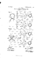
In the accompanying drawing, Figure 1 is a diagram of a system of distribution which embodies my invention, and Fig. 2 is a similar view of a modification.
Referring first to Fig. l, auto-transformers 1 and 2 are connected to diametrically oppo site points of the armature winding 3 of a two-phase generator 4, and to the middle points 5 of these transformers are connected balancing or neutral conductors 7. The conductors 7 may be connected together by means of a conductor 7 and may also be grounded, as indicated at G, in order to insure a definite, limited difference of potential between each of the other conductors and the ground. These transformers 1 and 2 may be so placed upon the spider of the armature as to revolve therewith, or the armature winding may be connected, by means of collector rings and brushes, to stationary auto-transformers.
Assuming that the generator 4 is wound to deliver 440 volts to each of the two-phase circuits, the volt-age between the conductors 8 and 9 and between the conductors 10 and 11 will be that of the generator, while the voltage between any one of the conductors 8, Q, 10 and 11 and the neutral conductors 7 will be 220 volts. If taps 12, 13, 1.4 and 15 are taken from the middle points of the halves of the auto-transformers, the difference in potential between conductors 12 and 13 and between conductors 1 1 and 15 will be 220 volts, while that between each of said conductors and the grounded neutral conductor 7 will be 110 volts. Evidently, then, induction motors 16 may be operated economically from the 140 volt conductors, Nernst lamps 17 from the 220 volt conductors and carbon lilament lamps 18 from the 110 volt conductors, or any other suitable arrangement of translating devices may be made.
Intermediate taps or leads other than those from the middle or neutral points of the auto-transformers may be made from any desired number of points either in lieu of or 111 addition to those from the points 6, as specifically indicated in the drawing. It will be readily seen that the number of such intermediate taps or leads may be varied indefinitely in order to obtain any (l6Sl1 ed range of voltages for the operation of incandescent lamps or other translating devices.
Referring now to Fig. 2 of the drawing, the conductors 8, 9, 10, 11, 12, 13, 14 and 15 and the translating devices 16, 17 and 18 may have the same arrangement and may be adapted to the same voltages and other con ditions as the corresponding elements of the system illustrated in Fig. 1. In this modifi cation, I omit the transformers and employ a generator 19 having Stan-connected, station ary armature windings 20 to which the distributing conductors are connected, the points 5", 6, 8 9, 10 and 11 of such connection corresponding to the points in the transformer windings to which the conductors are connected in the system shown in Fig. 1. I
It is therefore to be understood that my invention is not to be limited to any specific number of taps or leads or to the character of the translating devices employed, the vol tages and translating devices which have been illustrated and described. being in no sense restrictive.
I claim as my invention:
1. A system of electrical distribution comprising a two-phase generator, autotrans formers having their terminals connected to the maximum potential armature points cor responding to the respective phases and having their middle points connected together and grounded, and distributing conductors connected to the middle points, to the extremities and to points intermediate the mi ddle points and the extremities of the autotransformer windings.
2. A system of electrical distribution com prising a two-phase generator, auto-transformers connected to maximum potential armature points corresponding to the respective phases and having their middle points connected together and grounded, and distributing conductors respectively connected to the extremities, to the middle points and to intermediate points of the halves of said. autotransformer windings.
3. The combination with a twophase gen erator and distributing conductors leading therefrom, of auto-transformers having their middle points connected together and grounded and having their extremities connected to the maximum potential armature points cor responding to the respective phases, and additional distributing conductors which are connected to the middle points and to the middle points of the halves of the auto-transformer windings.
4. A system of electrical distribution comprising a polyphase generator, auto-transformers connected to maximum potential armature points corresponding to the respective phases and having their middle points connected together and. grounded, and. distributing conductors respectively connected to the extremities and to a plurality of intermediate points in said auto-transformer windings.
5. A system of electrical distribution comprising a source of two-phase electrical energy, sets of translating devices adapted. for diiierent voltages, and two sets of supply conductors that are respectively connected. to the middle points, the extremities and intermediate points of two-phase windin with which the said. source of energ is provided, the middle points of the windings being connected together and grounded.
6. A system of electrical distribution comprising a source oi polyphase electrical energy and distributing conductors that are respectively connected to the middle points, to the extremities and to intermediate points in windings with which the said source of energy is provided, the middle points of the generator windings being connected together and grounded.
In testimony whereof, I have hereunto subscribed my name this 17th day ol November 1904.
SIMON B. SIOR'ER.
Witnesses:
J. C. MoRsE, BIRNEY ITIINES.
Priority Applications (1)
| Application Number | Priority Date | Filing Date | Title |
|---|---|---|---|
| US1904234066 US856430A (en) | 1904-11-23 | 1904-11-23 | System of electrical distribution. |
Applications Claiming Priority (1)
| Application Number | Priority Date | Filing Date | Title |
|---|---|---|---|
| US1904234066 US856430A (en) | 1904-11-23 | 1904-11-23 | System of electrical distribution. |
Publications (1)
| Publication Number | Publication Date |
|---|---|
| US856430A true US856430A (en) | 1907-06-11 |
Family
ID=2924885
Family Applications (1)
| Application Number | Title | Priority Date | Filing Date |
|---|---|---|---|
| US1904234066 Expired - Lifetime US856430A (en) | 1904-11-23 | 1904-11-23 | System of electrical distribution. |
Country Status (1)
| Country | Link |
|---|---|
| US (1) | US856430A (en) |
-
1904
- 1904-11-23 US US1904234066 patent/US856430A/en not_active Expired - Lifetime
Similar Documents
| Publication | Publication Date | Title |
|---|---|---|
| US2307527A (en) | Electrical induction apparatus | |
| US856430A (en) | System of electrical distribution. | |
| US2205476A (en) | Transforming apparatus | |
| US607621A (en) | System of electrical distribution | |
| US1738726A (en) | Regulating device for electrical systems | |
| US412932A (en) | System of distribution by alternating electric currents | |
| US729748A (en) | Alternating-current transformer. | |
| US571270A (en) | Setts | |
| US2059024A (en) | Rotary transformer | |
| US2546011A (en) | Three-phase autotransformer | |
| US740189A (en) | System of electrical distribution. | |
| US1082561A (en) | System of distribution. | |
| US382282A (en) | Method Of Converting And Distributing Electric Current | |
| US745594A (en) | Multivoltage electric generator. | |
| US390413A (en) | Nikola | |
| US760480A (en) | System of electrical distribution. | |
| US440224A (en) | Sebastian ziani de ferranti | |
| US550355A (en) | System of electrical distribution | |
| US381970A (en) | System Of Electrical Distribution | |
| US730828A (en) | System of phase transformation. | |
| US373037A (en) | System of electrical distribution | |
| US487543A (en) | System of electrical distribution | |
| US695944A (en) | System of electrical distribution. | |
| US1084469A (en) | Voltage-regulating means. | |
| US726445A (en) | Means for connecting multiphase windings. |