US856423A - Ventilating dynamo-electric machines. - Google Patents
Ventilating dynamo-electric machines. Download PDFInfo
- Publication number
- US856423A US856423A US24785105A US1905247851A US856423A US 856423 A US856423 A US 856423A US 24785105 A US24785105 A US 24785105A US 1905247851 A US1905247851 A US 1905247851A US 856423 A US856423 A US 856423A
- Authority
- US
- United States
- Prior art keywords
- core
- members
- shaft
- dynamo
- ventilating
- Prior art date
- Legal status (The legal status is an assumption and is not a legal conclusion. Google has not performed a legal analysis and makes no representation as to the accuracy of the status listed.)
- Expired - Lifetime
Links
Images
Classifications
-
- H—ELECTRICITY
- H02—GENERATION; CONVERSION OR DISTRIBUTION OF ELECTRIC POWER
- H02K—DYNAMO-ELECTRIC MACHINES
- H02K9/00—Arrangements for cooling or ventilating
- H02K9/02—Arrangements for cooling or ventilating by ambient air flowing through the machine
- H02K9/04—Arrangements for cooling or ventilating by ambient air flowing through the machine having means for generating a flow of cooling medium
- H02K9/06—Arrangements for cooling or ventilating by ambient air flowing through the machine having means for generating a flow of cooling medium with fans or impellers driven by the machine shaft
Definitions
- Fig. 2 is an end ele- I UNITED STATES PATENT oEEIoE.
- My present invention has for its object improvements in means for ventilating dynamo electric machines, through air currents generated by the revolution of the rotating member of the machine.
- Figure 1 is an elevation with the parts broken away and in section of a dynamo electric machine enivation of the body of the rotating member of the machine shown in Fig. 1; and Fig. 3 is anend elevation and Fig. 4 a view at right construe angles thereto showing a modified detail of Referring to the drawin' s,.1 represents the frame or casing of an int uction motor embodying my invention.
- the inner periphery of the frame is provided with a nu her of parallel projections or ribs against th inner face of which the annular stator core '3 is secured by means of dovetail connections or otherwise.
- the ar rangement is such that arc-shaped spaces are formed between the outerperiphery of the core 3', the inner'periphery of the frame 1, and the projections or ribs 2.
- the bonnets 5 are 'each' provided with a bearing box 6 in which suitable bearings are supported for theshaft 70f the rotor.
- the shaft 7 has tapered portions terminating in oil-throwing ridges 7 located one*in each box. 7 These tapered portions and ridges are intended to operate to prevent the flow of oil along the shaft out of the bearing boxes in the usual manner.- Between the inner ends of the bearings is located the rotor core 8 which is keyed to the shaft 7. One extended end of the shaft 7 carries a power transmitting pullev 9.
- the rotor core proper is made up of laminae of magnetic material which are keyed to the shaft. At the ends of the core proper are sheet copper disks 9 which serve as the end connections for the heavy bar conductors 10, the ends of which may be upset as shown to hold them in place.
- a member 11 which may be formed of cast metal.
- the member 11 is formed with a portion, part or member 12 in the shape of a truncated cone, the base of which bears against the corresponding endof the core 8. The smaller and outer end of each portion 12 terminates in or near the radial plane touched by the inner end of the corresponding bearing box 6.
- each portion 12 projects outward slightly beyond the inner end of the corresponding bearing box 6, the outer diameter of which at that point is sli htly less than the inner diameter of the smaIl 'end of the portion 12.
- the member 11 is also provided vanes or wings 13 which may be located in radial lanes as shown," or may be inclined to such p anes if desirable.
- Ears 14 projectlng at right angles to the bodies of some of'the blades 13 are provided 1 with perforations through which pass the boltsemployed to securethe members 11 to the core. It will be observed that the members 11 are placed so that when suitably proportioned they may serve as the end members of the rotor core proper between which the laminae of the core may be clam ed.
- the rotation '0 the shaft 7 and core 8 causes air currents to be generated by the fan blades 13, which flow outward through the end connections of the windings 3 of the stator..
- the air thus moved may enter the motor'casing througlLopenings 5 in the bonnets 5, and may flow outward through openings 15 in the motor frame proper.
- the openings 15 it will, of course, be understood communicate with the spaces between the core 3. and the peri hery of the motor frame.
- the air thus move not only cools the stator core and windings, but also cools the rotor members 11 serve as shields, barriers or with the exception that the member 11 cor shields extending from the body to the beardisks 9 and the ends of the conductor bars 10.
- the rotor is also cooled by reason of the fact that the members 1 1 are in direct en- 'agement with the outer disks 9,which being formed of copper conduct heat rapidly from the core and its conductors to the members 11, thus materially increasing the heat radiating surface of the rotor.
- the construction shown in Figs. 3 and d is substantially like that shown in Figs. 1 and 2 responding to the member 11 of the first described construction is formed out of sheet metal, the conical portion 12 being s un up and the fan blades 13 being in the orm of projections turned at right angles from an outward radial extension from the large end of theconical portion 12.
- a rotating body In a dynamo electric machine, a rotating body, fan. blades carried by the ends thereof, bearings for the body, and guards or 2.
- a rotating shaft In a dynamo electric machine, a rotating shaft, a bearing therefor, a core or body carried by the shaft, fan blades secured to the end. of the core or body adjacent the bearing, and a shield carried by the core and extending to the hearing.
- a rotating shaft In a dynamo electric machine, a rotating shaft, a core or body carried thereby, a member secured thereto provided with fan blades or vanes, and a barrier integrally connected thereto and extending from the core to the bearing.
- an external stationary core an internal rotating core or body, a shaft carrying said rotating core or body, bearings for the shaft and members secured to each end of the core body, each ofsaid members comprising fan blades or vanes, and a guard or barrier portion which extends to the bearing to prevent the air currents produced by the fan blades from drawing oil out of the bearings.
- a rotating shaft a bearing therefor, a core or body carried bythe shaft, fan blades secured to said body adjacent the bearing, and a shield ,carried by the core and overhanging the bearing;
- a casing In a dynamo electric machine, a casing, bearing boxes projecting therein and carried bythe ends of said casing, a shaft journaled in said bearing boxes, a core body carried by the shaft, shells in the form of truncated cones secured one to each end of the core body, the base end of each cone being adjacent the core and the smaller end of each shell surrounding the inner end of the corresponding bearing box, and fan blades secured to each end of the core body externally of the shell members.
- a frame member a stationary core supported thereby, end members secured to opposite ends of said frame member, each of said end members being provided with an inwardly projecting bearing box, a rotating shaft journaled in said bearing boxes, a rotor core carried by the shaft in co-operative relation with the stationary core, shell-like projections or momhers from each end of the core, which project over the ends of the corresponding bearing boxes, conductorscarried by the rotor core and end connections therefor engaging said shell members, and fan blades carried by the rotor core externally of the shell members.
Description
PATENTED JUNE 11, 1907.
v H. G. REIST.
VENTILATING DYNAMO ELEGTRIO MACHINES.
APPLICATION FILED MARJ. 1905.
INVENTOR Henry G. P163 i at f I I f a bodying my invention; Fig. 2 is an end ele- I UNITED STATES PATENT oEEIoE.
ELECTRIC COMPANY, A CORPORATION OF NEW YORK.
VENTILATING DYNAMd-ELECTRIC MACHINES.
Specification of Letters Patent.
I Patented June 11, 1907. I
Application filed March-1, 1905. Serial No. 247,851.
To all whom it may concern.-
Be it known that I, HENRY G. REIsT, a citizen of the United States, residing at Schenectad county of Schenectady, State of New Yor r, have invented certain new and useful Improvements in Ventilating Dynamo- Elect-ric Machines, of which the following is a specification.
My present invention has for its object improvements in means for ventilating dynamo electric machines, through air currents generated by the revolution of the rotating member of the machine.
The various features of novelty which characterize my invention are pointed out with particularity in the claims annexed to and forming a part of this specification. For a better understanding of my invention, however, reference may be had to the accompanying drawings and description in which I have illustratei and described forms in which myinvention may be embodied.
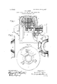
Referring to the drawings, Figure 1 is an elevation with the parts broken away and in section of a dynamo electric machine enivation of the body of the rotating member of the machine shown in Fig. 1; and Fig. 3 is anend elevation and Fig. 4 a view at right construe angles thereto showing a modified detail of Referring to the drawin' s,.1 represents the frame or casing of an int uction motor embodying my invention. The inner periphery of the frame is provided with a nu her of parallel projections or ribs against th inner face of which the annular stator core '3 is secured by means of dovetail connections or otherwise. I It will be observed that the ar rangement is such that arc-shaped spaces are formed between the outerperiphery of the core 3', the inner'periphery of the frame 1, and the projections or ribs 2.
To the ends of the frame 1 are'secured the usual end members or bonnets 5. The bonnets 5 are 'each' provided with a bearing box 6 in which suitable bearings are supported for theshaft 70f the rotor. The shaft 7 has tapered portions terminating in oil-throwing ridges 7 located one*in each box. 7 These tapered portions and ridges are intended to operate to prevent the flow of oil along the shaft out of the bearing boxes in the usual manner.- Between the inner ends of the bearings is located the rotor core 8 which is keyed to the shaft 7. One extended end of the shaft 7 carries a power transmitting pullev 9.
The rotor core proper is made up of laminae of magnetic material which are keyed to the shaft. At the ends of the core proper are sheet copper disks 9 which serve as the end connections for the heavy bar conductors 10, the ends of which may be upset as shown to hold them in place. Against each end of the rotor core 8 in the construction shown in Figs. 1 and 2 is secured a member 11 which may be formed of cast metal. The member 11 is formed with a portion, part or member 12 in the shape of a truncated cone, the base of which bears against the corresponding endof the core 8. The smaller and outer end of each portion 12 terminates in or near the radial plane touched by the inner end of the corresponding bearing box 6. In the constructlon shown in thedrawings 'the outer end of each portion 12 projects outward slightly beyond the inner end of the corresponding bearing box 6, the outer diameter of which at that point is sli htly less than the inner diameter of the smaIl 'end of the portion 12. with integral outwardly-extending fan blades,
The member 11 is also provided vanes or wings 13 which may be located in radial lanes as shown," or may be inclined to such p anes if desirable. Ears 14 projectlng at right angles to the bodies of some of'the blades 13 are provided 1 with perforations through which pass the boltsemployed to securethe members 11 to the core. It will be observed that the members 11 are placed so that when suitably proportioned they may serve as the end members of the rotor core proper between which the laminae of the core may be clam ed.
The rotation '0 the shaft 7 and core 8 causes air currents to be generated by the fan blades 13, which flow outward through the end connections of the windings 3 of the stator.. The air thus moved may enter the motor'casing througlLopenings 5 in the bonnets 5, and may flow outward through openings 15 in the motor frame proper. The openings 15 it will, of course, be understood communicate with the spaces between the core 3. and the peri hery of the motor frame. The air thus move not only cools the stator core and windings, but also cools the rotor members 11 serve as shields, barriers or with the exception that the member 11 cor shields extending from the body to the beardisks 9 and the ends of the conductor bars 10. The rotor is also cooled by reason of the fact that the members 1 1 are in direct en- 'agement with the outer disks 9,which being formed of copper conduct heat rapidly from the core and its conductors to the members 11, thus materially increasing the heat radiating surface of the rotor. The portions 12 of vthe guards to prevent oils being sucked out of the bearing boxes by the fan blades. It is not essential in all cases that the portions 12 be conical as shown, though with the construction illustrated in the drawing it is desirable that they should be so shaped, as they then guide the air currents generated by the fan blades into the proper outward paths.
. The construction shown in Figs. 3 and d is substantially like that shown in Figs. 1 and 2 responding to the member 11 of the first described construction is formed out of sheet metal, the conical portion 12 being s un up and the fan blades 13 being in the orm of projections turned at right angles from an outward radial extension from the large end of theconical portion 12.
It will be obvious to all those skilled in the art that the construction which I have de-, scribed is simple and efficient and that many changes may be made in the form in which my invention is employed without departing from its spirit. In particular it is obvious that the invention may be advantageously employed with other machines than induction motors.
What I claim as new and desire to secure by Letters Patent of the United States, is:
1. In a dynamo electric machine, a rotating body, fan. blades carried by the ends thereof, bearings for the body, and guards or 2. In a dynamo electric machine, a rotating shaft, a bearing therefor, a core or body carried by the shaft, fan blades secured to the end. of the core or body adjacent the bearing, and a shield carried by the core and extending to the hearing. I
3. In a dynamo electric machine, a rotating shaft, a core or body carried thereby, a member secured thereto provided with fan blades or vanes, and a barrier integrally connected thereto and extending from the core to the bearing.
4. In a dynamo electric machine, an external stationary core, an internal rotating core or body, a shaft carrying said rotating core or body, bearings for the shaft and members secured to each end of the core body, each ofsaid members comprising fan blades or vanes, and a guard or barrier portion which extends to the bearing to prevent the air currents produced by the fan blades from drawing oil out of the bearings.
5. In an induction motor, a stationaryv core, end members in fixed relation thereto, each of said end members being provided with an inwardly projecting'bearing box, a
rotating shaft and bearings therefor in said bearing boxes, a rotating core carried by the shaft in co-operative relation with the stationary core, shell-like members projecting from each end of the core which extend over the ends of the corresponding bearing boxes, and fan blades carried by the rotating core without the shell members. I
6. In a dynamo electric machine, a rotating shaft, a bearing therefor, a core or body carried bythe shaft, fan blades secured to said body adjacent the bearing, and a shield ,carried by the core and overhanging the bearing;
8. In an induction motor, a frame member, a stationary core supported thereby, end members secured to opposite ends of said frame member, each of said end members being provided with an inwardly projecting bearing box, a rotating shaft journaled in said bearing boxes, a rotor core carried by the shaft in co-operative relation with the stationary core, shell-like projections or momhers from each end of the core, which project over the ends of the corresponding bearing boxes, conductorscarried by the rotor core and end connections therefor engaging said shell members, and fan blades carried by the rotor core externally of the shell members.
In witness whereof I have hereunto set my hand this 16th day of February, 1905.
HENRY REIST. Witnesses:
BENJAMIN B. HULL,
HELEN 'ORFORD.
IIO
Priority Applications (1)
| Application Number | Priority Date | Filing Date | Title |
|---|---|---|---|
| US24785105A US856423A (en) | 1905-03-01 | 1905-03-01 | Ventilating dynamo-electric machines. |
Applications Claiming Priority (1)
| Application Number | Priority Date | Filing Date | Title |
|---|---|---|---|
| US24785105A US856423A (en) | 1905-03-01 | 1905-03-01 | Ventilating dynamo-electric machines. |
Publications (1)
| Publication Number | Publication Date |
|---|---|
| US856423A true US856423A (en) | 1907-06-11 |
Family
ID=2924878
Family Applications (1)
| Application Number | Title | Priority Date | Filing Date |
|---|---|---|---|
| US24785105A Expired - Lifetime US856423A (en) | 1905-03-01 | 1905-03-01 | Ventilating dynamo-electric machines. |
Country Status (1)
| Country | Link |
|---|---|
| US (1) | US856423A (en) |
Cited By (2)
| Publication number | Priority date | Publication date | Assignee | Title |
|---|---|---|---|---|
| US2499390A (en) * | 1944-07-10 | 1950-03-07 | Master Electric Co | Rotor for alternating current machines |
| US5144175A (en) * | 1991-05-15 | 1992-09-01 | Siemens Energy & Automation, Inc. | Cooling fan for electric motors |
-
1905
- 1905-03-01 US US24785105A patent/US856423A/en not_active Expired - Lifetime
Cited By (2)
| Publication number | Priority date | Publication date | Assignee | Title |
|---|---|---|---|---|
| US2499390A (en) * | 1944-07-10 | 1950-03-07 | Master Electric Co | Rotor for alternating current machines |
| US5144175A (en) * | 1991-05-15 | 1992-09-01 | Siemens Energy & Automation, Inc. | Cooling fan for electric motors |
Similar Documents
| Publication | Publication Date | Title |
|---|---|---|
| US3383529A (en) | Dynamoelectric machine cooling | |
| US2735950A (en) | brown | |
| US2293508A (en) | Dynamoelectric machine | |
| US11349370B2 (en) | Rotary electric machine with shrink-fitted bearing | |
| US856423A (en) | Ventilating dynamo-electric machines. | |
| US3383530A (en) | Dynamoelectric machine | |
| GB293590A (en) | Improvements in or relating to cooling arrangements for dynamo electrical machines | |
| US2185728A (en) | Dynamo-electric machine | |
| WO2019234967A1 (en) | Dynamo-electric machine | |
| US973565A (en) | Means for ventilating dynamo-electric machines. | |
| US1043887A (en) | Dynamo-electric machine. | |
| US2159695A (en) | Induction motor rotor | |
| US1196345A (en) | Ventilating means for dynamo-electric machines. | |
| US1908158A (en) | Alternating current dynamo-electric machine | |
| US872708A (en) | Induction-motor. | |
| US1300373A (en) | Dynamo-electric machine. | |
| US849706A (en) | Cooling dynamo-electric machines. | |
| US1141860A (en) | Electric motor or generator. | |
| US1677433A (en) | Electric motor and dynamo machine | |
| US1137510A (en) | Dynamo-electric machine. | |
| US972850A (en) | Rotary field member of dynamo-electric machines. | |
| US894533A (en) | Dynamo-electric machine. | |
| JP6147428B2 (en) | Rotating electrical machine rotor | |
| GB333616A (en) | Improvements in dynamo electric machinery | |
| US927318A (en) | Dynamo-electric machine. |