US856414A - Dynamo-electric machine. - Google Patents
Dynamo-electric machine. Download PDFInfo
- Publication number
- US856414A US856414A US33182206A US1906331822A US856414A US 856414 A US856414 A US 856414A US 33182206 A US33182206 A US 33182206A US 1906331822 A US1906331822 A US 1906331822A US 856414 A US856414 A US 856414A
- Authority
- US
- United States
- Prior art keywords
- interpoles
- dynamo
- poles
- electric machine
- spaces
- Prior art date
- Legal status (The legal status is an assumption and is not a legal conclusion. Google has not performed a legal analysis and makes no representation as to the accuracy of the status listed.)
- Expired - Lifetime
Links
Images
Classifications
-
- H—ELECTRICITY
- H02—GENERATION; CONVERSION OR DISTRIBUTION OF ELECTRIC POWER
- H02K—DYNAMO-ELECTRIC MACHINES
- H02K23/00—DC commutator motors or generators having mechanical commutator; Universal AC/DC commutator motors
- H02K23/02—DC commutator motors or generators having mechanical commutator; Universal AC/DC commutator motors characterised by arrangement for exciting
- H02K23/22—DC commutator motors or generators having mechanical commutator; Universal AC/DC commutator motors characterised by arrangement for exciting having compensating or damping windings
Definitions
- Y My invention relates to im' rovements in dynamo electric-machines o the type in which auxiliary interpoles are located in the 1' 5' spaces between the main poles of the machine for the purpose'of securing a more perw fect commutation.
- the interpoles act to correct, to some extent, the distortion of the field due to the armature reaction, and to enerate in the short circuited coil which is eing c0m-' mutated a current corresponding in direc' tion to the current which is flowing in the .circuitwith which the short circuited coil is z 5 about to be connected by the rotation of the I. armature, Ithas been customary to locate.
- the object of my invention is to take advantage of this reduction in the number of interpoles for the purpose of reducing the cost and dimensions of the dynamo electric machine and to so proportion the magnetic circuit as to be able to utilize all or a reater part of the space between the main and interpoles for the coils used to magnetize these poles.
- M M M M and M represent the main poles of the machine which are energized by the current passing through the coils C C C and C;
- v I and I are the interpoles, provided with the coils C and C. It will be seen that there are only two interpoles and that the location of the armature coils is such that the coils of which one portion isbeneath the inter pole I have their other portions in the inter-' polar space between the poles M and M", and the coils which are acted upon by the interpole I have their other portions in the space etween the main poles M and M and it is thus possibleto dispense with interpoles between the main poles M and lVI,and-M and mainpoles, I am able to spacetheir pol'e 'I'a'ces symmetrically around theperiphery of the armature, while their energizing coils and cores are unsymmetrically spaced, thus allowing the coils of the interpoles to be so placed that they do not interfere with the main pole coils, and all the'space between the pole cores may be utilized forwindings if desired.
- a dynamo electric machine havingmain f in presence of two w tnesses.
- the main polefaces being'sy n1- metrically spaced about the periphery of the armature while their cores are unsymmetrically spaced, thereby allowing space-.for the coils of'theinterpoles.
- A- dynamo electric machine having spaces of different extent between the cores of the mam field poles, and-an interpole located in the larger inter-core s ace.
- a dynamo electric m'ac line having a plurahty of mam poles with unsymmetrically spaced cores, half as many interpoles'located in alternate intercore spaces-the intercore spaces containing interpoles beinglarger than e spaces which-do not contain interpoles, and t 1e polar tips ofthe main poles belng extended in the tllIGC'tlOIl of the adjacent interpole'tosecure a symmetrical arrangement of the. polar faces, subs t antially as described. 1 A.
- a dynamo electric machine having a plurality of 'mai-n poles and half asmany i11- terpoles, the main pole faces being symmetrically spaced about the armature, and the 1nter-core'spacos containing interpoles being larger than theinter-corc spaces which do not contain interpoles 5.
- a dynamo electric machine havinga plurality ofimain poles and half as many interpoles located in alternate spaces between the maiirpoles, theffield frame being split through the interpolar spaces which (lo-not contain lnterpoles, the windings of the main poles being unsymmetrically.Larranged so that these windings and" thewindings 01 the inter-poles substantially fill the frame, sub- 6';
- a dynamo-electric,machine havinga plurality of main poles with unsymmetri-cally spaced cores, half asimany'mt'erpoles located in alternate lntercoreispace's, and the vfield frame being. split through the interpolar.
- a dynamo electric machine having spaces of different extent between the cores of the main field poles, and an interpole located in the larger intercom-space.
Description
N0. 856,414. PATENTED JUNE 11, 1907. G. A. MUDGE.
DYNAMO ELECTRIC MACHINE. APPLICATION FILED we. 24. 1906.
Suwenkoz fl a z i ji 38g 74 "CHARLES A. MUDGE, OF NEW YORK,
N. Y., ASSIGNOR TO ELEOTRO DY- NAMIO COMPANY, OF BAYONNE, NEW JERSEY, A CORPORATION OF NEW JERSEY.
DYNAMO-ELECTRIC MACHINE.
Specification of Letters Patent.
Patented June- 11, 1907.
Application filed August 24,1906- Serial No. 331,822.
I Tea/ll whom it may concern:
Be it known that I, CHARLES A. MUDGE, a citizen of the United States, residing at New York, in the county of New York and State v I '5' of New York, have invented certain new and useful Improvements in Dynamo-Electric =1 Machines; and I do hereby declare the foll lowing to be a full, clear, and eXact-descrip I ',tlOIl of the invention, such as will enable others skilled in the art to which it appertams to make and use the same."
" Y My invention relates to im' rovements in dynamo electric-machines o the type in which auxiliary interpoles are located in the 1' 5' spaces between the main poles of the machine for the purpose'of securing a more perw fect commutation. In machines of this 1 character, the interpoles act to correct, to some extent, the distortion of the field due to the armature reaction, and to enerate in the short circuited coil which is eing c0m-' mutated a current corresponding in direc' tion to the current which is flowing in the .circuitwith which the short circuited coil is z 5 about to be connected by the rotation of the I. armature, Ithas been customary to locate.
an'inter, ole in every space between the main poles o the machine, the interpole corresponding in polarity with the main pole folo lowing; but it has been found that it is possible to. reduce the number of interpoles in dynamo electric machines in which the two portions of each armature coil appear at different points on the periphery of the arma'-- 5 fiure vby doubling the magnetizing effect on one portioh of the coiland therebyrendering it possible to dispense with the magnetizing effect on the other'portion'of the coil. An
Y exam le of the result of such a construction o is-a our pole dynamo electric machine,"in whichthe two portions of a single coil appear. on the periphery of the armature at points ninety degrees distant from one another. In such a construction, when one portion of any particular coil is in the spacebetween two coils, the other portion of the same coil. will be in the nextsucceeding interpolar space, and in order to secure the beneficial'effect of the interpoles, it is only neces- 5o sary to have an interpole in one. instead of both, of these :interpolar spaces, provided the magnetizing effect of the single inter ole is increased silfiiciently to do the wor of both, In such a machine the interpoles are two in number, and two of the interpolar spaces are left free.
The object of my invention is to take advantage of this reduction in the number of interpoles for the purpose of reducing the cost and dimensions of the dynamo electric machine and to so proportion the magnetic circuit as to be able to utilize all or a reater part of the space between the main and interpoles for the coils used to magnetize these poles. e
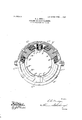
My invention 'is illustrated in the accompanying drawing, which represents a four pole dynamo electric machine, of which F is the field frame, which is split into two parts and bolted together, as shown.
M M M and M represent the main poles of the machine which are energized by the current passing through the coils C C C and C;
v I and I are the interpoles, provided with the coils C and C. It will be seen that there are only two interpoles and that the location of the armature coils is such that the coils of which one portion isbeneath the inter pole I have their other portions in the inter-' polar space between the poles M and M", and the coils which are acted upon by the interpole I have their other portions in the space etween the main poles M and M and it is thus possibleto dispense with interpoles between the main poles M and lVI,and-M and mainpoles, I am able to spacetheir pol'e 'I'a'ces symmetrically around theperiphery of the armature, while their energizing coils and cores are unsymmetrically spaced, thus allowing the coils of the interpoles to be so placed that they do not interfere with the main pole coils, and all the'space between the pole cores may be utilized forwindings if desired. In other words, the spaces between the main polar faces are ,all equal, while the spaces between the main polar cores are unequal and the interpoles are located in the larger inter-core spaces. 'This cannot beatpoles andcoils will allow not only a consider- I tained in the usual form of magnetic circuit 111 wlnch the poles have symn'ietrical tips and 111 the case of some types of motors, such as automobile and railway, where the outside dimensions of the motors must be kept as small as possible," this arrangement of field able saving ofj lnaterial, but a valuable saving in space.
'The figure shown herewith, represents a four pole machine w th two interpoles, but it is evident that this construction may be utilized in-machineswith more or less than four main poles and I do not wish to innit myself; to this particular number of poles or to the specific proportions shown in this figure as variations may be inadefrom the constructionshown herewith, and still come within the scope' of the claims'attached hereto. Another advantage arising from the construction represented is that the standard method of horizontally splitting the frames of railway motors may be retained and still the advancould be made at any desirable angle with the made without splitting, but in one continuens piece; I do not Wish to limit myself to usmg either a-so'lid'or'a split frame, as both Disclaimer in'Lctters Patent No. 856,4l4-2 horizontal and also that the frame could be frames maybe used to advantage as-the' case requires, but when the splitframe-isused, I
prefer to make the splitthrough the, interpolar spaces, whichdo not contain inter= es. c What I claim is':. i
1. A dynamo electric machine havingmain f in presence of two w tnesses.
and interpoles', the main polefaces being'sy n1- metrically spaced about the periphery of the armature while their cores are unsymmetrically spaced, thereby allowing space-.for the coils of'theinterpoles.
Electra-Dynamic company.
to wit:-
[OFFICIAL GAZETTE, April $23, 1912.]
stantially as described.
A- dynamo electric machine having spaces of different extent between the cores of the mam field poles, and-an interpole located in the larger inter-core s ace.
3, A dynamo electric m'ac line having a plurahty of mam poles with unsymmetrically spaced cores, half as many interpoles'located in alternate intercore spaces-the intercore spaces containing interpoles beinglarger than e spaces which-do not contain interpoles, and t 1e polar tips ofthe main poles belng extended in the tllIGC'tlOIl of the adjacent interpole'tosecure a symmetrical arrangement of the. polar faces, subs t antially as described. 1 A. A dynamo electric machine having a plurality of 'mai-n poles and half asmany i11- terpoles, the main pole faces being symmetrically spaced about the armature, and the 1nter-core'spacos containing interpoles being larger than theinter-corc spaces which do not contain interpoles 5. A dynamo electric machine havinga plurality ofimain poles and half as many interpoles located in alternate spaces between the maiirpoles, theffield frame being split through the interpolar spaces which (lo-not contain lnterpoles, the windings of the main poles being unsymmetrically.Larranged so that these windings and" thewindings 01 the inter-poles substantially fill the frame, sub- 6'; A dynamo-electric,machinehavinga plurality of main poles with unsymmetri-cally spaced cores, half asimany'mt'erpoles located in alternate lntercoreispace's, and the vfield frame being. split through the interpolar.
adjacent-into ole to secure a symmetrical" arrangement 0 as described. s a
In testimony whereof I affix my signature,
the polar'faces, substantialh CHARLES A. MUDGE.
Witnesses;
.- I-I. 'HJA PLEGATE,
WILLIAM H. DAVIS.
DISCLAIMER. 856,414.-0kafle.s A; Madge, New "York, N. Y. DYNAMO-ELEGTRIC MACHINE.
Patent dated June 11, 1907, Disclaimer filed "April-13,1912, by the assignee,
Enters this disclaimer with respect to said Letters l atent No. 856,414
T0 that part of the claims in said Letters Patent which is in the following words,
2. A dynamo electric machine having spaces of different extent between the cores of the main field poles, and an interpole located in the larger intercom-space.
Priority Applications (1)
| Application Number | Priority Date | Filing Date | Title |
|---|---|---|---|
| US33182206A US856414A (en) | 1906-08-24 | 1906-08-24 | Dynamo-electric machine. |
Applications Claiming Priority (1)
| Application Number | Priority Date | Filing Date | Title |
|---|---|---|---|
| US33182206A US856414A (en) | 1906-08-24 | 1906-08-24 | Dynamo-electric machine. |
Publications (1)
| Publication Number | Publication Date |
|---|---|
| US856414A true US856414A (en) | 1907-06-11 |
Family
ID=2924869
Family Applications (1)
| Application Number | Title | Priority Date | Filing Date |
|---|---|---|---|
| US33182206A Expired - Lifetime US856414A (en) | 1906-08-24 | 1906-08-24 | Dynamo-electric machine. |
Country Status (1)
| Country | Link |
|---|---|
| US (1) | US856414A (en) |
-
1906
- 1906-08-24 US US33182206A patent/US856414A/en not_active Expired - Lifetime
Similar Documents
| Publication | Publication Date | Title |
|---|---|---|
| US856414A (en) | Dynamo-electric machine. | |
| US1353658A (en) | Dynamo-electric machine | |
| US713604A (en) | Dynamo-electric machine. | |
| US1255400A (en) | Dynamo-electric machine. | |
| US1701362A (en) | Dynamo-electric machine | |
| US1493851A (en) | System of control | |
| US626172A (en) | Sylvania | |
| US767787A (en) | Commutating dynamo-electric machine. | |
| US2354097A (en) | Direct-current motor | |
| US497113A (en) | Otto titus blathy | |
| US1115724A (en) | Dynamo-electric machine. | |
| US565529A (en) | Dynamo-electric machine | |
| US2385670A (en) | Dynamoelectric machine | |
| US515386A (en) | Jonas weiststrom | |
| US688340A (en) | Direct-current dynamo-electric machine. | |
| US418654A (en) | patten | |
| US1318755A (en) | Control system | |
| US643066A (en) | Alternating-current motor. | |
| US399402A (en) | Prevention of sparking in electric generators and motors | |
| US638070A (en) | Dynamo-electric machine. | |
| US656128A (en) | Method of regulating dynamo-electric machines. | |
| US656127A (en) | Dynamo-electric machine. | |
| US643093A (en) | Electric motor. | |
| US788365A (en) | Dynamo-electric machinery. | |
| US859318A (en) | Dynamo-electric machine. |