US856401A - Hose-coupling. - Google Patents
Hose-coupling. Download PDFInfo
- Publication number
- US856401A US856401A US29248105A US1905292481A US856401A US 856401 A US856401 A US 856401A US 29248105 A US29248105 A US 29248105A US 1905292481 A US1905292481 A US 1905292481A US 856401 A US856401 A US 856401A
- Authority
- US
- United States
- Prior art keywords
- section
- coupling
- members
- locking
- pins
- Prior art date
- Legal status (The legal status is an assumption and is not a legal conclusion. Google has not performed a legal analysis and makes no representation as to the accuracy of the status listed.)
- Expired - Lifetime
Links
Images
Classifications
-
- F—MECHANICAL ENGINEERING; LIGHTING; HEATING; WEAPONS; BLASTING
- F16—ENGINEERING ELEMENTS AND UNITS; GENERAL MEASURES FOR PRODUCING AND MAINTAINING EFFECTIVE FUNCTIONING OF MACHINES OR INSTALLATIONS; THERMAL INSULATION IN GENERAL
- F16L—PIPES; JOINTS OR FITTINGS FOR PIPES; SUPPORTS FOR PIPES, CABLES OR PROTECTIVE TUBING; MEANS FOR THERMAL INSULATION IN GENERAL
- F16L37/00—Couplings of the quick-acting type
- F16L37/08—Couplings of the quick-acting type in which the connection between abutting or axially overlapping ends is maintained by locking members
- F16L37/084—Couplings of the quick-acting type in which the connection between abutting or axially overlapping ends is maintained by locking members combined with automatic locking
- F16L37/0841—Couplings of the quick-acting type in which the connection between abutting or axially overlapping ends is maintained by locking members combined with automatic locking by means of a transversally slidable locking member surrounding the tube
-
- Y—GENERAL TAGGING OF NEW TECHNOLOGICAL DEVELOPMENTS; GENERAL TAGGING OF CROSS-SECTIONAL TECHNOLOGIES SPANNING OVER SEVERAL SECTIONS OF THE IPC; TECHNICAL SUBJECTS COVERED BY FORMER USPC CROSS-REFERENCE ART COLLECTIONS [XRACs] AND DIGESTS
- Y10—TECHNICAL SUBJECTS COVERED BY FORMER USPC
- Y10S—TECHNICAL SUBJECTS COVERED BY FORMER USPC CROSS-REFERENCE ART COLLECTIONS [XRACs] AND DIGESTS
- Y10S285/00—Pipe joints or couplings
- Y10S285/918—O-ring
Definitions
- a coupling comprising a cylindrical section, locking members carried therein having their inner ends pivoted in sockets and having hooked outer ends, inwardly extending pins swiveled to said locking members intermediate of their ends passing through said section and adapted to be forced inwardly and forcing the locking members inwardly, substantially as described.
Description
WIT/V55 No.856 ,401. PATEN'IED JUNE11,1907. :B. J. HANNOLD.
HOSE COUPLING.
APPLICATION TILED 1130.19.1005.
2 SHEETS-SHEET 1.
THE NORRIS Psralu cu, wnsmucrau, n. c.
PATENTED JUNE 11, 1907.
E. J. HANNOLD.
HOSE COUPLING.
APPLICATION FILED nc.1e, 1906.
2 SHEETS-SHEET 2.
WITNES UNITED STATES PATENT OFFICE.
ED J. HANNOLD, OF MEXICO, MISSOURI, ASSIGNOR, BY MESNE assiennnn'rs,
TO 0. A. WITHERSPOON, TRUSTEE, OF MEXICO,
MISSOURI.
HOSE-COUPLING.
Specification of Letters Patent.
Patented June 11, 1907.
Application filed December 19, 1905. Serial No. 292,481.
, larly to an automatic coupling.
The object of my invention is to provide a coupling of this character inwhich the locking or securing means is wholly within the coupling, thereby protecting them from injur and having the appearance of a permanent coupling. By this structure it will be seen that the ordinary projections on the outside are dispensed with and also providing a coupling in which the automatic operation thereof is more readily accomplished, and when coupled form a rigid joint.
To this end the invention includes the com- I bination and arrangement of component parts to be hereinafter described, and particularly pointed out in the claims.
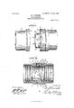
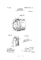
In the accompanying drawings, Figure l is a perspective view of my improved coupling; Fig. 2 1s a longitudinal vertical sectional view of Fig. l; with the sections interlocked. Fig. 3 is a perspective view of the section carrying the hooked members; Fig. 4 is a detail view of one of the hooked members, and Fig. 5 is a detail view of the locking key.
The invention. includes generally male and female sections of the coupling of cylindrical form and carried on the male section a plurality of segmental hook-like members, rocking on balls carried on their inner ends, and
the outer hooked ends adapted to engage an annular shoulder on the opposite or female section.
Referring now to the drawings, 1 represents one section of my coupling and 2 the other section, which, as shown, are of cylindrical form, and have central registeringopenings therein. The inner ends of each section are provided with a thickened portion forming lateral bearing faces 3 and 4, one of which has an annular under cut groove 5 in which is carried a packing ring or gasket 6, adapted to fit into a corresponding annular groove 7 in the bearing face of the opposite section for making a tight joint between the sections. The said thickened portion on the female section 2, forms an abrupt shoulder 8 within the section and over which the hooked end of the locking members pass and lock the two sections together. The said section is also provided within the central opening with an annular flange or projection 9 forming an abutment for the end of the hose to which such section is attached in any well known manner, and the annular recess 10 between the shoulder 8 and said annular flange 9, forms a seat for the hooks 11 of the hooked end of the locking members.
The male section ad'acent to the 011-.
larged lateral bearing face 3 is provided with segmental flanges 12, preferably three innumber as shown, arranged at equal distances apart around the central opening tlnoughthe section. .ln the spaces between said flanges, inwardly extending hook-like members 13 are secured, having their outer ends flush with the outer edge of the rigid flanges, thus forming therewith a continuous annular flange surrounding the central opening in the section. As shown in Fig. 4 of the drawings, these hook-like members, have locking hooks 14 adjacent to their outer ends, and carry on their inner ends a rounded shoulder 15 of about one quarter of the width of the member, which is seated in the annular groove 16 in the cylinder adjacent to the annular flange 17 which forms an abutment for said member and for the hose to which the section is se cured. It will thus be seen that the end of the locking members 13 are carried in a ball and socket joint in which they have a universal rocking motion in the bearing thus formed. The rounded shoulder 15 is locked within the annular groove by the rounded key 18 which is inserted in the said annular groove between the hooked members, and are provided with laterally projecting wings 19, the inner faces of which are rounded forming a convex bearing which. are seated in concave cut-outs 20 in the face of the hooked members, and thus provide means for holding the rounded shoulder 15 within the socket formed by the annular groove and the annular flange 17 and against lateral displacement, and also supplying rounded hearing surfaces on which the said members 14 may rock. It will be appreciated from the foregoing description and the accompanying drawings, that the rounded portions of the end of the locking members l -l forms substantially three-fourths of a circle in cross section, the other one-fourth being occupied in the attachment to the said member, and that the entire rounded portion finds a bearing in the'annular groove 16 and against the annular flange 17, thus allowing a free and wide range of action and at the same time being secured against longitudinal pressure or pulling strain, or lateral displacement. The said rounded key 13 is secured in the groove seat by the obliquely arranged counter-sunk screw 21, which passes through said key and screws into the annular flange 17.
intermediate of their ends, the hook-like members 13 are provided with the conical openings 22 therein, in which are swiveled the pins 23 on the pins 24 inserted in the bore 25 transverse of the said members 13 on the chord of the are formed by each of said members. The said pins 23 extend through openings 26 in the wall of the male section 2, hereinafter more fully described, and have screwed on their opposite free ends nuts 27 adapted to hold them within the openings and movably secure the hook-members 13 against the inner wall of said section and within the longitudinal recesses provided for their accommodation.
The openings 26, before mentioned, comprise conical recesses 29 in the inner wall of the section and central openings commumeating with oppositely positioned circular recesses in the outer wall. The inner conical recess allows more radius of movement to the pins 23 and provide seats for conical-shaped elastic gaskets 31 surrounding the pins 23. The shoulders 32 formed in the openings provide seats for the coil springs 33, interposed between same and the nuts 27 carried on the ends of the pins 23. The heads of the nuts 27 project slightly beyond. the outer wall of the cylindrical section, which is provided with an annular groove 33 forming a guide for a clamp adapted to depress the pins, and
aflord protection to the exposed heads of the nuts 27 from accidental depression.
The exterior of the two sections 1. and 2 of the coupling are substantially alike, and when the hook-members 13 on'the section 2 are forced into the opposite section, they are adapted to beautomatically depressed and pass the shoulder on the opposite section and lock the sections together, and the rigid seg mental flanges thereon bear against the inner face of said shoulder and hold the sections in rigid longitudinal relation and prevent sidewise displacement.
\Vhen the two sections are coupled together, and it is desired to uncouple them, the pins 23 are forced inwardly by pressure on the nuts 27, carrying with them the locking hooks i l, so that the hooks are released from engagement with the shoulder and the two sections may be separated.
Having thus described my invention, what I claim as new and desire to be secured by Letters Patent is I 1. A coupling comprising a cylindrical section, integral segmental flanges arranged at equal distances apart around the opening in said section locking members arranged between said flanges and having their inner ends pivoted in sockets, and having hooked outer ends adapted to interlock with the internal face of an adjoining section, substantially as described.
2. A coupling comprising a cylindrical section, an annular groove and flange within same, locking members having their inner ends seated in said groove and abutting said flange, and a block adapted to lock said members therein, substantially as described.
3. A coupling comprising a cylindrical section, locking members carried therein having their inner ends pivoted in sockets and having hooked outer ends, inwardly extending pins swiveled to said locking members intermediate of their ends passing through said section and adapted to be forced inwardly and forcing the locking members inwardly, substantially as described.
4. A coupling comprising a cylindrical section, an annular groove and flange within same, locking members carried therein, rounded shoulder carried on their inner ends and seated in the annulargroove and abutting the annular flange, rounded blocks carried 111 said groove between the locking members having laterally extending pro ections adapted to secure the said locking members Within the groove, substantially as described.
5. A coupling comprising a cylindrical section, having an enlarged lateral bearing face locking members carried therein having their inner ends pivoted in sockets and having hooked outer ends extending beyond the said bearing face and adapted to interlock with an adjoining section, an annular gasket carried in the bearing'face of the first mentioned section, inwardly extending pins swiveled to said locking members intermediate of their ends passing through said section, nuts carried on the outer end of said pins, a spring surrounding said pin interposed between the nut and shoulder in the opening in the wall of the section, and a gasket surrounding said pin be tween the face of the locking member and the wall of said section, substantially as described.
6. A coupling comprising a cylindrical section, having an enlarged lateral bearing face,
and a central opening through same, segmental flanges adjacent to said opening extending beyond said bearingface, and adapted to extend into an adjoining section, locking members carried in said section between the said segmental flanges, having hooked outer ends flush with the outer ends of said flanges, adapted to enter and interlock with an adjoining section, and their inner ends pivoted in sockets, inwardly-extending pins In testimony whereof I have signed iny sWiVeled to said locking members intermename to this specification in the presence of diate of their ends, springs surrounding same two subscribing Witnesses.
adapted to normally hold said locking IDOIIl- ED J. HANN OLD. ber against the inner Wall of the section and l WVitnesses: in locking coaction With the opposite section, A. C. WVHI'rsoN,
substantially as described. WM. 0. DUGKSTIEN.
Priority Applications (1)
| Application Number | Priority Date | Filing Date | Title |
|---|---|---|---|
| US29248105A US856401A (en) | 1905-12-19 | 1905-12-19 | Hose-coupling. |
Applications Claiming Priority (1)
| Application Number | Priority Date | Filing Date | Title |
|---|---|---|---|
| US29248105A US856401A (en) | 1905-12-19 | 1905-12-19 | Hose-coupling. |
Publications (1)
| Publication Number | Publication Date |
|---|---|
| US856401A true US856401A (en) | 1907-06-11 |
Family
ID=2924856
Family Applications (1)
| Application Number | Title | Priority Date | Filing Date |
|---|---|---|---|
| US29248105A Expired - Lifetime US856401A (en) | 1905-12-19 | 1905-12-19 | Hose-coupling. |
Country Status (1)
| Country | Link |
|---|---|
| US (1) | US856401A (en) |
Cited By (3)
| Publication number | Priority date | Publication date | Assignee | Title |
|---|---|---|---|---|
| US4968440A (en) * | 1988-07-06 | 1990-11-06 | American Cyanamid Company | Coupling element for a filter device |
| US6168574B1 (en) * | 1999-04-01 | 2001-01-02 | Vandemark Ted S. | Massage wand with connecting fitting for spa jet outlet |
| US20060263009A1 (en) * | 2005-05-20 | 2006-11-23 | National Coupling Company, Inc. | Undersea conduit coupling with passageway gate |
-
1905
- 1905-12-19 US US29248105A patent/US856401A/en not_active Expired - Lifetime
Cited By (4)
| Publication number | Priority date | Publication date | Assignee | Title |
|---|---|---|---|---|
| US4968440A (en) * | 1988-07-06 | 1990-11-06 | American Cyanamid Company | Coupling element for a filter device |
| US6168574B1 (en) * | 1999-04-01 | 2001-01-02 | Vandemark Ted S. | Massage wand with connecting fitting for spa jet outlet |
| US20060263009A1 (en) * | 2005-05-20 | 2006-11-23 | National Coupling Company, Inc. | Undersea conduit coupling with passageway gate |
| US7377555B2 (en) * | 2005-05-20 | 2008-05-27 | National Coupling Company, Inc. | Undersea conduit coupling with passageway gate |
Similar Documents
| Publication | Publication Date | Title |
|---|---|---|
| US2867102A (en) | Flexible couplings for shafts | |
| US592899A (en) | Gottfeied n | |
| US856401A (en) | Hose-coupling. | |
| US653143A (en) | Hose-coupling. | |
| US807417A (en) | Coupling. | |
| US966925A (en) | Hose-coupling. | |
| US221153A (en) | Improvement in pipe and hose couplings | |
| US1080674A (en) | Threadless hose-coupling. | |
| US1027579A (en) | Coupling. | |
| US435759A (en) | Dovetail joint | |
| US446176A (en) | John h | |
| US927087A (en) | Universal joint. | |
| US1070233A (en) | Shaft flexible coupling. | |
| US961699A (en) | Train-pipe coupling. | |
| US910687A (en) | Flexible pipe-joint. | |
| US1258639A (en) | Resilient gear. | |
| US409122A (en) | John c | |
| US547073A (en) | Tubular coupling | |
| US439902A (en) | Hose-coupling | |
| US416457A (en) | Separable pulley | |
| US540689A (en) | reams | |
| US1346422A (en) | Hose-coupling | |
| US782595A (en) | Hose-coupling. | |
| US438290A (en) | massey | |
| US672180A (en) | Hose-coupling. |