US8552733B2 - Electrical leak detecting apparatus for an electric vehicle - Google Patents
Electrical leak detecting apparatus for an electric vehicle Download PDFInfo
- Publication number
- US8552733B2 US8552733B2 US12/921,426 US92142609A US8552733B2 US 8552733 B2 US8552733 B2 US 8552733B2 US 92142609 A US92142609 A US 92142609A US 8552733 B2 US8552733 B2 US 8552733B2
- Authority
- US
- United States
- Prior art keywords
- switch
- battery pack
- detection resistor
- voltage
- electrical leak
- Prior art date
- Legal status (The legal status is an assumption and is not a legal conclusion. Google has not performed a legal analysis and makes no representation as to the accuracy of the status listed.)
- Expired - Fee Related, expires
Links
Images


Classifications
-
- G01R31/025—
-
- B—PERFORMING OPERATIONS; TRANSPORTING
- B60—VEHICLES IN GENERAL
- B60L—PROPULSION OF ELECTRICALLY-PROPELLED VEHICLES; SUPPLYING ELECTRIC POWER FOR AUXILIARY EQUIPMENT OF ELECTRICALLY-PROPELLED VEHICLES; ELECTRODYNAMIC BRAKE SYSTEMS FOR VEHICLES IN GENERAL; MAGNETIC SUSPENSION OR LEVITATION FOR VEHICLES; MONITORING OPERATING VARIABLES OF ELECTRICALLY-PROPELLED VEHICLES; ELECTRIC SAFETY DEVICES FOR ELECTRICALLY-PROPELLED VEHICLES
- B60L3/00—Electric devices on electrically-propelled vehicles for safety purposes; Monitoring operating variables, e.g. speed, deceleration or energy consumption
- B60L3/0023—Detecting, eliminating, remedying or compensating for drive train abnormalities, e.g. failures within the drive train
- B60L3/0046—Detecting, eliminating, remedying or compensating for drive train abnormalities, e.g. failures within the drive train relating to electric energy storage systems, e.g. batteries or capacitors
-
- G—PHYSICS
- G01—MEASURING; TESTING
- G01R—MEASURING ELECTRIC VARIABLES; MEASURING MAGNETIC VARIABLES
- G01R31/00—Arrangements for testing electric properties; Arrangements for locating electric faults; Arrangements for electrical testing characterised by what is being tested not provided for elsewhere
- G01R31/50—Testing of electric apparatus, lines, cables or components for short-circuits, continuity, leakage current or incorrect line connections
- G01R31/52—Testing for short-circuits, leakage current or ground faults
-
- G—PHYSICS
- G01—MEASURING; TESTING
- G01R—MEASURING ELECTRIC VARIABLES; MEASURING MAGNETIC VARIABLES
- G01R31/00—Arrangements for testing electric properties; Arrangements for locating electric faults; Arrangements for electrical testing characterised by what is being tested not provided for elsewhere
- G01R31/005—Testing of electric installations on transport means
- G01R31/006—Testing of electric installations on transport means on road vehicles, e.g. automobiles or trucks
Definitions
- the present invention relates to an electrical leak detecting apparatus for an electric vehicle, and more particularly, to an electrical leak detecting apparatus for an electric vehicle, which is capable of not only detecting an electrical leak generated when a vehicle body is connected to the maximum potential or minimum potential of a battery pack, but also detecting which portion of the battery pack the vehicle body is connected to when an electrical leak is generated through the connection of the vehicle body and an intermediate potential of the battery pack.
- Electric vehicles use a high voltage of about 1000 V as a driving source.
- a battery pack that is a driving source of an electric vehicle is separated from a vehicle body and should be maintained in an insulating state from the vehicle body.
- the electric vehicle includes an essential element, such as an electrical leak detecting apparatus for detecting an electrical leak generated when the vehicle body is connected to the battery pack.
- FIG. 1 is a conventional electrical leak detecting apparatus for an electric vehicle 120 .
- the conventional electrical leak detecting apparatus for the electric vehicle 120 illustrated in FIG. 1 is connected between a battery pack 110 and a vehicle body GND and detects an electrical leak generated when the vehicle body GND is connected to the battery pack 110 .
- the conventional electrical leak detecting apparatus for the electric vehicle 120 illustrated in FIG. 1 equalizes a resistor between the electric pack 110 and the vehicle body GND and expresses the equalized resistor as an insulation resistor Rf.
- the resistance value of the insulation resistor Rf is infinity, and current is cut off and does not flow through the conventional electrical leak detecting apparatus for the electric vehicle 120 .
- the resistance value of the insulation resistor Rf is decreased.
- a closed circuit is formed between the battery pack 110 , the insulation resistor Rf, the conventional electrical leak detecting apparatus for the electric vehicle 120 , and the vehicle body GND, respectively, so that current flows through the conventional electrical leak detecting apparatus for the electric vehicle 120 .
- the conventional electrical leak detecting apparatus for the electric vehicle 120 detects an electrical leak between the battery pack 110 and the vehicle body GND by using this principle.
- L is a load that uses a power of the battery pack 110 .
- the conventional electrical leak detecting apparatus for the electric vehicle 120 includes a voltage distribution resistor R s , a detection resistor R m , and a measured potential supply unit V dc , which are connected to one another in series between a minimum potential terminal of the battery pack 110 and the vehicle body GND.
- the conventional electrical leak detecting apparatus for the electric vehicle 120 further includes first and second polarity conversion switches SW 3 and SW 4 between the detection resistor R m and the measured potential supply unit V dc .
- the first and second polarity conversion switches SW 3 and SW 4 are connected to each other and convert the polarity of the measured potential supply unit V dc connected between the battery pack 110 and the vehicle body GND.
- a positive electrode of the measured potential supply unit V dc is connected to the detection resistor R m .
- a negative electrode of the measured potential supply unit V dc is connected to the vehicle body GND, and the battery pack 110 and the measured potential supply unit V dc are connected to each other in a forward direction.
- the negative electrode of the measured potential supply unit V dc is connected to the detection resistor R m .
- the positive electrode of the measured potential supply unit V dc is connected to the vehicle body GND, and the battery pack 110 and the measured potential supply unit V dc are connected in a backward direction.
- the conventional electrical leak detecting apparatus for the electric vehicle 120 equalizes a resistor between the maximum potential terminal of the battery pack 110 and the vehicle body GND and expresses the equalized resistor as a maximum potential insulation resistor Rf 1 .
- Rf 1 a maximum potential insulation resistor
- a closed circuit is formed between the battery pack 110 , the maximum potential insulation resistor Rf 1 , the measured potential supply unit V dc connected to the battery pack 110 in the forward direction, the detection resistor R m , and the voltage distribution resistor R s , respectively, so that current flows through the conventional electrical leak detecting apparatus for the electric vehicle 120 , as illustrated in FIG. 3 .
- the conventional electrical leak detecting apparatus for the electric vehicle 120 measures a both terminal voltage V m of the detection resistor R m to calculate a value of the maximum potential insulation resistor Rf 1 , thereby detecting an electrical leak of the electric vehicle.
- Equation 1 a voltage of the battery pack 110 is expressed in Equation 1 and the following Equations as (V 1 +V 2 ) for better understanding, and the voltage of the battery pack 110 is not limited to (V 1 +V 2 ):
- V m + R m R s + R m + Rf 1 ⁇ ( V 1 + V 2 + V dc ) . Equation ⁇ ⁇ 1
- the value of the maximum potential insulation resistor Rf 1 may be obtained by obtaining (V 1 +V 2 ) that is the voltage of the battery pack 110 . If the expression of the both terminal voltage V m is obtained using only the measured potential supply unit V dc without being affected by (V 1 +V 2 ) that is the voltage of the battery pack 110 , the following operation should be further performed.
- the first and second polarity conversion switches SW 3 and SW 4 of the conventional electrical leak detecting apparatus for the electric vehicle 120 are respectively connected to the b-point, as illustrated in FIG. 4 .
- a closed circuit is formed between the battery pack 110 , the maximum potential insulation resistor Rf 1 , the measured potential supply unit V dc connected to the battery pack 110 in the backward direction, the detection resistor R m , and the voltage distribution resistor R s , respectively, so that current flows through the conventional electrical leak detecting apparatus for the electric vehicle 120 , as illustrated in FIG. 5 .
- the voltage V m as shown in Equation 2 is detected from the detection resistor R m :
- V m - R m R s + R m + Rf 1 ⁇ ( V 1 + V 2 + V d ⁇ ⁇ c ) . Equation ⁇ ⁇ 2
- the conventional electrical leak detecting apparatus for the electric vehicle 120 may measure the both terminal voltage V m easily and precisely.
- Equation 3 When Equation 2 is subtracted from Equation 1 and the result of subtraction is divided by 2, the voltage V m applied to the detection resistor R m is expressed using Equation 3:
- V m R m R s + R m + Rf 1 ⁇ ( V d ⁇ ⁇ c ) .
- the value of the maximum potential insulation resistor Rf 1 equalized by Equation 3 may be obtained using Equation 4.
- the conventional electrical leak detecting apparatus for the electric vehicle 120 may determine an electrical leak by using the resistance value of the equalized maximum potential insulation resistor Rf 1 :
- Rf 1 R m V m ⁇ ( V d ⁇ ⁇ c ) - ( R s + R m ) . Equation ⁇ ⁇ 4
- the conventional electrical leak detecting apparatus for the electric vehicle 120 equalizes a resistor between the minimum potential terminal of the battery pack 110 and the vehicle body GND and expresses the equalized resistor as a minimum potential insulation resistor Rf 2 .
- Rf 2 a minimum potential insulation resistor
- a closed circuit is formed between the voltage distribution resistor R s , the detection resistor R m , the measured potential supply unit V dc connected to the detection resistor R m in a forward direction, and the minimum potential insulation resistor Rf 2 , respectively, so that current flows through the conventional electrical leak detecting apparatus for the electric vehicle 120 , as illustrated in FIG. 7 .
- the conventional electrical leak detecting apparatus for the electric vehicle 120 measures the both terminal voltage V m of the detection resistor R m to calculate a value of the minimum potential insulation resistor Rf 2 , thereby detecting an electrical leak of the electric vehicle.
- the both terminal voltage V m of the detection resistor R m measured by the conventional electrical leak detecting apparatus for the electric vehicle 120 may be expressed using Equation 5:
- V m + R m R s + R m + Rf 2 ⁇ ( + V d ⁇ ⁇ c ) . Equation ⁇ ⁇ 5
- V m - R m R s + R m + Rf 2 ⁇ ( - V d ⁇ ⁇ c ) . Equation ⁇ ⁇ 6
- the both terminal voltage V m measured by the conventional electrical leak detecting apparatus for the electric vehicle 120 may be expressed using Equation 7 by subtracting Equation 6 from Equation 5 and by dividing the result of subtraction by 2.
- the value of the minimum potential insulation resistor Rf 2 equalized by Equation 7 may be calculated using Equation 8.
- the conventional electrical leak detecting apparatus for the electric vehicle 120 may determine an electrical leak by using the value of the equalized minimum potential insulation resistor Rf 2 :
- V m R m R s + R m + Rf 2 ⁇ ( V ⁇ d ⁇ ⁇ c ) , Equation ⁇ ⁇ 7
- Rf 2 R m V m ⁇ ( V d ⁇ ⁇ c ) - ( R s + R m ) . Equation ⁇ ⁇ 8
- the conventional electrical leak detecting apparatus for the electric vehicle 120 detects an electrical leak by using the same method and the same Equation regardless of an electrical leak generated when the vehicle body GND is connected to the maximum potential terminal of the battery pack 110 , an electrical leak generated when the vehicle body GND is connected to the minimum potential terminal of the battery pack 110 , or an electrical leak generated when the vehicle body GND is connected to an intermediate potential of the battery pack 110 . Then, the conventional electrical leak detecting apparatus for the electric vehicle 120 may determine an electrical leak of the battery pack 110 but may not precisely detect a place where an electrical leak is generated.
- the present invention provides an electrical leak detecting apparatus for an electric vehicle, which is capable of not only easily detecting an electrical leak generated when a vehicle body is connected to a battery pack, regardless of a place of the battery pack where the electrical leak is generated, but also detecting the place of the battery pack where the electrical leak is generated.
- an electrical leak detecting apparatus for an electric vehicle, the apparatus including: a first switch and a second switch connected to each other in series between a maximum potential terminal and a minimum potential terminal of a battery pack; a detection resistor having one end connected to a common contact of the first and second switches; and a measured potential supply unit connected between the other end of the detection resistor and a vehicle body and providing a potential to the battery pack.
- the apparatus may further include: a third switch connected between the other end of the detection resistor and the vehicle body and providing the measured potential to the battery pack or cutting off the measured potential from the battery pack; and a fourth switch connected to the third switch in parallel between the other end of the detection resistor and the vehicle body.
- the apparatus may further include: a third switch connected between the other end of the detection resistor and the vehicle body; and a fourth switch connected to the third switch in parallel between the other end of the detection resistor and the vehicle body and providing the measured potential to the battery pack or cutting off the measured potential from the battery pack.
- One of the first switch and the second switch may be turned on and the other one may be turned off, and the measured potential may be provided to the battery pack, and a both terminal voltage of the detection resistor may be measured in such a way that whether an electrical leak is generated when the battery pack is connected to the vehicle body is able to be detected and a place where the electrical leak is generated is able to be detected.
- an electrical leak detecting apparatus for an electric vehicle, the apparatus including: a first switch and a second switch connected to each other in series between a maximum potential terminal and a minimum potential terminal of a battery pack; a detection resistor having one end connected to a common contact of the first and second switches; and a first measured potential supply unit and a second measured potential supply unit providing first and second measured potentials, of different potential, to the battery pack, wherein the first measured potential supply unit or the second measured potential supply unit is connected between the other end of the detection resistor and a vehicle body in parallel, and one of the first measured potential and the second measured potential is provided to the battery pack.
- the first measured potential and the second measured potential may have the same voltage values and opposite polarities.
- the apparatus may further include a third switch providing the first measured potential to the battery pack or cutting off the first measured potential from the battery pack.
- the apparatus may further include a fourth switch providing the second measured potential to the battery pack or cutting off the first measured potential from the battery pack.
- One of the first switch and the second switch may be turned on and the other one may be turned off, and one of the first measured potential and the second measured potential may be provided to the battery pack, and a both terminal voltage of the detection resistor may be measured in such a way that whether an electrical leak is generated when the battery pack is connected to the vehicle body is able to be detected and a place where the electrical leak is generated is able to be detected.
- the apparatus may further include a voltage distribution resistor connected between a maximum potential terminal of the battery pack and the detection resistor.
- the apparatus may further include a voltage distribution resistor connected between a minimum potential terminal of the battery pack and the detection resistor.
- an electrical leak detecting apparatus for an electric vehicle, the apparatus including: a first switch element connected to a positive electrode of a battery pack in parallel; a second switch element not only connected to a negative electrode of the battery pack in parallel but also connected to the first switch element in series; a voltage distribution resistor connected to the first and second switch elements in series; a detection resistor connected between the voltage distribution resistor and a measured potential supply unit in series; the measured potential supply unit and a vehicle body connected to the detection resistor in series; and a ground switch connected between the detection resistor and the vehicle body and grounding the detection resistor and the vehicle body.
- the apparatus may further include first and second polarity conversion switches connecting the measured potential supply unit to the detection resistor and the vehicle body in series.
- the measured potential supply unit may include first and second measured potential supply units which are separated from each other.
- the apparatus may further include: a first measured potential supply unit connection switch connecting a positive electrode of the first measured potential supply unit to the detection resistor and connecting a negative electrode of the first measured potential supply unit to the vehicle body; and a second measured potential supply unit connection switch connecting a negative electrode of the second measured potential supply unit to the detection resistor and connecting a positive electrode of the second measured potential supply unit to the vehicle body.
- a method of detecting an electrical leak for an electric vehicle including: detecting a first voltage of a detection resistor when first and second polarity conversion switches are turned on with a first polarity, a first switch is turned off, a second switch is turned on and a ground switch is turned off; detecting a second voltage of the detection resistor by turning on the ground switch; obtaining a third voltage of the detection resistor by using a measured potential supply unit by subtracting the second voltage of the detection resistor from the first voltage of the detection resistor; detecting a fourth voltage of the detection resistor when the first and second polarity conversion switches are turned on with a second polarity, the first switch is turned on, the second switch is turned off and the ground switch is turned off; detecting a fifth voltage of the detection resistor by turning on the ground switch; obtaining a sixth voltage of the detection resistor by using the measured potential supply unit by subtracting the fifth voltage of the detection resistor from the fourth voltage of the detection resistor; and
- both the third voltage and the sixth voltage of the detection resistor are detected and intermediate potential insulation failure is determined, which portion of the battery pack insulation failure is generated may be detected by comparing the first voltage of the detection resistor with the fourth voltage of the detection resistor.
- FIG. 1 illustrates a conventional electrical leak detecting apparatus for an electric vehicle
- FIGS. 2 through 9 illustrate an operation of the conventional electrical leak detecting apparatus for an electric vehicle illustrated in FIG. 1 ;
- FIG. 10 illustrates an electrical leak detecting apparatus for an electric vehicle, according to an embodiment of the present invention
- FIGS. 11 through 16 illustrate an operation of the electrical leak detecting apparatus for an electric vehicle illustrated in FIG. 10 ;
- FIG. 17 illustrates an electrical leak detecting apparatus for an electric vehicle, according to another embodiment of the present invention.
- FIG. 18 illustrates an electrical leak detecting apparatus for an electric vehicle, according to another embodiment of the present invention.
- FIGS. 19 through 28 illustrate an operation of the electrical leak detecting apparatus for an electric vehicle illustrated in FIG. 18 ;
- FIG. 29 illustrates an electrical leak detecting apparatus for an electric vehicle, according to another embodiment of the present invention.
- FIGS. 30 through 35 illustrate a maximum potential insulation failure mode
- FIGS. 36 through 41 illustrate a minimum potential insulation failure mode
- FIG. 42 illustrates an electrical leak detecting apparatus for an electric vehicle, according to another embodiment of the present invention.
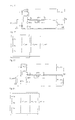
- FIG. 10 illustrates an electrical leak detecting apparatus for an electric vehicle 300 , according to the first embodiment of the present invention.
- the electrical leak detecting apparatus for an electric vehicle 300 is connected between a battery pack 110 and a vehicle body GND and detects whether an electrical leak is generated when the vehicle body GND is connected to the battery pack 110 .
- the electrical leak detecting apparatus for an electric vehicle 300 equalizes a resistor between the maximum potential terminal of the battery pack 110 and the vehicle body GND and expresses the equalized resistor as a maximum potential insulation resistor Rf —pos .
- the electrical leak detecting apparatus for an electric vehicle 300 equalizes a resistor between the minimum potential terminal of the battery pack 110 and the vehicle body GND and expresses the equalized resistor as a minimum potential insulation resistor Rf —neg .
- the electrical leak detecting apparatus for an electric vehicle 300 equalizes a resistor between an intermediate potential of the battery pack 110 and the vehicle body GND and expresses the equalized resistor as an intermediate potential insulation resistor Rf —cell .
- the resistance value of each of the insulation resistors Rf —pos , Rf neg , and Rf —cell is infinity, and current is cut off.
- the electrical leak detecting apparatus for an electric vehicle 300 when an abnormality occurs in the battery pack 110 and an electrical leak is generated when the vehicle body GND is connected to the battery pack 110 , the resistance value of each of the insulation resistors Rf —pos , Rf —neg , and Rf —cell is decreased, and a closed circuit is generated between the battery pack 110 , the corresponding insulation resistor, the electrical leak detecting apparatus for an electric vehicle 300 , and the vehicle body GND.
- the present invention detects an electrical leak of the battery pack 110 and the vehicle body GND by using this principle.
- the electrical leak detecting apparatus for an electric vehicle 300 includes a first voltage distribution resistor Rs 1 connected to the battery pack 110 in parallel, a first switch SW 31 , a second switch SW 32 , a second voltage distribution resistor Rs 2 , a detection resistor R m having one end connected to a common contact of the first and second switches SW 31 and SW 32 , a first measured potential supply unit Vp 1 having a negative electrode connected to the other end of the detection resistor Rm and a positive electrode connected to the vehicle body GND, a second measured potential supply unit Vp 2 having a positive electrode connected to the other end of the detection resistor R m and a negative electrode connected to the vehicle body GND, a third switch SW 33 that provides a switching function between the detection resistor R m and the first measured potential supply unit Vp 1 , and a fourth switch SW 34 that provides a switching function between the detection resistor R m and the second measured potential supply unit Vp 2 .
- one voltage distribution resistor R s may be connected between the common contact of the first and second switches SW 31 and SW 32 and the detection resistor R m .
- the third switch SW 33 is connected to provide a switching function between the first measured potential supply unit Vp 1 and the detection resistor R m .
- the fourth switch SW 34 is connected to provide a switching function between the second measured potential supply unit Vp 2 and the detection resistor R m .
- an additional switch may be connected to the positive and negative electrodes of the first measured potential supply unit Vp 1
- an additional switch may be connected to the positive and negative electrodes of the second measured potential supply unit Vp 2 .
- Voltages of the first measured potential supply unit Vp 1 and the second measured potential supply unit Vp 2 are the same as a measured potential supply unit Vp, and only polarities thereof are connected reversely.
- FIGS. 11 through 16 illustrate an operation of the electrical leak detecting apparatus for an electric vehicle 300 illustrated in FIG. 10 .
- the electrical leak detecting apparatus for an electric vehicle 300 when an electrical leak is generated when the vehicle body GND is connected to the maximum potential terminal of the battery pack 110 will be described.
- the electrical leak is generated when the vehicle body GND is connected to the maximum potential terminal of the battery pack 110
- current flows through the electrical leak detecting apparatus for an electric vehicle 300 via the maximum potential insulation resistor Rf —pos .
- the second switch SW 32 and the fourth switch SW 34 are turned on and the first switch SW 31 and the third switch SW 33 are turned off, in the electrical leak detecting apparatus for an electric vehicle 300 , the second measured potential supply unit Vp 2 is connected to the battery pack 110 in a forward direction, as illustrated in FIG. 11 .
- a closed circuit is formed between the battery pack 110 , the maximum potential insulation resistor Rf —pos , the second measured potential supply unit Vp 2 , the fourth switch SW 34 , the detection resistor R m , the second switch SW 32 , and the second voltage distribution resistor Rs 2 , respectively, so that current flows through the electrical leak detecting apparatus for an electric vehicle 300 .
- the electrical leak detecting apparatus for an electric vehicle 300 measures the both terminal voltage V m of the detection resistor R m .
- the both terminal voltage V m of the detection resistor R m measured by the electrical leak detecting apparatus for an electric vehicle 300 may be expressed using Equation 9:
- V m + R m Rs 2 + R m + Rf _ ⁇ pos ⁇ ⁇ ( V 1 + V 2 + Vp ) . Equation ⁇ ⁇ 9
- a voltage (V 1 +V 2 ) that is a voltage of the battery pack 110 should be obtained in order to obtain the value of the maximum potential insulation resistor Rf —pos by using Equation 9.
- the expression of the both terminal voltage V m is obtained by using only the measured potential supply unit Vp.
- the first measured potential supply unit Vp 1 is connected to the battery pack 110 in a backward direction, and a closed circuit between the battery pack 110 , the maximum potential insulation resistor Rf —pos , the first measured potential supply unit Vp 1 , the third switch SW 33 , the detection resistor Rm, the second switch SW 32 , and the second voltage distribution resistor Rs 2 , respectively, so that current flows through the electrical leak detecting apparatus for an electric vehicle 300 .
- the both terminal voltage V m of the detection resistor R m measured by the electrical leak detecting apparatus for an electric vehicle 300 is expressed using Equation 10:
- V m - R m Rs 2 + R m + Rf _ ⁇ ⁇ p ⁇ ⁇ os ⁇ ( V 1 + V 2 - Vp ) . Equation ⁇ ⁇ 10
- Equation 10 When Equation 10 is subtracted from Equation 9 and the result of subtraction is divided by 2, the both terminal voltage V m of the detection resistor R m is expressed using Equation 11.
- the value of the maximum potential insulation resistor Rf —pos may be obtained as shown in Equation 12 by using Equation 11:
- V m R m Rs 2 + R m + Rf _ ⁇ ⁇ pos ⁇ ( Vp ) , Equation ⁇ ⁇ 11
- Rf _ ⁇ ⁇ pos R m V m ⁇ ( Vp ) - ( Rs 2 + R m ) . Equation ⁇ ⁇ 12
- the electrical leak detecting apparatus for an electric vehicle 300 measures the both terminal voltage V m of the detection resistor R m while turning on the second switch SW 32 and sequentially turning on the fourth switch SW 34 and the third switch SW 33 , thereby obtaining a value of the equalized maximum potential insulation resistor Rf —pos .
- the electrical leak detecting apparatus for an electric vehicle 300 may detect an electrical leak of the electronic vehicle and a place where the electrical leak is generated.
- the electrical leak detecting apparatus for an electric vehicle 300 since, when an electrical leak is generated when the vehicle body GND is connected to the maximum potential terminal of the battery pack 110 , the voltage (V 1 +V 2 ) of the battery pack 110 is applied to the detection resistor R m , a detection sensitivity of the electrical leak detecting apparatus for an electric vehicle 300 is improved so that the both terminal voltage V m of the detection resistor R m may be easily measured.
- the electrical leak detecting apparatus for an electric vehicle 300 when an electrical leak is generated when the vehicle body GND is connected to the minimum potential terminal of the battery pack 110 will be described.
- the electrical leak is generated when the vehicle body GND is connected to the minimum potential terminal of the battery pack 110
- current flows through the electrical leak detecting apparatus for an electric vehicle 300 via the minimum potential insulation resistor Rf —neg .
- the first switch SW 31 and the third switch SW 33 are turned on and the second switch SW 32 and the fourth switch SW 34 are turned off, in the electrical leak detecting apparatus for an electric vehicle 300 , the first measured potential supply unit Vp 1 is connected to the battery pack 110 in a forward direction, as illustrated in FIG. 12 .
- a closed circuit is formed between the battery pack 110 , the first voltage distribution resistor Rs 1 , the first switch SW 31 , the detection resistor R m , the third switch SW 33 , the first measured potential supply unit Vp 1 , and the minimum potential insulation resistor Rf —neg , respectively, so that current flows through the electrical leak detecting apparatus for an electric vehicle 300 .
- the electrical leak detecting apparatus for an electric vehicle 300 measures the both terminal voltage V m of the detection resistor R m .
- the both terminal voltage Vm of the detection resistor R m measured by the electrical leak detecting apparatus for an electric vehicle 300 may be expressed using Equation 13:
- V m + R m Rs 1 + R m + Rf _ ⁇ ⁇ neg ⁇ ( V 1 + V 2 + Vp ) . Equation ⁇ ⁇ 13
- a voltage (V 1 +V 2 ) that is a voltage of the battery pack 110 should be obtained in order to obtain the value of the minimum potential insulation resistor Rf —neg by using Equation 13.
- the expression of the both terminal voltage V m is obtained by using only the measured potential supply unit Vp.
- the second measured potential supply unit Vp 2 is connected to the battery pack 110 in a backward direction. Also, a closed circuit between the battery pack 110 , the first voltage distribution resistor Rs 1 , the first switch SW 31 , the detection resistor R m , the fourth switch SW 34 , the second measured potential supply unit Vp 2 , and the minimum potential insulation resistor Rf —neg , respectively, so that current flows through the electrical leak detecting apparatus for an electric vehicle 300 .
- the both terminal voltage V m of the detection resistor R m measured by the electrical leak detecting apparatus for an electric vehicle 300 is expressed using Equation 14:
- V m - R m Rs 2 + R m + Rf _ ⁇ ⁇ pos ⁇ ( V 1 + V 2 - Vp ) . Equation ⁇ ⁇ 14
- Equation 14 When Equation 14 is subtracted from Equation 13 and the result of subtraction is divided by 2, the both terminal voltage V m of the detection resistor R m measured by the electrical leak detecting apparatus for an electric vehicle 300 is expressed using Equation 15.
- the value of the minimum potential insulation resistor Rf —neg may be obtained as shown in Equation 16 by using Equation 15:
- V m R m Rs 2 + R m + Rf _ ⁇ ⁇ pos ⁇ ( Vp ) , Equation ⁇ ⁇ 15
- Rf _ ⁇ ⁇ pos R m V m ⁇ ( Vp ) - ( Rs 2 + R m ) . Equation ⁇ ⁇ 16
- the electrical leak detecting apparatus for an electric vehicle 300 measures the both terminal voltage V m of the detection resistor R m while turning on the first switch SW 31 and sequentially turning on the third switch SW 33 and the fourth switch SW 34 , thereby obtaining a value of the equalized minimum potential insulation resistor Rf —neg .
- the electrical leak detecting apparatus for an electric vehicle 300 may detect an electrical leak of the electronic vehicle and a place where the electrical leak is generated.
- the electrical leak detecting apparatus for an electric vehicle 300 since, when an electrical leak is generated when the vehicle body GND is connected to the minimum potential terminal of the battery pack 110 , the voltage (V 1 +V 2 ) of the battery pack 110 is applied to the detection resistor R m , a detection sensitivity of the electrical leak detecting apparatus for an electric vehicle 300 is improved so that the both terminal voltage V m of the detection resistor R m may be easily measured.
- the electrical leak detecting apparatus for an electric vehicle 300 when an electrical leak is generated when the vehicle body GND is connected to the intermediate potential of the battery pack 110 will be described.
- the electrical leak detecting apparatus for an electric vehicle 300 obtains a value of intermediate potential insulation resistor Rf —cell in a state where the first switch SW 1 is connected to the maximum potential terminal of the battery pack 110 .
- the electrical leak detecting apparatus for an electric vehicle 300 obtains a value of the intermediate potential insulation resistor Rf —cell in a state where the second switch SW 2 is connected to the minimum potential terminal of the battery pack 110 . Subsequently, the electrical leak detecting apparatus for an electric vehicle 300 calculates a place where an electrical leak is generated, using the ratio of the values obtained in the two cases. This will be described later in detail.
- the electrical leak detecting apparatus for an electric vehicle 300 may obtain the value of the intermediate potential insulation resistor Rf —cell in a similar way to obtaining the value of the maximum potential insulation resistor Rf —pos described with reference to FIG. 11 .
- the second switch SW 32 and the fourth switch SW 34 are turned on and the first switch SW 31 and the third switch SW 33 are turned off, the both terminal voltage V m of the detection resistor R m is expressed as shown in Equation 17.
- Equation 18 When Equation 18 is subtracted from Equation 17 and the result of subtraction is divided by 2, the both terminal voltage V m of the detection resistor R m is expressed as shown in Equation 19 expressed using only the second measured potential supply unit Vp 2 .
- the value of the intermediate potential insulation resistor Rf —cell may be obtained as shown in Equation 20 by using Equation 19:
- V m + R m Rs 2 + R m + Rf _ ⁇ ⁇ cell ⁇ ( V 2 + Vp ) , Equation ⁇ ⁇ 17
- V m - R m Rs 2 + R m + Rf _ ⁇ ⁇ cell ⁇ ( V 2 - Vp )
- V m R m Rs 2 + R m + Rf _ ⁇ ⁇ cell ⁇ ( Vp )
- Rf _ ⁇ ⁇ cell R m V m ⁇ ( Vp ) - ( Rs 2 + R m ) . Equation ⁇ ⁇ 20
- the electrical leak detecting apparatus for an electric vehicle 300 may obtain the value of the intermediate potential insulation resistor Rf —cell in a similar way to obtaining the value of the minimum potential insulation resistor Rf —neg described with reference to FIG. 12 .
- the both terminal voltage V m of the detection resistor R m is expressed as shown in Equation 21.
- Equation 22 When the first switch SW 31 and the fourth switch SW 34 are turned on and the second switch SW 32 and the third switch SW 33 are turned off, the both terminal voltage V m of the detection resistor R m is expressed as shown in Equation 22.
- Equation 22 When Equation 22 is subtracted from Equation 21 and the result of subtraction is divided by 2, the both terminal voltage V m of the detection resistor R m is expressed as shown in Equation 23 expressed using only the first measured potential supply unit Vp 1 .
- the value of the intermediate potential insulation resistor Rf —cell may be obtained as shown in Equation 24 by using Equation 23:
- V m + R m Rs 1 + R m + Rf _ ⁇ ⁇ cell ⁇ ( V 1 + Vp ) , Equation ⁇ ⁇ 21
- V m - R m Rs 1 + R m + Rf _ ⁇ ⁇ cell ⁇ ( V 1 - Vp ) , Equation ⁇ ⁇ 22
- V m - ⁇ R m Rs 1 + R m + Rf _ ⁇ ⁇ cell ⁇ ( Vp ) Equation ⁇ ⁇ 23
- Rf _ ⁇ ⁇ cell R m V m ⁇ ( Vp ) - ( Rs 1 + R m ) . Equation ⁇ ⁇ 24
- the electrical leak detecting apparatus for an electric vehicle 300 when an insulation failure is generated at an intermediate point of the battery pack 110 , a closed circuit is formed regardless of whether the first switch SW 31 is turned on and the second switch SW 32 is turned off or whether the first switch SW 31 is turned off and the second switch SW 32 is turned on, so that current flows through the detection resistor R m .
- the electrical leak detecting apparatus for an electric vehicle 300 may detect that an electrical leak is generated at the intermediate point of the battery pack 110 .
- the detection voltage V m of the detection resistor R m when the second switch SW 32 is connected and the detection voltage V m of the detection resistor R m when the first switch SW 31 is connected are different from each other according to a place where an electrical leak is generated at the intermediate point of the battery pack 110 .
- the electrical leak detecting apparatus for an electric vehicle 300 may detect a place where the electrical leak of the electric vehicle is generated, by using the ratio of the values obtained in the two cases.
- the electrical leak detecting apparatus for an electric vehicle 300 when a complex electrical leak is generated in the battery pack 110 will be described.
- the electrical leak detecting apparatus for an electric vehicle 300 When an electrical leak is generated at all of the maximum potential terminal, the minimum potential terminal, and the intermediate potential of the battery pack 100 , the electrical leak detecting apparatus for an electric vehicle 300 turns on the second switch SW 32 and the fourth switch SW 34 connected to the minimum potential terminal of the battery pack 110 and turns off the first switch SW 31 and the third switch SW 33 .
- the electrical leak detecting apparatus for an electric vehicle 300 may detect the both terminal voltage V m of the detection resistor R m .
- the electrical leak detecting apparatus for an electric vehicle 300 turns on the second switch SW 32 and the third switch SW 33 of the battery pack 110 and turns off the first switch SW 31 and the fourth switch SW 34 so as to remove the effect of (V 1 +V 2 ), like in the previous way.
- the both terminal voltage V m of the detection resistor R m is expressed as shown in Equation 25 in which the voltage of the battery pack 110 is not included, by subtracting a voltage value detected at this time from a voltage value detected immediately before and by dividing the result of subtraction by 2.
- the maximum potential insulation resistor Rf —pos , the minimum potential insulation resistor Rf —neg , and the intermediate potential insulation resistor Rf —cell are connected to one another in parallel.
- An equivalent circuit of the electrical leak detecting apparatus for an electric vehicle 300 is as illustrated in FIG. 16 .
- V m R m Rs 2 + R m + Rf ⁇ _ ⁇ ⁇ total ⁇ ( Vp ) , Equation ⁇ ⁇ 25
- a total potential insulation resistor Rf —total is an equivalent circuit of the maximum potential insulation resistor Rf —pos , the minimum potential insulation resistor Rf —neg , and the intermediate potential insulation resistor Rf —cell , which are connected to one another in parallel.
- the electrical leak detecting apparatus for an electric vehicle 300 obtains a value of the total potential insulation resistor Rf —total by turning on the first switch SW 31 connected to the maximum potential terminal of the battery pack 110 and by expressing the both terminal voltage V m of the detection resistor R m as Equation in which the voltage of the battery pack 110 is not included.
- the electrical leak detecting apparatus for an electric vehicle 300 may detect a failure even when an electrical leak is generated from a complex point of the battery pack 110 .
- FIG. 17 illustrates an electrical leak detecting apparatus for an electric vehicle 300 , according to the second embodiment of the present invention.
- the electrical leak detecting apparatus for an electric vehicle 300 is constituted by omitting the first measured potential supply unit Vp 1 connected between the third switch SW 33 and the vehicle body GND from the electrical leak detecting apparatus for an electric vehicle 300 illustrated in FIG. 10 .
- the first measured potential supply unit Vp 1 is omitted, the same effect as that of FIG. 10 is obtained, which will be described later.
- the both terminal V m of the detection resistor R m may be measured by turning on the second switch SW 32 and the fourth switch SW 34 and by turning off the first switch SW 31 and the third switch SW 33 , and the measured voltage V m is expressed as Equation 26:
- V m + R m Rs 2 + R m + Rf _ ⁇ pos ⁇ ( V 1 + V 2 + Vp ) . Equation ⁇ ⁇ 26
- Equation 27 the both terminal voltage V m of the detection resistor R m measured by turning on the second switch SW 32 and the third switch SW 33 and by turning off the first switch SW 31 and the fourth switch SW 34 is expressed as Equation 27:
- V m - R m Rs 2 + R m + Rf _ ⁇ pos ⁇ ( V 1 + V 2 ) . Equation ⁇ ⁇ 27
- Equation 28 When Equation 27 is subtracted from Equation 26 so as to remove the effect of (V 1 +V 2 ) in Equations 26 and 27, the result of subtraction is expressed as Equation 28:
- V m R m Rs 2 + R m + Rf _ ⁇ pos ⁇ ( Vp ) . Equation ⁇ ⁇ 28
- Equation 29 The both terminal voltage V m of the detection resistor R m measured by turning on the first switch SW 31 and the third switch SW 33 and by turning off the second switch SW 32 and the fourth switch SW 34 is expressed as Equation 29:
- V m + R m Rs 1 + R m + Rf _ ⁇ neg ⁇ ( V 1 + V 2 ) . Equation ⁇ ⁇ 29
- Equation 30 the both terminal voltage V m of the detection resistor R m measured by turning on the first switch SW 31 and the fourth switch SW 34 and by turning off the second switch SW 32 and the third switch SW 33 is expressed as Equation 30:
- V m - R m Rs 1 + R m + Rf _ ⁇ neg ⁇ ( V 1 + V 2 - Vp ) . Equation ⁇ ⁇ 30
- Equation 31 When Equation 30 is subtracted from Equation 29 so as to remove the effect of (V 1 +VD in Equations 29 and 30, the result of subtraction is expressed as Equation 31:
- V m R m Rs 1 + R m + Rf _ ⁇ neg ⁇ ( Vp ) . Equation ⁇ ⁇ 31
- FIG. 17 only the electrical leak detecting apparatus for an electric vehicle 300 from which the first measured potential supply unit Vp 1 is omitted is illustrated. However, even when the second measured potential supply unit Vp 2 connected between the fourth switch SW 34 and the vehicle body GND, instead of the first measured potential supply unit Vp 1 is omitted from the electrical leak detecting apparatus for an electric vehicle 300 , the same effect as that when the first measured potential supply unit Vp 1 is omitted from the electrical leak detecting apparatus for an electric vehicle 300 may be obtained.
- FIG. 18 illustrates an electrical leak detecting apparatus for an electric vehicle 300 , according to the third embodiment of the present invention.
- the electrical leak detecting apparatus for an electric vehicle 300 is constituted by omitting the second measured potential supply unit Vp 2 connected between the fourth switch SW 34 and the vehicle body GND from the electrical leak detecting apparatus for an electric vehicle 300 illustrated in FIG. 10 .
- the second measured potential supply unit Vp 2 is omitted, the same effect as that of FIG. 10 is obtained, which will be described later.
- FIGS. 19 through 28 illustrate an operation of the electrical leak detecting apparatus for an electric vehicle 300 illustrated in FIG. 18 .
- the electrical leak detecting apparatus for an electric vehicle 300 when an electrical leak is generated when the vehicle body GND is connected to the maximum potential terminal of the battery pack 110 will be described.
- the electrical leak detecting apparatus for an electric vehicle 300 turns on the second switch SW 32 and the fourth switch SW 34 and turns off the first switch SW 31 and the third switch SW 33 .
- the electrical leak detecting apparatus for an electric vehicle 300 forms a closed circuit, as illustrated in FIG. 19 .
- a closed circuit is formed between the battery pack 110 , the maximum potential insulation resistor Rf —pos , the measured potential supply unit Vp, the fourth switch SW 34 , the detection resistor R m , the second switch SW 32 , and the second voltage distribution resistor Rs 2 , respectively.
- a both terminal voltage V m i.e., a voltage caused by current that flows through the detection resistor R m , measured by the electrical leak detecting apparatus for an electric vehicle 300 may be expressed as shown in the following Equation 32:
- V m + R m Rs 2 + R m + Rf _ ⁇ pos ⁇ ( V 1 + V 2 ) . Equation ⁇ ⁇ 32
- a voltage (V 1 +V 2 ) that is a voltage of the battery pack 110 should be obtained in order to obtain the value of the maximum potential insulation resistor Rf —pos by using Equation 32.
- the expression of the both terminal voltage V m is obtained by using only the measured potential supply unit Vp.
- the electrical leak detecting apparatus for an electric vehicle 300 turns on the second switch SW 32 and the third switch SW 33 and turns off the first switch SW 31 and the fourth switch SW 34 .
- a closed circuit is formed between the battery pack 110 , the maximum potential insulation resistor Rf —pos , the fourth switch SW 34 , the detection resistor R m , the second switch SW 32 , and the second voltage distribution resistor Rs 2 , respectively, so that current flows through the electrical leak detecting apparatus for an electric vehicle 300 .
- the both terminal voltage V m of the detection resistor R m measured by the electrical leak detecting apparatus for an electric vehicle 300 is expressed using Equation 33:
- V m - R m Rs 2 + R m + Rf _ ⁇ pos ⁇ ( V 1 + V 2 - Vp ) . Equation ⁇ ⁇ 33
- Equation 34 the value of the maximum potential insulation resistor Rf —pos is expressed as shown in Equation 35 by using Equation 34:
- V m R m Rs 2 + R m + Rf _ ⁇ pos ⁇ ( Vp ) , Equation ⁇ ⁇ 34
- Rf _ ⁇ pos R m V m ⁇ ( Vp ) - ( Rs 2 + R m ) . Equation ⁇ ⁇ 35
- the electrical leak detecting apparatus for an electric vehicle 300 measures the both terminal voltage V m of the detection resistor R m while turning on the second switch SW 32 and sequentially turning on the fourth switch SW 34 and the third switch SW 33 , thereby obtaining a value of the equalized maximum potential insulation resistor Rf —pos .
- the electrical leak detecting apparatus for an electric vehicle 300 may detect an electrical leak of the electronic vehicle and a place where the electrical leak is generated.
- the electrical leak detecting apparatus for an electric vehicle 300 since, when an electrical leak is generated when the vehicle body GND is connected to the maximum potential terminal of the battery pack 110 , the voltage (V 1 +V 2 ) of the battery pack 110 is applied to the detection resistor R m , a detection sensitivity of the electrical leak detecting apparatus for an electric vehicle 300 is improved so that the both terminal voltage V m of the detection resistor R m may be easily measured.
- the electrical leak detecting apparatus for an electric vehicle 300 when an electrical leak is generated when the vehicle body GND is connected to the minimum potential terminal of the battery pack 110 , will be described.
- the electrical leak detecting apparatus for an electric vehicle 300 turns on the first switch SW 31 and the third switch SW 33 and turns off the second switch SW 32 and the fourth switch SW 34 .
- the electrical leak detecting apparatus for an electric vehicle 300 forms a closed circuit, as illustrated in FIG. 21 .
- a closed circuit is formed between the battery pack 110 , the minimum potential insulation resistor Rf —neg , the third switch SW 33 , the detection resistor R m , the first switch SW 31 , and the first voltage distribution resistor Rs 1 , respectively, so that current flows through the electrical leak detecting apparatus for an electric vehicle 300 .
- a both terminal voltage V m i.e., a voltage caused by current that flows through the detection resistor R m , detected by the electrical leak detecting apparatus for an electric vehicle 300 is expressed using Equation 36:
- V m R m Rs 1 + R m + Rf _ ⁇ neg ⁇ ( V 1 + V 2 + Vp ) . Equation ⁇ ⁇ 36
- a voltage (V 1 +V 2 ) that is a voltage of the battery pack 110 should be obtained in order to obtain the value of the minimum potential insulation resistor Rf —neg by using Equation 36.
- the expression of the both terminal voltage V m is obtained by using only the measured potential supply unit Vp.
- the electrical leak detecting apparatus for an electric vehicle 300 turns on the the first switch SW 31 and the fourth switch SW 34 and turns off the second switch SW 32 and the third switch SW 33 .
- a closed circuit is formed between the battery pack 110 , the minimum potential insulation resistor Rf —neg , the fourth switch SW 34 , the detection resistor R m , the first switch SW 31 , and the first voltage distribution resistor Rs 1 , respectively, so that current flows through the electrical leak detecting apparatus for an electric vehicle 300 .
- the both terminal voltage V m of the detection resistor R m measured by the electrical leak detecting apparatus for an electric vehicle 300 is expressed using Equation 37:
- V m R m Rs 1 + R m + Rf _ ⁇ neg ⁇ ( V 1 + V 2 ) . Equation ⁇ ⁇ 37
- Equation 38 When Equation 37 is subtracted from Equation 36 so as to obtain the expression of the both terminal voltage V m by using only the measured potential supply unit Vp, the both terminal voltage V m of the detection resistor R m is expressed as shown Equation 38.
- the value of the minimum potential insulation resistor Rf neg may be obtained as shown in Equation 39 by using Equation 38:
- V m R m Rs 1 + R m + Rf _ ⁇ neg ⁇ ( Vp ) , Equation ⁇ ⁇ 38
- Rf _ ⁇ neg R m V m ⁇ ( Vp ) - ( Rs 1 + R m ) . Equation ⁇ ⁇ 39
- the electrical leak detecting apparatus for an electric vehicle 300 measures the both terminal voltage V m of the detection resistor R m while turning on the first switch SW 31 and sequentially turning on the third switch SW 33 and the fourth switch SW 34 , thereby obtaining a value of the equalized minimum potential insulation resistor Rf —neg .
- the electrical leak detecting apparatus for an electric vehicle 300 when an electrical leak is generated when the vehicle body GND is connected to the minimum potential terminal of the battery pack 110 , the electrical leak detecting apparatus for an electric vehicle 300 turns on the second switch SW 32 and the turns off the first switch SW 31 , a circuit is opened with respect to the voltage (V 1 +V 2 ) of the battery pack 110 so that current hardly flows through the detection resistor R m .
- the electrical leak detecting apparatus for an electric vehicle 300 may detect an electrical leak of the electronic vehicle and a place where the electrical leak is generated.
- the electrical leak detecting apparatus for an electric vehicle 300 since, when an electrical leak is generated when the vehicle body GND is connected to the minimum potential terminal of the battery pack 110 , the voltage (V 1 +V 2 ) of the battery pack 110 is applied to the detection resistor R m , a detection sensitivity of the electrical leak detecting apparatus for an electric vehicle 300 is improved so that the both terminal voltage V m of the detection resistor R m may be easily measured.
- the electrical leak detecting apparatus for an electric vehicle 300 when an electrical leak is generated when the vehicle body GND is connected to the intermediate potential terminal of the battery pack 110 , will be described.
- the electrical leak detecting apparatus for an electric vehicle 300 obtains a value of intermediate potential insulation resistor Rf —cell in a state where the first switch SW 1 is connected to the maximum potential terminal of the battery pack 110 .
- the electrical leak detecting apparatus for an electric vehicle 300 obtains a value of the intermediate potential insulation resistor.
- the electrical leak detecting apparatus for an electric vehicle 300 calculates a place where an electrical leak is generated, using the ratio of the values obtained in the two cases. This will be described later in detail.
- the electrical leak detecting apparatus for an electric vehicle 300 sequentially turns on the third switch SW 33 and the fourth switch SW 34 in a state where the first switch SW 31 is turned on.
- the electrical leak detecting apparatus for an electric vehicle 300 may obtain the value of the intermediate potential insulation resistor Rf —cell in a similar way to obtaining the value of the maximum potential insulation resistor Rf —pos described with reference to FIG. 19 .
- Equation 41 When Equation 41 is subtracted from Equation 40, the both terminal voltage V m of the detection resistor R m caused by current that flows through the detection resistor R m may be expressed as shown in Equation 42, using only the measured potential supply unit Vp.
- the value of the intermediate potential insulation resistor Rf —cell may be obtained using in Equation 43.
- an equivalent circuit of the electrical leak detecting apparatus for an electric vehicle 300 is as illustrated in FIG. 24 .
- V m R m Rs 1 + R m + Rf _ ⁇ cell ⁇ ( V 1 + Vp ) , Equation ⁇ ⁇ 40
- V m R m Rs 1 + R m + Rf _ ⁇ cell ⁇ ( V 1 ) , Equation ⁇ ⁇ 41
- V m R m Rs 1 + R m + Rf _ ⁇ cell ⁇ ( Vp )
- Rf _ ⁇ cell R m V m ⁇ ( Vp ) - ( Rs 1 + R m ) . Equation ⁇ ⁇ 43
- the electrical leak detecting apparatus for an electric vehicle 300 connects the second switch SW 32 and sequentially turns on the fourth switch SW 34 and the third switch SW 33 .
- the electrical leak detecting apparatus for an electric vehicle 300 may obtain the value of the intermediate potential insulation resistor Rf —cell in a similar way to obtaining the value of the minimum potential insulation resistor Rf —neg described with reference to FIG. 21 .
- Equation 45 the both terminal voltage V m of the detection resistor R m is expressed as shown in Equation 45.
- Equation 45 is subtracted from Equation 44
- Equation 46 the both terminal voltage V m of the detection resistor R m is expressed as shown in Equation 46 using only the measured potential supply unit Vp.
- the value of the intermediate potential insulation resistor Rf —cell by using this may be obtained as shown in Equation 47.
- the equivalent circuit of the electrical leak detecting apparatus for an electric vehicle 300 is as illustrated in FIG. 26 :
- V m R m Rs 2 + R m + Rf _ ⁇ cell ⁇ ( V 2 ) , Equation ⁇ ⁇ 44
- V m R m Rs 2 + R m + Rf _ ⁇ cell ⁇ ( V 2 - Vp ) , Equation ⁇ ⁇ ⁇ 45
- V m R m Rs 2 + R m + Rf _ ⁇ cell ⁇ ( Vp )
- Rf _ ⁇ cell R m V m ⁇ ( Vp ) - ( Rs 2 + R m ) . Equation ⁇ ⁇ 47
- the electrical leak detecting apparatus for an electric vehicle 300 when an insulation failure is generated at an intermediate point of the battery pack 110 , a closed circuit is formed regardless of whether the first switch SW 31 is turned on and the second switch SW 32 is turned off or whether the first switch SW 31 is turned off and the second switch SW 32 is turned on, so that current flows through the detection resistor R m .
- the electrical leak detecting apparatus for an electric vehicle 300 may detect that an electrical leak is generated at the intermediate point of the battery pack 110 .
- the detection voltage V m of the detection resistor R m when the second switch SW 32 is connected and the detection voltage V m of the detection resistor R m when the first switch SW 31 is connected are different from each other according to a place where an electrical leak is generated at the intermediate point of the battery pack 110 .
- the electrical leak detecting apparatus for an electric vehicle 300 may detect a place where the electrical leak of the electric vehicle is generated, by using the ratio of the values obtained in the two cases.
- the electrical leak detecting apparatus for an electric vehicle 300 when a complex electrical leak is generated in the battery pack 110 When an electrical leak is generated in two or more places among the maximum potential terminal, the minimum potential terminal, and the intermediate potential of the battery pack 110 , current flows through the electrical leak detecting apparatus for an electric vehicle 300 via the corresponding maximum potential insulation resistor Rf —pos the corresponding minimum potential insulation resistor Rf —neg , and the corresponding intermediate potential insulation resistor Rf —cell .
- the electrical leak detecting apparatus for an electric vehicle 300 When an electrical leak is generated at all of the maximum potential terminal, the minimum potential terminal, and the intermediate potential of the battery pack 100 , the electrical leak detecting apparatus for an electric vehicle 300 turns on the second switch SW 32 and the fourth switch SW 34 connected to the minimum potential terminal of the battery pack 110 and turns off the first switch SW 31 and the third switch SW 33 .
- current flows through the electrical leak detecting apparatus for an electric vehicle 300 via the maximum potential insulation resistor Rf —pos , the minimum potential insulation resistor Rf —neg , and the intermediate potential insulation resistor Rf —cell .
- the electrical leak detecting apparatus for an electric vehicle 300 forms a closed circuit, as illustrated in FIG. 27 .
- the both terminal voltage V m of the detection resistor R m may be detected.
- the voltage of the battery pack 100 and the measured voltage V m are derived from Equations with respect to the both terminal voltage V m applied to the detection resistor R m in a state where the second switch SW 32 and the third switch SW 33 are turned on and in a state where the second switch SW 32 and the fourth switch SW 34 are turned on, respectively, by using an overlapping principle.
- Equations with respect to the both terminal voltage V m applied to the detection resistor R m in a state where the second switch SW 32 and the third switch SW 33 are turned on and in a state where the second switch SW 32 and the fourth switch SW 34 are turned on, respectively, by using an overlapping principle.
- the electrical leak detecting apparatus for an electric vehicle 300 turns on the second switch SW 32 and the third switch SW 33 of the battery pack 110 and turns off the first switch SW 31 and the fourth switch SW 34 so as to remove the effect of (V 1 +V 2 ), like in the previous way.
- the both terminal voltage V m of the detection resistor R m is expressed as shown in Equation 48 by subtracting a voltage value detected at this time from a voltage value detected immediately before and by dividing the result of subtraction by 2.
- the maximum potential insulation resistor Rf —pos the minimum potential insulation resistor Rf —neg , and the intermediate potential insulation resistor Rf —cell are connected to one another in parallel.
- An equivalent circuit of the electrical leak detecting apparatus for an electric vehicle 300 is as illustrated in FIG. 28 .
- V m R m Rs 2 + R m + Rf _ ⁇ total ⁇ ( Vp ) , Equation ⁇ ⁇ 48
- a total potential insulation resistor Rf —total is an equivalent circuit of the maximum potential insulation resistor Rf —pos , the minimum potential insulation resistor Rf —neg , and the intermediate potential insulation resistor Rf —cell , which are connected to one another in parallel.
- a value of the total potential insulation resistor Rf —total is expressed as the following Equation 49 in which the voltage of the battery pack 110 is not included, by using the Equation of the both terminal voltage V m of the detection voltage R m .
- Rf _total R m V m ⁇ ( Vp ) - ( Rs 2 + R m ) . Equation ⁇ ⁇ 49
- the electrical leak detecting apparatus for an electric vehicle 300 may obtain the same result even in any failure.
- FIG. 29 illustrates an electrical leak detecting apparatus for an electric vehicle, according to another embodiment of the present invention.
- the electrical leak detecting apparatus for an electric vehicle includes a battery pack 10 , a first switch element SW 1 connected to a positive electrode of the battery pack 10 in parallel, a second switch element SW 2 not only connected to a negative electrode of the battery pack 10 in parallel but also connected to the first switch element SW 1 in series, a detection resistor R m connected to the first and second switch elements SW 1 and SW 2 in series, a measured potential supply unit V dc connected to the detection resistor R m in series, and a ground switch SW 5 connected between the detection resistor R m and a vehicle body GND and grounding the detection resistor R m and the vehicle body GND.
- the electrical leak detecting apparatus for an electric vehicle according to the present invention further includes first and second polarity conversion switches SW 3 and SW 4 connecting the measured potential supply unit V dc to the detection resistor R m and the vehicle body GND.
- a method of detecting an electrical leak by using the electrical leak detecting apparatus for an electric vehicle according to the present invention is in a maximum potential insulation failure detection mode.
- the first and second polarity conversion switches SW 3 and SW 4 are turned on with a, and the first switch SW 1 is turned off, the second switch SW 2 is turned on and a fifth switch SW 5 is turned off, if an insulation resistor R f between the maximum potential of the battery pack 10 and the vehicle body GND is destroyed, a closed circuit as illustrated in FIG. 31 is formed, and a voltage V m as shown in the following Equation 50 is detected from the detection resistor R m .
- V m + R m R s + R m + R f ⁇ ( V 1 + V 2 + V dc ) Equation ⁇ ⁇ 50
- V m ⁇ 0 R m R s + R m + R f ⁇ ( V 1 + V 2 ) . Equation ⁇ ⁇ 51
- V m When Equation 51 is subtracted from Equation 50, V m may be obtained using only the measured potential supply unit V dc , as shown in the following Equation 52.
- V m R m R s + R m + R f ⁇ V dc Equation ⁇ ⁇ 52
- V m + R m R s + R m + R f ⁇ V dc Equation ⁇ ⁇ 53
- the measured potential supply unit V dc is relatively smaller than the voltage of the battery pack 110 , and thus, the actually-detected voltage V m is very small.
- the detection voltage V m is very low in the maximum potential insulation failure detection mode, insulation failure with the minimum potential of the battery pack 10 is not detected but is detected in a minimum potential failure detection mode of the present invention.
- the first and second polarity conversion switches SW 3 and SW 4 are turned on with a, the first switch SW 1 is turned off, the second switch SW 2 is turned on and the fifth switch is turned off, if an insulation resistor R f between an intermediate potential of the battery pack 10 and the vehicle body GND is destroyed, a closed circuit as illustrated in FIG. 34 is formed, and a voltage V m as shown in Equation 54 is detected from the detection resistor R m .
- V m + R m R s + R m + R f ⁇ ( V 2 + V dc ) Equation ⁇ ⁇ 54
- V m ⁇ 0 R m R s + R m + R f ⁇ V 2 Equation ⁇ ⁇ 55
- V m When Equation 55 is subtracted from Equation 54, V m may be obtained using only the measured potential supply unit V dc , as shown in the following Equation 56.
- V m R m R s + R m + R f ⁇ V dc Equation ⁇ ⁇ 56
- the method of detecting an electrical leak by using the electrical leak detecting apparatus for an electric vehicle according to the present invention is in the minimum potential insulation failure detection mode.
- the first and second polarity conversion switches SW 3 and SW 4 are turned on with b, and the first switch SW 1 is turned on, the second switch SW 2 is turned off and a fifth switch SW 5 is turned off, if an insulation resistor R f between the minimum potential of the battery pack 10 and the vehicle body GND is destroyed, a closed circuit as illustrated in FIG. 37 is formed, and a voltage V m as shown in the following Equation 57 is detected from the detection resistor R m .
- V m + R m R s + R m + R f ⁇ ( V 1 + V 2 + V dc ) Equation ⁇ ⁇ 57
- V m may be obtained using only the measured potential supply unit V dc , as shown in the following Equation 59.
- V m R m R s + R m + R f ⁇ V dc Equation ⁇ ⁇ 59
- V m + R m R s + R m + R f ⁇ V dc Equation ⁇ ⁇ 60
- the measured potential supply unit V dc is relatively smaller than the voltage of the battery pack 110 , and thus, the actually-detected voltage V m is very small.
- the detection voltage V m is very low in the minimum potential insulation failure detection mode, insulation failure with the maximum potential of the battery pack 10 is not detected but is detected in the maximum potential failure detection mode of the present invention.
- V m + R m R s + R m + R f ⁇ ( V 1 + V dc ) Equation ⁇ ⁇ 61
- V m ⁇ 0 R m R s + R m + R f ⁇ V 1 Equation ⁇ ⁇ 62
- V m may be obtained using only the measured potential supply unit V dc , as shown in the following Equation 63.
- V m R m R s + R m + R f ⁇ V dc Equation ⁇ ⁇ 63
- the electrical leak detecting apparatus for an electric vehicle may differentiate maximum potential insulation failure, intermediate potential insulation failure or minimum potential insulation failure of the battery pack 10 from each other.
- the electrical leak detecting apparatus for an electric vehicle determines failure detected in the maximum potential insulation failure detection mode as failure of the maximum potential and determines failure detected in the minimum potential insulation failure detection mode as failure of the minimum potential.
- failure of the intermediate potential may be determined, and which portion of intermediate potential failure is generated may be known proportional to values V 1 and V 2 by comparing a detection voltage V m+ in the maximum potential insulation failure detection mode with a detection voltage V m+ in the minimum potential insulation failure detection mode. For example, if the ratio of the values V 1 and V 2 is 2:3, the portion of the intermediate potential failure is generated may be a portion having a voltage of 3 ⁇ 5 from the minimum potential of the battery pack 10 .
- a way to differentiate detecting intermediate potential failure and complex potential failure is to determine potential failure where a detected voltage value is relatively large, as intermediate potential failure. The reason for this is because, if complex failure occurs, current is differentiated from each other by using each failure resistor compared to the case where failure occurs only in the intermediate potential and current flowing through the detection resistor is small and the value of the detected voltage is decreased.
- FIG. 42 illustrates an electrical leak detecting apparatus for an electric vehicle, according to another embodiment of the present invention.
- the electrical leak detecting apparatus for an electric vehicle includes first and second measured potential supply units V dc1 and V dc2 , a first measured potential supply unit connection switch SW 3 that connects a positive electrode of the first measured potential supply unit V dc1 to a detection resistor R m and connects a negative electrode of the first measured potential supply unit V dc1 to a vehicle body GND, and a second measured potential supply unit connection switch SW 4 that connects a negative electrode of the second measured potential supply unit V dc2 to the detection resistor R m and connects a positive electrode of the second measured potential supply unit V dc2 to the vehicle body GND.
- the voltage distribution resistor R s is disposed in a rear end of the first switch SW 1
- the voltage distribution resistor R s may be disposed in a front end of the first switch SW 1 and the second switch SW 2 , respectively.
- the order of the voltage distribution resistor, the detection resistor, the measured power supply source, and the switch, which are connected to one another in series, may be reverse.
- an electrical leak detecting apparatus for an electric vehicle not only an electrical leak generated when a vehicle body is connected to a battery pack, can be easily detected regardless of a place of the battery pack where the electrical leak is generated, but also the place of the battery pack where the electrical leak is generated, can be detected.
Landscapes
- Engineering & Computer Science (AREA)
- Power Engineering (AREA)
- Physics & Mathematics (AREA)
- General Physics & Mathematics (AREA)
- Life Sciences & Earth Sciences (AREA)
- Sustainable Development (AREA)
- Sustainable Energy (AREA)
- Transportation (AREA)
- Mechanical Engineering (AREA)
- Electric Propulsion And Braking For Vehicles (AREA)
- Testing Of Short-Circuits, Discontinuities, Leakage, Or Incorrect Line Connections (AREA)
Abstract
Description
where a total potential insulation resistor Rf—total is an equivalent circuit of the maximum potential insulation resistor Rf—pos, the minimum potential insulation resistor Rf—neg, and the intermediate potential insulation resistor Rf—cell, which are connected to one another in parallel.
where a total potential insulation resistor Rf—total is an equivalent circuit of the maximum potential insulation resistor Rf—pos, the minimum potential insulation resistor Rf—neg, and the intermediate potential insulation resistor Rf—cell, which are connected to one another in parallel.
Claims (17)
Applications Claiming Priority (7)
| Application Number | Priority Date | Filing Date | Title |
|---|---|---|---|
| KR10-2008-0034108 | 2008-04-14 | ||
| KR1020080034108A KR100999852B1 (en) | 2008-04-14 | 2008-04-14 | Electrical leak detecting device for electric vehicle and electrical leak detecting method using same |
| KR10-2008-0119085 | 2008-11-27 | ||
| KR20080119085 | 2008-11-27 | ||
| KR10-2009-0031418 | 2009-04-10 | ||
| KR1020090031418A KR101063771B1 (en) | 2008-11-27 | 2009-04-10 | Leakage detection device for electric vehicles |
| PCT/KR2009/001920 WO2009128641A2 (en) | 2008-04-14 | 2009-04-14 | Electrical leak detecting apparatus for an electric vehicle |
Publications (2)
| Publication Number | Publication Date |
|---|---|
| US20110006777A1 US20110006777A1 (en) | 2011-01-13 |
| US8552733B2 true US8552733B2 (en) | 2013-10-08 |
Family
ID=43426980
Family Applications (1)
| Application Number | Title | Priority Date | Filing Date |
|---|---|---|---|
| US12/921,426 Expired - Fee Related US8552733B2 (en) | 2008-04-14 | 2009-04-14 | Electrical leak detecting apparatus for an electric vehicle |
Country Status (1)
| Country | Link |
|---|---|
| US (1) | US8552733B2 (en) |
Cited By (2)
| Publication number | Priority date | Publication date | Assignee | Title |
|---|---|---|---|---|
| US20120235824A1 (en) * | 2011-03-15 | 2012-09-20 | Automotive Research & Testing Center | Measuring device for measuring insulation resistance of an electric vehicle |
| US20130154656A1 (en) * | 2011-12-19 | 2013-06-20 | Ford Global Technologies, Llc | Battery pack distributed isolation detection circuitry |
Families Citing this family (16)
| Publication number | Priority date | Publication date | Assignee | Title |
|---|---|---|---|---|
| JP5215040B2 (en) * | 2008-05-27 | 2013-06-19 | 株式会社ケーヒン | Earth leakage detection circuit |
| WO2012164073A1 (en) * | 2011-06-01 | 2012-12-06 | Commissariat à l'énergie atomique et aux énergies alternatives | Detection of an insulation defect |
| EP2570289B1 (en) * | 2011-09-16 | 2018-08-15 | Samsung SDI Co., Ltd. | Device for determining the insulation resistance of a high-voltage battery system |
| JP5767077B2 (en) * | 2011-10-24 | 2015-08-19 | 株式会社ケーヒン | Earth leakage detector |
| PL2801837T3 (en) * | 2012-03-26 | 2019-05-31 | Lg Chemical Ltd | Device and method for measuring insulation resistance of battery |
| DE102012204990A1 (en) * | 2012-03-28 | 2013-10-02 | Robert Bosch Gmbh | Circuit arrangement and method for monitoring a potential separation |
| US9341665B2 (en) * | 2012-04-18 | 2016-05-17 | Lear Corporation | Method and apparatus for high voltage isolation monitor for a vehicle |
| DE102014204870A1 (en) * | 2014-03-17 | 2015-09-17 | Continental Automotive Gmbh | Device and method for monitoring electrical insulation in a vehicle electrical system of a vehicle |
| DE102014205877B4 (en) * | 2014-03-28 | 2019-08-22 | Continental Automotive Gmbh | Device and method for monitoring electrical insulation in a vehicle electrical system |
| US10114058B2 (en) | 2014-09-30 | 2018-10-30 | Ford Global Technologies, Llc | System and method for high voltage leakage detection |
| FR3037406B1 (en) | 2015-06-15 | 2017-06-02 | Renault Sas | ELECTRICAL SYSTEM COMPRISING A CIRCUIT FOR DETECTING AN ELECTRIC ISOLATION FAULT |
| KR101991910B1 (en) * | 2016-11-16 | 2019-06-21 | 주식회사 엘지화학 | Apparatus and method for measuring isolation resistance of battery |
| DE102017219016A1 (en) * | 2017-10-24 | 2019-04-25 | Continental Automotive Gmbh | Method for operating a battery sensor and battery sensor |
| KR102672495B1 (en) * | 2019-03-15 | 2024-06-07 | 에스케이온 주식회사 | Apparatus for measuring insulation resistance |
| CN113310647B (en) * | 2021-06-30 | 2022-11-15 | 中国第一汽车股份有限公司 | Method and device for detecting leakage of battery pack, electronic equipment and storage medium |
| CN113777514B (en) * | 2021-09-24 | 2023-06-16 | 重庆电哥科技(集团)有限公司 | Insulation detection circuit, system and method of back-up energy storage system |
Citations (6)
| Publication number | Priority date | Publication date | Assignee | Title |
|---|---|---|---|---|
| US5382946A (en) | 1993-01-08 | 1995-01-17 | Ford Motor Company | Method and apparatus for detecting leakage resistance in an electric vehicle |
| KR19990037526A (en) | 1997-10-30 | 1999-05-25 | 모리시다 요이치 | Electric vehicle leakage detection device |
| KR20030010582A (en) | 2000-02-22 | 2003-02-05 | 산요 덴키 가부시키가이샤 | Circuit for detecting leakage in power supply |
| US6731116B2 (en) * | 2001-08-29 | 2004-05-04 | Omron Corporation | Short-circuit detector |
| US6998819B2 (en) | 2002-05-28 | 2006-02-14 | Ford Global Technologies, Llc | Current leakage detection in high voltage battery pack |
| US7592815B2 (en) * | 2006-06-08 | 2009-09-22 | Sanyo Electric Co., Ltd. | Leakage detection circuit for electric vehicle |
-
2009
- 2009-04-14 US US12/921,426 patent/US8552733B2/en not_active Expired - Fee Related
Patent Citations (8)
| Publication number | Priority date | Publication date | Assignee | Title |
|---|---|---|---|---|
| US5382946A (en) | 1993-01-08 | 1995-01-17 | Ford Motor Company | Method and apparatus for detecting leakage resistance in an electric vehicle |
| KR19990037526A (en) | 1997-10-30 | 1999-05-25 | 모리시다 요이치 | Electric vehicle leakage detection device |
| US6320389B1 (en) | 1997-10-30 | 2001-11-20 | Matsushita Electric Industrial Co., Ltd. | Electric leak detecting apparatus for electric motorcars |
| KR20030010582A (en) | 2000-02-22 | 2003-02-05 | 산요 덴키 가부시키가이샤 | Circuit for detecting leakage in power supply |
| US6700384B2 (en) | 2000-02-22 | 2004-03-02 | Sanyo Electric Co., Ltd. | Circuit for detecting leakage in power supply |
| US6731116B2 (en) * | 2001-08-29 | 2004-05-04 | Omron Corporation | Short-circuit detector |
| US6998819B2 (en) | 2002-05-28 | 2006-02-14 | Ford Global Technologies, Llc | Current leakage detection in high voltage battery pack |
| US7592815B2 (en) * | 2006-06-08 | 2009-09-22 | Sanyo Electric Co., Ltd. | Leakage detection circuit for electric vehicle |
Cited By (4)
| Publication number | Priority date | Publication date | Assignee | Title |
|---|---|---|---|---|
| US20120235824A1 (en) * | 2011-03-15 | 2012-09-20 | Automotive Research & Testing Center | Measuring device for measuring insulation resistance of an electric vehicle |
| US8766653B2 (en) * | 2011-03-15 | 2014-07-01 | Automotive Research & Testing Center | Measuring device for measuring insulation resistance of an electric vehicle |
| US20130154656A1 (en) * | 2011-12-19 | 2013-06-20 | Ford Global Technologies, Llc | Battery pack distributed isolation detection circuitry |
| US9404956B2 (en) * | 2011-12-19 | 2016-08-02 | Ford Global Technologies, Llc | Vehicle with selectable battery pack isolation detection circuitry using precision resistors |
Also Published As
| Publication number | Publication date |
|---|---|
| US20110006777A1 (en) | 2011-01-13 |
Similar Documents
| Publication | Publication Date | Title |
|---|---|---|
| US8552733B2 (en) | Electrical leak detecting apparatus for an electric vehicle | |
| KR101470553B1 (en) | Apparatus and method for measuring isolation resistance of battery | |
| US8766653B2 (en) | Measuring device for measuring insulation resistance of an electric vehicle | |
| US7560935B2 (en) | Ground-fault resistance measurement circuit and ground-fault detection circuit | |
| US10613156B2 (en) | Ground fault detection apparatus | |
| JP5560474B2 (en) | Dielectric breakdown detection circuit | |
| CN101883707B (en) | Electrically driven power steering device | |
| US8884638B2 (en) | Circuit arrangement for monitoring an electrical insulation | |
| US8860426B2 (en) | Insulation state detection circuit for ungrounded power source | |
| US10962597B2 (en) | Measurement apparatus, energy storage apparatus, measurement system, and offset error measurement method | |
| US20140210479A1 (en) | Device for measuring an electric current | |
| KR20130039817A (en) | Circuit for monitoring relay | |
| US20200064388A1 (en) | Ground fault detection apparatus | |
| EP3822109B1 (en) | Ground fault detection device | |
| US20150276842A1 (en) | Diagnostic method for contactor resistance failure | |
| KR20080022486A (en) | Battery total voltage detection and leak detection device | |
| KR101236606B1 (en) | Detecting Apparatus Of Leakage Current For Electric Car | |
| EP3901640B1 (en) | DEVICE FOR MEASURING INSULATION RESISTANCE | |
| KR101322519B1 (en) | Detecting apparatus of short circuit for electric car and detecting method of short circuit using the same | |
| JP4874034B2 (en) | Battery pack for electric vehicles | |
| CN114938661B (en) | Battery system testing methods and apparatus | |
| KR101063771B1 (en) | Leakage detection device for electric vehicles | |
| KR100999852B1 (en) | Electrical leak detecting device for electric vehicle and electrical leak detecting method using same | |
| CN114252712A (en) | Battery pack insulation detection circuit and method and vehicle | |
| KR20140055186A (en) | Apparatus and method for detecting isolation of electric vehicle |
Legal Events
| Date | Code | Title | Description |
|---|---|---|---|
| AS | Assignment |
Owner name: KEFICO CORPORATION, KOREA, REPUBLIC OF Free format text: ASSIGNMENT OF ASSIGNORS INTEREST;ASSIGNORS:PARK, HYUNSEOK;CHO, SEBONG;JEON, YWUNSEOK;REEL/FRAME:024951/0528 Effective date: 20100902 |
|
| STCF | Information on status: patent grant |
Free format text: PATENTED CASE |
|
| FEPP | Fee payment procedure |
Free format text: PAYOR NUMBER ASSIGNED (ORIGINAL EVENT CODE: ASPN); ENTITY STATUS OF PATENT OWNER: LARGE ENTITY |
|
| FPAY | Fee payment |
Year of fee payment: 4 |
|
| MAFP | Maintenance fee payment |
Free format text: PAYMENT OF MAINTENANCE FEE, 8TH YEAR, LARGE ENTITY (ORIGINAL EVENT CODE: M1552); ENTITY STATUS OF PATENT OWNER: LARGE ENTITY Year of fee payment: 8 |
|
| FEPP | Fee payment procedure |
Free format text: MAINTENANCE FEE REMINDER MAILED (ORIGINAL EVENT CODE: REM.); ENTITY STATUS OF PATENT OWNER: LARGE ENTITY |
|
| LAPS | Lapse for failure to pay maintenance fees |
Free format text: PATENT EXPIRED FOR FAILURE TO PAY MAINTENANCE FEES (ORIGINAL EVENT CODE: EXP.); ENTITY STATUS OF PATENT OWNER: LARGE ENTITY |
|
| STCH | Information on status: patent discontinuation |
Free format text: PATENT EXPIRED DUE TO NONPAYMENT OF MAINTENANCE FEES UNDER 37 CFR 1.362 |
|
| FP | Lapsed due to failure to pay maintenance fee |
Effective date: 20251008 |