US8552398B2 - Converter of orbital momentum into spin momentum for the polarization of particle beams - Google Patents
Converter of orbital momentum into spin momentum for the polarization of particle beams Download PDFInfo
- Publication number
- US8552398B2 US8552398B2 US13/715,662 US201213715662A US8552398B2 US 8552398 B2 US8552398 B2 US 8552398B2 US 201213715662 A US201213715662 A US 201213715662A US 8552398 B2 US8552398 B2 US 8552398B2
- Authority
- US
- United States
- Prior art keywords
- particle beam
- spin
- input
- magnetic field
- axis
- Prior art date
- Legal status (The legal status is an assumption and is not a legal conclusion. Google has not performed a legal analysis and makes no representation as to the accuracy of the status listed.)
- Active
Links
Images


Classifications
-
- H—ELECTRICITY
- H01—ELECTRIC ELEMENTS
- H01J—ELECTRIC DISCHARGE TUBES OR DISCHARGE LAMPS
- H01J37/00—Discharge tubes with provision for introducing objects or material to be exposed to the discharge, e.g. for the purpose of examination or processing thereof
- H01J37/26—Electron or ion microscopes; Electron or ion diffraction tubes
-
- H—ELECTRICITY
- H01—ELECTRIC ELEMENTS
- H01J—ELECTRIC DISCHARGE TUBES OR DISCHARGE LAMPS
- H01J3/00—Details of electron-optical or ion-optical arrangements common to two or more basic types of discharge tubes or lamps
- H01J3/02—Electron guns
-
- G—PHYSICS
- G21—NUCLEAR PHYSICS; NUCLEAR ENGINEERING
- G21K—HANDLING OF PARTICLES OR IONISING RADIATION NOT OTHERWISE PROVIDED FOR; IRRADIATION DEVICES; GAMMA RAY OR X-RAY MICROSCOPES
- G21K1/00—Arrangements for handling particles or ionising radiation, e.g. focusing or moderating
- G21K1/16—Arrangements for handling particles or ionising radiation, e.g. focusing or moderating using polarising devices, e.g. for obtaining a polarised beam
-
- H—ELECTRICITY
- H01—ELECTRIC ELEMENTS
- H01J—ELECTRIC DISCHARGE TUBES OR DISCHARGE LAMPS
- H01J37/00—Discharge tubes with provision for introducing objects or material to be exposed to the discharge, e.g. for the purpose of examination or processing thereof
- H01J37/02—Details
- H01J37/04—Arrangements of electrodes and associated parts for generating or controlling the discharge, e.g. electron-optical arrangement or ion-optical arrangement
- H01J37/06—Electron sources; Electron guns
-
- H—ELECTRICITY
- H01—ELECTRIC ELEMENTS
- H01J—ELECTRIC DISCHARGE TUBES OR DISCHARGE LAMPS
- H01J2203/00—Electron or ion optical arrangements common to discharge tubes or lamps
- H01J2203/02—Electron guns
- H01J2203/0296—Spin-polarised beams
-
- H—ELECTRICITY
- H01—ELECTRIC ELEMENTS
- H01J—ELECTRIC DISCHARGE TUBES OR DISCHARGE LAMPS
- H01J2237/00—Discharge tubes exposing object to beam, e.g. for analysis treatment, etching, imaging
- H01J2237/06—Sources
- H01J2237/063—Electron sources
- H01J2237/06383—Spin polarised electron sources
Definitions
- the present invention relates to an apparatus for spin polarizing a particle beam, adapted to process an input particle beam in such a way as to generate an at least partially spin polarized output particle beam.
- the polarization of electrons has been considered for many years to be an impossible task, mainly owing to the failure of methods based on classical mechanics, such as the Stern-Gerlach experiment for ions [1].
- the first methods for producing weakly polarized beams consisted in the use of the asymmetries induced by the spin-orbit coupling in the Mott scattering on a gold foil [1].
- a high polarization is obtained mainly with semiconductor photocathodes, mainly multilayer GaAsP/GaAs structures under stress which are grown on GaP [2].
- the mechanical stress in the semiconductor produces splitting in the valence bands, which promotes electron transitions with a well-defined polarization.
- the light from a laser is diffused on the photocathode to produce a localized emission of polarized electrons, which are thus accelerated to the working conditions.
- the known polarized sources may achieve a brightness of 10 7 A cm ⁇ 2 sr ⁇ 1 and a polarization purity of up to 90% [3]. Whereas for some applications these values may be sufficient, it should be noted that the effective dimensions of the source are of the order of several hundred nanometers, and that the lifetime under DC operation may reach at most 36 hours [3].
- the invention relates to a spin polarization apparatus of the type defined in the introduction, comprising
- the invention further relates to an apparatus for spin polarizing a particle beam, adapted to process an input particle beam in such a way as to generate an at least partially spin polarized output particle beam, comprising
- the invention additionally relates to a method for spin polarizing a particle beam, comprising the following steps:
- the invention also relates to a method for spin polarizing a particle beam, comprising the following steps:
- the invention moreover relates to a method for producing a vortex particle beam, characterized in that it comprises the following steps:
- the present invention provides an apparatus and a method for filtering a particle beam, in particular an electron beam, on the basis of the spin thereof, that is “spin polarizing” the beam by means of non-standard elements of electron optics.
- This filter may be used to create spin polarized particle beams of high brightness with respect to the known techniques.
- the polarization mechanism is based on principles of quantum mechanics and consists in the conversion of the orbital angular momentum into the intrinsic spin polarization.
- a transverse magnetic field homogeneous in the axial direction but space-variant in the radial direction induces a spin inversion and converts the corresponding change in angular spin momentum into an orbital angular momentum (OAM) of said beam, utilizing a difference in geometric phase which originates in the manipulation of the spin.
- OAM orbital angular momentum
- the invention makes it possible to generate a vortex particle beam, which brings an orbital angular momentum. If applied to a non-polarized input beam, the invention makes it possible to realize an efficient spin polarization filter.
- the description which follows refers, for simplicity, to the case in which the invention is applied to electron beams. However, it can be extended to beams of other types of particles, provided that they are provided with magnetic spin momentum, such as neutrons, atoms, ions, etc. In the case of electron beams, the invention can easily be integrated in the components of electron microscopes.
- FIGS. 1 a - d show the magnetic and electric field geometries associated with different topological charge values in a Wien filter of the polarization apparatus according to the invention
- FIGS. 2 a - c show respectively: ( a ) the distribution in the plane xy of the vector potential A z calculated for a quadrupole Wien filter; ( b ) a three-dimensional representation of the quadrupole Wien filter; and ( c ) a representation on an enlarged scale of the central part of the distribution shown in FIG. 2 a;
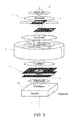
- FIG. 3 shows an example of architecture of an electron microscope provided with a polarization apparatus according to the invention
- FIGS. 4 a - c show respectively: ( a - b ) the transverse profiles of different components of the output electron beam in the far field; ( c ) a possible iris radius used to separate the different components of the electron beam in the apparatus shown in FIG. 3 ; ( d ) the intensity profiles of the components shown in FIGS. 4 a and 4 b;
- FIG. 5 shows a variant of the architecture of an electron microscope shown in FIG. 3 ;
- FIG. 6 shows a further variant of architecture of an electron microscope.
- the invention proceeds from the recent introduction of new diffractive elements of electron optics which make it possible to generate what are known as vortex electron beams, that is electron beams which have a specific orbital angular momentum (OAM) value [5].
- OAM orbital angular momentum
- OAM orbital angular momentum
- a beam of electrons which travel in free space undergoes a “spin-to-orbital angular momentum conversion” (STOC) process in the presence of a space-variant magnetic field. Since the particle electrons are charged, the magnetic field, in addition to acting on the spin, also induces forces which have to be compensated for in order to avoid instances of strong distortion or deflection of the beam. This compensation may be obtained with a suitable electric field, and this led the inventors to conceiving the proposed apparatus as a space-variant Wien filter.
- This apparatus can be utilized to generate vortex electron beams when use is made of a spin polarized beam as input. Conversely, if a pure vortex beam is used as input, produced for example by a holographic method, it is possible to use the STOC process to filter a single spin polarized component of the input beam, as will be shown hereinbelow.
- ⁇ tilde over ( ⁇ ) ⁇ is the spinorial two-component wave function of the electron beam
- e ⁇
- and m are the charge and the mass of the electron
- ⁇ t is the derivative with respect to the time of the time variable t
- /2m being the Bohr magneton, g ⁇ 2 being the g factor of the electron, and ⁇ circumflex over ( ⁇ ) ⁇ ( ⁇ circumflex over ( ⁇ ) ⁇ x , ⁇ circumflex over ( ⁇ ) ⁇ y , ⁇ circumflex over ( ⁇ ) ⁇ z ) being the Pauli matrix vector.
- the full Pauli equation is solved in the paraxial slow-varying-envelope approximation for an input beam having a Gaussian profile and an arbitrary uniform input spin state
- ⁇ in a 1
- the output spin state is, however, given by the following general expression
- ⁇ out a 1 [cos( ⁇ /2)
- This spinorial evolution corresponds to the classical Larmor precession of the spin with the space period ⁇ 1 /2, ⁇ being the total angle of precession.
- equation (2) predicts the occurrence of phase variations of the wave function.
- FIG. 2 b is a three-dimensional schematic representation of the filter; this has in essence an annular structure which surrounds a space region of length L through which the particle beam is intended to cross, coaxially to the z axis.
- Arranged along the circumferential direction of the filter are positive and negative electrodes and the N and S poles for generating the desired fields.
- FIG. 2 c shows a view on an enlarged scale of the central region of the filter.
- the fields have to be determined with a precision of 1 part in 10 4 with respect to the planned values.
- the electrons which travel along a given trajectory meet a constant magnetic field of modulus B 0 (r) and orientation ⁇ ( ⁇ ).
- the spin polarized input electrons with a given initial OAM l passing through the q filter undergo the following transformations:
- the ket indices here specify both the spin state (arrows) and the OAM eigenvalue.
- the input spin again controls the sign of the OAM variation, but the total angular momentum of the beam is not preserved and therefore there is an exchange of angular momentum with the field sources.
- this OAM variation can also be explained as the effect of the spin-related magnetic dipole force which acts on the electrons within the magnetic field gradients.
- spin polarized electron beams of high brightness i.e. spatially coherent
- spin polarized sources can achieve a brightness of 10 7 A cm ⁇ 2 sr ⁇ 1 and a polarization purity of up to 90% [3] (and the source decays over time owing to the damage induced by lasers). It is therefore of interest to analyse the effect of the space-variant q filter on an initially non-polarized electron beam having an arbitrary initial OAM l.
- This input beam may simply be viewed as a statistical mix in which 50% of the electrons are in the state
- the beam After passing through the filter under the tuning conditions, the beam becomes a mix of states
- This spin-OAM correlation can be utilized to realize an effective apparatus for spin polarizing an electron beam. In principle, this apparatus requires essentially four basic elements in sequence, that is:
- FIG. 3 schematically shows an example of architecture of a microscope which is equipped to realize the aforementioned functions.
- the reference numbers indicated hereinbelow are those used in this figure.
- the microscope shown in FIG. 3 therefore comprises a vortex beam generator 1 for imparting orbital angular momentum to the input particle beam Bi (function (i)), which is arranged on the aperture of a first condenser 3 .
- This generator 1 may be realized, for example, as a holographic mask, in particular with a fork-like [5, 10] or spiral-like [11] aperture.
- the electromagnetic field generator 5 is suitable for generating a transverse magnetic field (that is with a component along the zero z axis) in the space region extending along a segment of length L of the z axis; in said space region the transverse magnetic field is homogeneous along the direction of the z axis and space-variant in radial and/or azimuthal direction, in such a way as to change the spin of the particles and attach thereto a plurality of different values of orbital angular momentum in dependence on their input spin values (function (ii)).
- the electromagnetic field generator is suitable for additionally generating a transverse electric field so as to balance the Lorentz force produced by the magnetic field on the particles.
- an apparatus 7 , 9 for separating the components of the beam said apparatus being suitable for spatially separating the particles in dependence on their orbital angular momentum values (functions (iii) and (iv)), in such a way as to obtain the at least partially spin polarized output particle beam Bo.
- This may be obtained by means of diffraction of the particles, through the aperture of a second condenser 7 arranged after the magnetic field generator 5 , and subsequent filtering of the undesirable component(s) through a diaphragm 9 arranged after the second condenser 7 .
- stage (iii) the state
- the apparatus described above can be realized in a relatively simple manner for applications in standard electron beam sources, such as those used in TEM or other types of electron microscopy.
- FIG. 5 shows a variant of the architecture of the electron microscope shown in FIG. 3 .
- the elements corresponding to those in the example shown in FIG. 3 have been denoted by the same numerals, and will not be described further.
- the architecture in FIG. 5 differs from the preceding architecture in that it does not have the balanced Wien filter.
- the electromagnetic field generator 5 is suitable for generating a transverse magnetic field (that is with a component along the zero z axis) in the space region extending along a segment of length L of the z axis; in said space region the transverse magnetic field is homogeneous along the direction of the z axis and space-variant in radial and/or azimuthal direction, in such a way as to change the spin of the particles and attach thereto a plurality of different values of orbital angular momentum in dependence on their input spin values (that is function (ii) indicated above).
- a transverse magnetic field that is with a component along the zero z axis
- the electromagnetic field generator 5 ′ is not suitable for generating a transverse electric field to balance the Lorentz force produced by the magnetic field on the particles. Without the balancing of the electric field, the magnetic field introduces undesirable astigmatic aberrations into the beam.
- a second electromagnetic field generator 6 ′ is present after the electromagnetic field generator 5 ′, arranged coaxially to the first electromagnetic field generator 5 ′ and having the same geometry (same number of poles) as the first electromagnetic field generator 5 ′, but with an inverted pole arrangement.
- a transverse magnetic field equal to but of opposing sign with respect to the transverse magnetic field generated by the electromagnetic field generating means 5 ′.
- the aperture of a second condenser 7 is placed after the first electromagnetic field generator 5 ′; in the architecture shown in FIG. 5 , however, this aperture is arranged in such a way as to precede the second electromagnetic field generator 6 ′.
- This variant could be advantageously implemented in a last-generation electron microscope, utilizing the lenses themselves of the electron microscope (with hexapoles for the correction of the aberrations) without adding new elements, on the one hand for producing a variation in the spin of the particles and on the other hand for correcting the astigmatic aberrations.
- the disadvantage of the variant in question is that it introduces instability of the beam so as not to allow for strong fields and therefore strong polarizations.
- the Wien filter used in the embodiment shown in FIG. 3 could give rise to temporal coherence problems; the non-monochromaticity of the current electron beams has the effect that a filter compensated (
- V
- a filter compensated
- V
- V
- Another way consists in removing the electric field; in this case there would be a lesser dependence on the temporal coherence (monochromaticity), but with possible problems relating to astigmatic aberrations discussed above.
- FIG. 6 schematically shows an example of architecture of a microscope realized according to this configuration variant. The same reference numerals have been used for elements corresponding to those shown in FIG. 3 .
- the microscope shown in FIG. 6 therefore comprises an electromagnetic field generator 5 arranged after the aperture of a first condenser 3 .
- the electromagnetic field generator 5 is suitable for generating a transverse magnetic field (that is with a component along the zero z axis) in the space region extending along a segment of length L of the z axis; in said space region the transverse magnetic field is homogeneous along the direction of the z axis and space-variant in radial and/or azimuthal direction, in such a way as to change the spin of the particles and attach thereto a plurality of different values of orbital angular momentum in dependence on their input spin values (function (ii)).
- the electromagnetic field generator also generates a transverse electric field so as to balance (completely or partially) the Lorentz force produced by the magnetic field on the particles.
- a holographic mask 1 ′′ in particular with a fork-like or spiral-like aperture, is arranged after the first electromagnetic field generator 5 .
- the holographic mask 1 ′′ is similar to the vortex beam generator described with reference to the embodiment shown in FIG. 3 .
- the particle beam leaving the electromagnetic field generator 5 is separated diffractively into a central beam and a pair of satellite beams.
- FIG. 6 shows the diffraction nodes N 0 , N 1 and N 2 produced respectively by these beams on an image plane. It can be shown that the central part of the satellite beams N 1 and N 2 is polarized, with opposing polarization between one beam and the other.
- a separating apparatus 7 ′′ for collecting one of the satellite beams and removing a peripheral portion therefrom, in such a way as to obtain the at least partially spin polarized output particle beam Bo. This can be obtained through the aperture of a condenser arranged after the holographic mask, this aperture being coupled to one of the satellite beams and being dimensioned in such a way as to remove a peripheral fraction therefrom.
- this latter architecture could make it possible to achieve simple commutation between the two polarizations, by simply selecting the satellite beam to be taken. Also possible are polarization measures based on the interference between the two satellite beams.
Landscapes
- Chemical & Material Sciences (AREA)
- Analytical Chemistry (AREA)
- Physics & Mathematics (AREA)
- Spectroscopy & Molecular Physics (AREA)
- Engineering & Computer Science (AREA)
- General Engineering & Computer Science (AREA)
- High Energy & Nuclear Physics (AREA)
- Electron Tubes For Measurement (AREA)
- Analysing Materials By The Use Of Radiation (AREA)
- Particle Accelerators (AREA)
- Electron Beam Exposure (AREA)
Abstract
Description
-
- vortex beam generating means for imparting orbital angular momentum to said input particle beam;
- electromagnetic field generating means for generating a transverse magnetic field in a space region extending along a segment of the z axis of the input particle beam, in said space region the transverse magnetic field being homogeneous along the direction of the z axis and space-variant in radial and/or azimuthal direction, in such a way as to change the spin of the particles and attach thereto a plurality of different values of orbital angular momentum in dependence on their input spin values; and
- beam component separating means for spatially separating the particles in dependence on their orbital angular momentum values, in such a way as to obtain said at least partially spin polarized output particle beam.
-
- electromagnetic field generating means for generating a transverse magnetic field in a space region extending along a segment of the z axis of the input particle beam, in said space region the transverse magnetic field being homogeneous along the direction of the z axis and space-variant in radial and/or azimuthal direction, in such a way as to change the spin of the particles and attach thereto a plurality of different values of orbital angular momentum in dependence on their input spin values;
- a holographic mask for diffractively separating the particle beam into a central beam and a pair of satellite beams, and
- separating means for collecting at least one of the satellite beams and removing a peripheral portion therefrom, in such a way as to obtain the at least partially spin polarized output particle beam.
-
- providing an input particle beam;
- imparting an orbital angular momentum to said input particle beam;
- in a space region extending along a segment of the z axis of the input particle beam, subjecting said input particle beam to a transverse magnetic field homogeneous along the direction of the z axis and space-variant in radial and/or azimuthal direction, in such a way as to change the spin of the particles and attach thereto a plurality of different values of orbital angular momentum in dependence on their input spin values; and
- spatially separating the particles in dependence on their orbital angular momentum values, in such a way as to obtain an at least partially spin polarized output particle beam.
-
- providing an input particle beam;
- in a space region extending along a segment of the z axis of the input particle beam, subjecting said input particle beam to a transverse magnetic field homogeneous along the direction of the z axis and space-variant in radial and/or azimuthal direction, in such a way as to change the spin of the particles and attach thereto a plurality of different values of orbital angular momentum in dependence on their input spin values;
- diffractively separating the particle beam into a central beam and a pair of satellite beams, and
- collecting at least one of the satellite beams and removing a peripheral portion therefrom, in such a way as to obtain the at least partially spin polarized output particle beam.
-
- providing a spin polarized input particle beam; and
- in a space region extending along a segment of the z axis of the input particle beam, subjecting said input particle beam to a transverse magnetic field homogeneous along the direction of the z axis and space-variant in radial and/or azimuthal direction, in such a way as to impart to said particle beam an orbital angular momentum in dependence on the particle spin.
where {tilde over (ψ)} is the spinorial two-component wave function of the electron beam, e=−|e| and m are the charge and the mass of the electron, ∂t is the derivative with respect to the time of the time variable t,
is the magnetic momentum of the electron, with μB=ℏ|e|/2m being the Bohr magneton, g≅2 being the g factor of the electron, and {circumflex over (ρ)}=({circumflex over (ρ)}x, {circumflex over (ρ)}y, {circumflex over (ρ)}z) being the Pauli matrix vector.
|ψ
where δ=4πL/Λ1 and Λ1=8πRc/g≅4Λ2. This spinorial evolution corresponds to the classical Larmor precession of the spin with the space period Λ1/2, δ being the total angle of precession. However, in addition to the spin precession, equation (2) predicts the occurrence of phase variations of the wave function. In particular, for an input spin state |↑
α(r,φ,z)=qφ+β (3)
where q is a non-zero integer and β a constant. It is clear that such a field pattern has to have a singularity of topological charge q at r=0. In particular, by imposing the cancellation of the divergence of the field, it is found that the radial factor B0(r)˜r−q, that is the field is cancelled out on the z axis for q<0, whereas it diverges for q>0. In the latter case, there has to be a field source on the axis. Hereinbelow, for simplicity “q filter” denotes a balanced Wien filter, the magnetic field distribution of which in the plane transverse to the beam obeys the equation (3). The electric field will assume an expression identical to that of the magnetic field, with the exception of a rotation of π/2, to balance the Lorentz force: E(r, φ, z)=E0(r)(sin α(φ),−cos α(φ),0). Some examples of field distributions for the q filter are shown in
|↑,l
|↓,l
where the ket indices here specify both the spin state (arrows) and the OAM eigenvalue.
- [1] O. Darrigol Historical Studies in the Physical Sciences, Vol. 15, No. 1 (1984), pp. 39-79
- [2] Y. C. Chao et al., Journal of Physics: Conference Series 299, 012015 (2011)
- [3] N. Yamamoto et al., J. Phys.: Conf. Ser. 298, 012017 (2011)
- [4] S. McGregor et al., J. Phys. 13, 065018 (2011)
- [5] J. Verbeeck et al., Nature 467, 301 (2010)
- [6] K. Y. Bliokh et al., Phys. Rev. Lett. 99, 190404 (2007)
- [7] H. Rose, Optik 32, 144 (1970)
- [8] J. Zach et al., Nucl. Instr. And Meth. A 363, 316 (1995)
- [9] M. R. Scheinfein, Optik 82, 99 (1989)
- [10] B. J. McMorran et al., Science 331, 192 (2011)
- [11] J. Verbeeck et al., Ultramicroscopy (2011), doi: 10.1016/j.ultramic.2011.10.008
Claims (12)
B(r,φ,z)=B 0(r)(cos α(φ), sin α(φ),0),
α(r,φ,z)=qφ+β,
E(r,φ,z)=E 0(r)(sin α(φ),−cos α(φ),0),
α(r,φ,z)=qφ+β,
B(r,φ,z)=B 0(r)(cos α(φ), sin α(φ),0),
α(r,φ,z)=qφ+β,
E(r,φ,z)=E 0(r)(sin α(φ),−cos α(φ),0),
α(r,φ,z)=qφ+β,
Applications Claiming Priority (3)
| Application Number | Priority Date | Filing Date | Title |
|---|---|---|---|
| ITTO2011A1161 | 2011-12-16 | ||
| IT001161A ITTO20111161A1 (en) | 2011-12-16 | 2011-12-16 | ORBITAL MOMENT CONVERTER AT THE TIME OF SPIN FOR THE POLARIZATION OF PARTICLE BANDS |
| ITTO2011A001161 | 2011-12-16 |
Publications (2)
| Publication Number | Publication Date |
|---|---|
| US20130168577A1 US20130168577A1 (en) | 2013-07-04 |
| US8552398B2 true US8552398B2 (en) | 2013-10-08 |
Family
ID=45541014
Family Applications (1)
| Application Number | Title | Priority Date | Filing Date |
|---|---|---|---|
| US13/715,662 Active US8552398B2 (en) | 2011-12-16 | 2012-12-14 | Converter of orbital momentum into spin momentum for the polarization of particle beams |
Country Status (3)
| Country | Link |
|---|---|
| US (1) | US8552398B2 (en) |
| EP (1) | EP2605266A3 (en) |
| IT (1) | ITTO20111161A1 (en) |
Cited By (1)
| Publication number | Priority date | Publication date | Assignee | Title |
|---|---|---|---|---|
| US11402445B2 (en) | 2015-10-27 | 2022-08-02 | Hosein Majlesi | Electron intrinsic spin analyzer |
Families Citing this family (8)
| Publication number | Priority date | Publication date | Assignee | Title |
|---|---|---|---|---|
| JP6245715B2 (en) * | 2014-10-09 | 2017-12-13 | 国立大学法人名古屋大学 | Spin-polarized electron beam coherence measurement device and method of using the same |
| CN105738643B (en) * | 2016-02-03 | 2018-10-30 | 中国人民解放军装备学院 | A kind of flying body method for measuring angular velocity rotating Doppler effect based on vortex light |
| US9960008B2 (en) * | 2016-06-23 | 2018-05-01 | University Of Oregon | Methods and devices for measuring orbital angular momentum states of electrons |
| JP6844777B2 (en) * | 2017-04-28 | 2021-03-17 | 国立研究開発法人理化学研究所 | Holography reproduction method and program |
| RU2699760C1 (en) * | 2018-12-13 | 2019-09-10 | Федеральное государственное бюджетное учреждение "Петербургский институт ядерной физики им. Б.П. Константинова Национального исследовательского центра "Курчатовский институт" (НИЦ "Курчатовский институт-ПИЯФ) | Neutron supermirror polariser |
| CN110501707B (en) * | 2019-08-27 | 2021-07-02 | 中国人民解放军国防科技大学 | Electromagnetic Vortex Imaging Method Based on Orbital Angular Momentum Dual-modal Multiplexing |
| CN114355499B (en) * | 2022-02-24 | 2023-11-17 | 哈尔滨工程大学 | Method for generating transverse spin angular momentum by unpolarized light |
| CN121091345B (en) * | 2025-11-07 | 2026-02-24 | 厦门稀土材料研究所 | Real-time radiation monitoring system for accelerator solid target beam uniformity |
Citations (3)
| Publication number | Priority date | Publication date | Assignee | Title |
|---|---|---|---|---|
| US3214683A (en) * | 1960-03-25 | 1965-10-26 | Trw Inc | Optically pumped gyromagnetic apparatus |
| US5523572A (en) | 1991-05-02 | 1996-06-04 | Daido Tokushuko Kabushiki Kaisha | Process of emitting highly spin-polarized electron beam and semiconductor device therefor |
| US20080210868A1 (en) | 2007-03-01 | 2008-09-04 | Hitachi, Ltd. | Transmission electron microscope |
-
2011
- 2011-12-16 IT IT001161A patent/ITTO20111161A1/en unknown
-
2012
- 2012-12-14 US US13/715,662 patent/US8552398B2/en active Active
- 2012-12-14 EP EP12197283.0A patent/EP2605266A3/en not_active Withdrawn
Patent Citations (3)
| Publication number | Priority date | Publication date | Assignee | Title |
|---|---|---|---|---|
| US3214683A (en) * | 1960-03-25 | 1965-10-26 | Trw Inc | Optically pumped gyromagnetic apparatus |
| US5523572A (en) | 1991-05-02 | 1996-06-04 | Daido Tokushuko Kabushiki Kaisha | Process of emitting highly spin-polarized electron beam and semiconductor device therefor |
| US20080210868A1 (en) | 2007-03-01 | 2008-09-04 | Hitachi, Ltd. | Transmission electron microscope |
Non-Patent Citations (16)
| Title |
|---|
| Bliokh, K. et al. "Semiclassical Dynamics of Electron Wave Packet States with Phase Vortices", Physical Review Letters, 99: 190404-1-190404-4, 2007. |
| Chao, Y. et al. "CEBAF Accelerator Achievements", Journal of Physics: Conference Series, 299: 1-18, 2011. |
| Darrigol, O. "A History of the Question: Can Free Electrons be Polarized", Historical Studies in the Physical Sciences, 15(1): 39-79, 1984. |
| Italian Search Report for corresponding Italian Patent Application No. TO2011A001161 mailed Sep. 14, 2012. |
| McGregor, S. et al. "Transverse quantum Sterm-Gerlach magnets for electrons", New Journal of Physics, 13: 1-17, 2011. |
| McMorran, B. et al. "Electron Laguerre-Gaussian beams", Lasers and Electro-Optics (CLEO), Laser Science and Photonic Applications-CLEO:2011-Laser Science to Photonic Applications, May 1-6, 2011, Baltimore, MD, pp. 1-2. |
| McMorran, B. et al. "Electron Vortex Beams with High Quanta of Orbital Angular Momentum", Science, 331: 192-195, 2011. |
| Rose, H. et al. "Aberration Correction in Electron Microscopy", Proceedings of 2005 Particle Accelerator Conference, Knoxville, Tennessee, pp. 44-48, 2005. |
| Scheinfein, M. "Second order transfer matrices for inhomogeneous field Wien filters including spin-precession", Optik, 82(3): 99-113, 1989. |
| Uchida, M. et al. "Generation of electron beams carrying orbital angular momentum" Nature, vol. 464, No. 7280, Apr. 1, 2010, pp. 737-739. |
| Verbeeck, J. "Atomic scale electron vortices for nanoresearch", Applied Physics Letters, vol. 99, No. 20, Jan. 1, 2011, pp. 203109. |
| Verbeeck, J. et al. "A new way of producing electron vortex probes for STEM", Ultramicroscopy, vol. 113, Feb. 1, 2012, pp. 83-87. |
| Verbeeck, J. et al. "Production and application of electron vortex beams", Nature, vol. 467, No. 7313, Sep. 16, 2010, pp. 301-304. |
| Wang, Y. et al. "Bessel-Gaussian electron beams of cylindrically symmetric spin polarization: Electron beams of cylindrically symmetric spin polarization", Europhysics Letters: A Letters Journal Exploring the Frontiers of Physics, Institute of Physics Publishing, Bristol, France, vol. 95, No. 4, Jul. 26, 2011, pp. 44001. |
| Yamamoto, N. et al. "Status of the high brightness polarized electron source using transmission photocathode", Journal of Physics: Conference Series, 298: 1-6, 2011. |
| Zach, J. et al. "Aberration correction in a low voltage SEM by a multipole corrector", Nuclear Instruments & Methods in Physics Research, Section A, 363:316-325, 1995. |
Cited By (1)
| Publication number | Priority date | Publication date | Assignee | Title |
|---|---|---|---|---|
| US11402445B2 (en) | 2015-10-27 | 2022-08-02 | Hosein Majlesi | Electron intrinsic spin analyzer |
Also Published As
| Publication number | Publication date |
|---|---|
| EP2605266A2 (en) | 2013-06-19 |
| ITTO20111161A1 (en) | 2013-06-17 |
| US20130168577A1 (en) | 2013-07-04 |
| EP2605266A3 (en) | 2015-12-30 |
Similar Documents
| Publication | Publication Date | Title |
|---|---|---|
| US8552398B2 (en) | Converter of orbital momentum into spin momentum for the polarization of particle beams | |
| Karimi et al. | Spin-to-Orbital Angular Momentum Conversion and Spin-Polarization Filtering<? format?> in Electron Beams | |
| Rose | Optics of high-performance electron microscopes | |
| JP5623719B2 (en) | Chromatic aberration correction apparatus and method for correcting charged particle beam apparatus | |
| Mueller et al. | Design of an electron microscope phase plate using a focused continuous-wave laser | |
| JP6276101B2 (en) | Multipole lens, aberration correction device, and electron microscope | |
| JP2004303547A (en) | Electron beam device with aberration corrector | |
| Rose | Outline of an ultracorrector compensating for all primary chromatic and geometrical aberrations of charged-particle lenses | |
| JP6054730B2 (en) | Chromatic aberration correction apparatus and electron microscope | |
| JP6324241B2 (en) | Charged particle beam apparatus and aberration corrector | |
| Valialshchikov et al. | Narrow bandwidth gamma comb from nonlinear Compton scattering using the polarization gating technique | |
| JPS5978432A (en) | Device with deflecting objective system for forming multikind particle beam | |
| WO2016003513A2 (en) | Coherent electron and radiation production using transverse spatial modulation and axial transfer | |
| Karimi et al. | Generation of a spin-polarized electron beam by multipole magnetic fields | |
| Uesugi et al. | Crossed ponderomotive lenses for spherical aberration correction in electron optics | |
| US6797962B1 (en) | Electrostatic corrector for eliminating the chromatic aberration of particle lenses | |
| Plies et al. | The Wien filter: History, fundamentals and modern applications | |
| Wu et al. | Dynamic aperture study for the Duke FEL storage ring | |
| JP5934517B2 (en) | Chromatic aberration corrector and control method for chromatic aberration corrector | |
| Moloney et al. | Ion-optical review of the new Melbourne two-stage microprobe | |
| Hussein et al. | Optimization of an electrostatic quadrupole doublet focusing systems | |
| Tsuno | Monochromators in electron microscopy | |
| Tsuno et al. | Application of Wien filters to electrons | |
| Luo et al. | Evaluation of an elliptically polarized undulator for the future Taiwan Photon Source | |
| JP5666227B2 (en) | Chromatic aberration correction beam deflector, chromatic aberration correction beam separator, charged particle device, method of operating chromatic aberration correction beam deflector, and method of operating chromatic aberration correction beam separator |
Legal Events
| Date | Code | Title | Description |
|---|---|---|---|
| AS | Assignment |
Owner name: CONSIGLIO NAZIONALE DELLE RICERCHE, ITALY Free format text: ASSIGNMENT OF ASSIGNORS INTEREST;ASSIGNORS:GRILLO, VINCENZO;MARRUCCI, LORENZO;KARIMI, EBRAHIM;AND OTHERS;SIGNING DATES FROM 20121227 TO 20130122;REEL/FRAME:029965/0558 |
|
| STCF | Information on status: patent grant |
Free format text: PATENTED CASE |
|
| FPAY | Fee payment |
Year of fee payment: 4 |
|
| MAFP | Maintenance fee payment |
Free format text: PAYMENT OF MAINTENANCE FEE, 8TH YR, SMALL ENTITY (ORIGINAL EVENT CODE: M2552); ENTITY STATUS OF PATENT OWNER: SMALL ENTITY Year of fee payment: 8 |
|
| MAFP | Maintenance fee payment |
Free format text: PAYMENT OF MAINTENANCE FEE, 12TH YR, SMALL ENTITY (ORIGINAL EVENT CODE: M2553); ENTITY STATUS OF PATENT OWNER: SMALL ENTITY Year of fee payment: 12 |