US8539116B2 - System and method for dynamically configuring a target device - Google Patents
System and method for dynamically configuring a target device Download PDFInfo
- Publication number
- US8539116B2 US8539116B2 US13/668,531 US201213668531A US8539116B2 US 8539116 B2 US8539116 B2 US 8539116B2 US 201213668531 A US201213668531 A US 201213668531A US 8539116 B2 US8539116 B2 US 8539116B2
- Authority
- US
- United States
- Prior art keywords
- initiator
- port
- identifier
- initiator identifier
- ports
- Prior art date
- Legal status (The legal status is an assumption and is not a legal conclusion. Google has not performed a legal analysis and makes no representation as to the accuracy of the status listed.)
- Active
Links
Images


Classifications
-
- G—PHYSICS
- G06—COMPUTING; CALCULATING OR COUNTING
- G06F—ELECTRIC DIGITAL DATA PROCESSING
- G06F13/00—Interconnection of, or transfer of information or other signals between, memories, input/output devices or central processing units
- G06F13/38—Information transfer, e.g. on bus
- G06F13/382—Information transfer, e.g. on bus using universal interface adapter
- G06F13/385—Information transfer, e.g. on bus using universal interface adapter for adaptation of a particular data processing system to different peripheral devices
Definitions
- the present disclosure relates generally to information handling systems and specifically to a system and method for dynamically configuring a target device.
- An information handling system generally processes, compiles, stores, and/or communicates information or data for business, personal, or other purposes thereby allowing users to take advantage of the value of the information.
- information handling systems may also vary regarding what information is handled, how the information is handled, how much information is processed, stored, or communicated, and how quickly and efficiently the information may be processed, stored, or communicated.
- the variations in information handling systems allow for information handling systems to be general or configured for a specific user or specific use such as financial transaction processing, airline reservations, enterprise data storage, or global communications.
- information handling systems may include a variety of hardware and software components that may be configured to process, store, and communicate information and may include one or more computer systems, data storage systems, and networking systems.
- Storage resources may store data on one or more logical storage units, also known simply as “logical units.” Each logical unit may be made up of one or more hard disk drives, magnetic tape libraries, optical disk drives, magneto-optical disk drives, compact disk drives, compact disk arrays, disk array controllers, and/or any other type of computer-readable media.
- the storage resources may be included in Serial Attached Small Computer System Interface (Serial Attached SCSI or (SAS)) component target devices that are communicatively coupled to one or more initiating devices.
- SAS Serial Attached SCSI
- the initiating devices may send information to or request information from the target devices. As the rate at which the target devices may retrieve and store data increases, the rate of information transfer between target and initiating devices may need to be increased to fully take advantage of the rapid storage and retrieval rates.
- a method for dynamically configuring a target device comprises receiving by one or more ports of a target device one or more initiator identifiers from one or more initiators. The method further comprises determining whether a plurality of ports received initiator identifiers from a common initiator. The method further comprises configuring the plurality of the ports to operate as a single, logical port if the plurality of ports received initiator identifiers from a common initiator.
- the ports are configured to receive initiator identifiers from the one or more initiators.
- the system further comprises a control unit communicatively coupled to the one or more ports.
- the control unit is configured to determine whether a plurality of ports have received initiator identifiers from a common initiator.
- the control unit is further configured to configure the plurality of ports to operate as a single, logical port if the plurality of ports each received an initiator identifier from a common initiator.
- FIG. 1 illustrates an example system for dynamically configuring a Serial Attached Small Computer System Interface (Serial Attached SCSI or (SAS)) target device;
- SAS Serial Attached SCSI or
- FIG. 2 illustrates another example system for dynamically configuring a SAS target device
- FIG. 3 illustrates another example system for dynamically configuring a SAS target device
- FIG. 4 illustrates another example system for dynamically configuring a SAS target device
- FIG. 5 illustrates an example method for dynamically configuring a SAS target device.
- FIGS. 1-5 wherein like numbers are used to indicate like and corresponding parts.
- an information handling system may include any instrumentality or aggregate of instrumentalities operable to compute, classify, process, transmit, receive, retrieve, originate, switch, store, display, manifest, detect, record, reproduce, handle, or utilize any form of information, intelligence, or data for business, scientific, control, entertainment, or other purposes.
- an information handling system may be a personal computer, a PDA, a consumer electronic device, a network storage device, or any other suitable device and may vary in size, shape, performance, functionality, and price.
- the information handling system may include memory, one or more processing resources such as a central processing unit (CPU) or hardware or software control logic.
- Additional components or the information handling system may include one or more storage devices, one or more communications ports for communicating with external devices as well as various input and output (I/O) devices, such as a keyboard, a mouse, and a video display.
- the information handling system may also include one or more buses operable to transmit communication between the various hardware components.
- Computer-readable media may include any instrumentality or aggregation of instrumentalities that may retain data and/or instructions for a period of time.
- Computer-readable media may include, without limitation, storage media such as a direct access storage device (e.g., a hard disk drive or floppy disk), a sequential access storage device (e.g., a tape disk drive), compact disk, CD-ROM, DVD, random access memory (RAM), read-only memory (ROM), electrically erasable programmable read-only memory (EEPROM), and/or flash memory; as well as communications media such as wires, optical fibers, microwaves, radio waves, and other electromagnetic and/or optical carriers; and/or any combination of the foregoing.
- storage media such as a direct access storage device (e.g., a hard disk drive or floppy disk), a sequential access storage device (e.g., a tape disk drive), compact disk, CD-ROM, DVD, random access memory (RAM), read-only memory (ROM), electrically erasable programmable read-
- An information handling system may include or may be coupled via a network to one or more arrays of storage resources.
- the array of storage resources may include a plurality of storage resources, and may be operable to perform one or more input and/or output storage operations, and/or may be structured to provide redundancy.
- one or more storage resources disposed in an array of storage resources may logically appear to an operating system as a single logical unit.
- FIG. 1 illustrates an example system 100 for dynamically configuring a Serial Attached Small Computer System Interface (Serial Attached SCSI or (SAS)) target device.
- System 100 may include one or more initiators 102 , one or more targets 104 , and one or more communication media 112 .
- initiator 102 and one target 104 are depicted, but the present disclosure should not be limited to such.
- Initiator 102 may include one or more processors 106 , one or more memories 108 and one or more physical ports 110 .
- Target 104 may include one or more physical ports 114 , one or more control units 116 and one or more storage devices 118 .
- Initiator 102 may be communicatively coupled to target 104 via ports 110 and 114 , and via communication media 112 .
- system 100 depicts a direct connection between initiator 102 and target 104 via communication media 112 , the present disclosure should not be limited to such.
- Initiator 102 and target 104 may be connected via a network that includes none, one or more nodes between initiator 102 and target 104 .
- communication media 112 may comprise any suitable communication media that may be included in a network, such as wires, optical fibers, microwaves, radio waves, and other electromagnetic and/or optical carriers; and/or any combination of the foregoing.
- Initiator 102 may be an information handling system configured to initiate a SCSI session between initiator 102 and one or more targets 104 .
- SCSI is a set of standards for physically connecting and transferring data between information handling systems.
- the SCSI standards define commands, protocols, and electrical and optical interfaces.
- Initiator 102 may initiate a SCSI session with target 104 by sending a SCSI command to target 104 .
- one type of SCSI command may comprise a command to retrieve data from, or send data to target 104 .
- Initiator 102 may include a processor 106 configured to perform the operations of initiator 102 , such as initiate SCSI sessions with target 104 .
- Processor 106 may include any system, device, or apparatus operable to interpret and/or execute program instructions and/or process data, and may include without limitation a microprocessor, microcontroller, digital signal processor (DSP), application specific integrated circuit (ASIC), or any other digital or analog circuitry configured to interpret and/or execute program instructions and/or process data.
- DSP digital signal processor
- ASIC application specific integrated circuit
- processor 106 may interpret and/or execute program instructions and/or process data stored in an associated memory 108 and/or another component of an associated initiator 102 .
- Memory 108 may be communicatively coupled to its associated processor 106 and may comprise any system, device or apparatus operable to retain program instructions or data for a period of time (e.g., computer-readable media).
- memory 108 may include instructions for initiating and creating a SCSI session that may be read and executed by processor 106 .
- Memory 108 may include random access memory (RAM), electrically erasable programmable read-only memory (EEPROM), a PCMCIA card, flash memory, magnetic storage, opto-magnetic storage, or any suitable selection and/or array of volatile or non-volatile memory that retains data after power to its initiator 102 is turned off.
- RAM random access memory
- EEPROM electrically erasable programmable read-only memory
- PCMCIA card PCMCIA card
- flash memory magnetic storage
- opto-magnetic storage or any suitable selection and/or array of volatile or non-volatile memory that retains data after power to its initiator 102 is turned off.
- Initiator 102 may also include one or more physical ports 110 . Although the present disclosure depicts initiator 102 including two ports 110 , initiator 102 may include more or fewer ports 110 . Ports 110 may be communicatively coupled to processor 106 and/or memory 108 and may be configured to interface initiator 102 with transmission media for communicating with other devices such as target 104 . Examples of ports 110 may comprise wireless transmitters/receivers, optical transmitters/receivers, Ethernet ports, etc. Ports 110 may sometimes be referred to as “Phys.” Multiple physical ports 110 may be grouped together and act as a single logical port. Target 104 may also include physical ports 114 , which may be similar or identical to physical ports 110 . As mentioned above, initiator 102 and target 104 may be communicatively coupled to each other via ports 110 and 114 , and transmission media 112 .
- Target 104 may comprise any system, apparatus, or device configured to store data.
- Target 104 may include one or more storage devices 118 configured to store data.
- Storage devices 118 may comprise logical storage units (“LUNs”) which may comprise one or more hard disk drives, magnetic tape libraries, optical disk drives, magneto-optical disk drives, compact disk drives, compact disk arrays, disk array controllers, solid state storage devices (“SSS devices” or “SSDs”) that comprise flash memory, and/or any other type of computer-readable media.
- Storage device 118 may also be configured to retrieve data to be used by target 104 or initiator 102 .
- Storage device 118 may also store data received by target 104 from initiator 102 .
- Target 104 may include physical ports 114 similar to physical ports 110 .
- Target 104 may be configured to receive SCSI commands from initiator 102 at ports 114 and to perform functions according to those commands. For example, target 104 may receive a SCSI data retrieval request from initiator 102 and target 104 may retrieve that data from storage device 118 to be sent to initiator 102 . In another example, target 104 may receive a data storage command from initiator 102 , wherein initiator 102 directs target 104 to store data on storage device 118 .
- the ports of a target device may be configured to operate either in “wide mode” or “narrow mode” before being coupled to an initiator. In such embodiments, the ports of the target device may not change from either “narrow mode” or “wide mode” once they have been set to that particular mode.
- narrow mode may generally refer to each physical port of a target device acting as a separate independent port or interface between a target and initiator. While operating in narrow mode, the bandwidth, or rate of data transmission, between a target and initiator, may be limited to the bandwidth of each individual port.
- Operating in “wide mode” may refer to a plurality of ports grouped together to act as a single logical port. While operating in wide mode, the bandwidth of the logical port may be the aggregate of the bandwidth of each individual port. Consequently, the data transmission rate of the ports operating in “wide mode” to act as a single logical port may be higher than a single port acting as one, individual port, in “narrow mode.”
- targets 104 As the rate of data storage/retrieval of storage devices included in targets 104 increases, the need to operate in “wide mode” increases.
- “wide mode” devices e.g., initiators 102 and targets 104 ) may take advantage of the high speed storage device capabilities because the bandwidth of a single port may not be capable of supporting the data storage and retrieval speeds of these high speed storage devices.
- physical ports 114 of target 104 may be dynamically configured to operate in “narrow mode” or “wide mode” upon connection to one or more initiators 102 . Therefore, target 104 may be configured to determine if its physical ports 114 should operate in narrow mode or wide mode, depending on the application, and may configure itself accordingly.
- Target 104 may include control unit 116 configured to determine whether ports 114 of target 104 should operate in “narrow mode” or “wide mode.”
- Control unit 116 may include a processor and memory, similar to processor 106 and memory 108 included in initiator 102 , to store and perform the operations of control unit 116 .
- target 104 is depicted as including only one control unit 116 , the present disclosure should not be limited to such.
- a different control unit 116 may correspond with each port 114 , to perform and control the operations with respect to that individual port 114 .
- Control unit 116 may determine whether ports 114 a and 114 b of target 104 should operate in narrow or wide mode according to whether the same initiator 102 is coupled to more than one port 114 .
- initiator 102 is coupled to target 104 via port 110 a , transmission media 112 a and port 114 a .
- Initiator 102 is also coupled to target 104 via port 110 b , transmission media 110 b , and port 114 b . Accordingly, a single initiator (initiator 102 ) is coupled to more than one port 114 (ports 114 a and 114 b ) of target 104 in the present example.
- control unit 116 may determine that ports 114 a and 114 b of target 104 should operate in wide mode, such that physical ports 114 a and 114 b are considered as one logical port, with respect to initiator 102 .
- Control unit 116 may determine that initiator 102 is coupled to both ports 114 a and 114 b upon initialization and booting of target 104 after target 104 has been coupled to initiator 102 .
- ports 114 a and 114 b may receive an initialization request from initiator 102 to synchronize ports 110 a and 110 b with ports 114 a and 114 b respectively.
- Initiator 102 may send an initiator identifier in each initialization request that identifies initiator 102 as the initiator sending the request.
- Control unit 116 may compare the initiator identifier received at port 114 a with the initiator identifier received at port 114 b .
- control unit 116 may determine that both ports 114 a and 114 b are coupled to initiator 102 , and that ports 114 a and 114 b should operate in wide mode.
- control unit 116 may configure ports 114 a and 114 b accordingly.
- control unit 116 may send a port identifier to initiator 102 identifying port 114 a via port 114 a , transmission medium 112 a and port 110 a .
- control unit 116 may also send the port identifier associated with port 114 a to initiator 102 via port 114 b , transmission medium 112 b and port 110 b . Accordingly, initiator 102 may “see” both ports 114 a and 114 b as one logical port having a single port identifier.
- the port identifier associated with port 114 b may be used instead of the identifier associated with port 114 a . It may be irrelevant which identifier is used as long as a single identifier is sent to initiator 102 for every port 114 coupled to the same initiator 102 . Additionally, although target 104 is depicted as being coupled to initiator 102 via two ports 112 , the present disclosure should not be limited to such.
- control unit 116 may delay the initialization of port 114 b until port 114 a has been initialized, or vice versa. For example, both ports 114 a and 114 b may receive initialization requests from initiator 102 , but port 114 b may not begin configuration until after port 114 a has been configured. Control unit 116 may indicate that port 114 a has been configured by setting a bit indicating so. With that bit set, control unit 116 may be configured to begin configuration of port 114 b . Once port 114 a has been configured, control unit 116 may begin configuration of port 114 b by first comparing the initiator identifiers received by ports 114 a and 114 b . Thus, control unit 116 may determine whether ports 114 a and 114 b are coupled to the same initiator.
- ports 114 a and 114 b may each include control units that may control configuration of their respective ports.
- the control unit associated with port 114 a may be configured to set the bit indicating that port 114 a has been configured, and the control unit associated with port 114 b may be configured to read the bit to determine whether or not to begin configuration of port 114 b.
- control unit 116 may set a bit indicating that port 114 a has received an initialization request even before port 114 a is completely configured, and control unit 116 may compare the initiator identifiers received at port 114 a and 114 b upon that bit being set. Accordingly, control unit 116 may also begin configuration of port 114 b upon that bit being set, once port 114 b has received an initialization request.
- port 114 a It may be advantageous to wait for port 114 a to be configured or to wait until port 114 a receives a initialization request before configuring port 114 b because initiator 102 may send the initialization requests at different times. Accordingly, if port 114 b were to receive an initialization request before port 114 a , waiting to configure port 114 b before configuring port 114 a may prevent control unit 116 from attempting to compare the initiator identifier received at port 114 b with an initiator identifier received at port 114 a before port 114 a even receives an initiator identifier. Thus, control unit 116 may be prevented from falsely determining that ports 114 a and 114 b are not both coupled to the same initiator 102 solely because port 114 a has not yet received an identifier for comparison.
- port 114 a may wait until port 114 b is configured instead of port 114 b waiting until port 114 a is configured without departing from the scope of the disclosure.
- any appropriate prioritizing scheme may be utilized to determine the order in which ports 114 may be configured.
- system 100 may include more initiators 102 and more targets 104 than those depicted.
- initiator 102 and target 104 may include more ports than the number depicted, and also may include other components that perform some, more or none of the operations described.
- FIG. 2 illustrates another example system 200 for dynamically configuring a SAS target device.
- System 200 is similar to system 100 except it depicts two initiators 102 coupled to target 104 .
- initiator 102 a is coupled to target 104 via port 110 a , transmission medium 112 a and port 114 a .
- initiator 102 b is also coupled to target 104 via port 110 c , transmission medium 112 b , and port 114 b.
- target 104 may receive an initialization request from initiator 102 a via port 114 a and an initialization request from initiator 102 b via port 114 b .
- the initialization request from initiator 102 a may include an initiator identifier associated with initiator 102 a
- the initialization request from initiator 102 b may include a different initiation identifier associated with initiator 102 b.
- control unit 116 may begin configuration of port 114 a . Once the initialization request is received at port 114 b , control unit 116 may wait until port 114 a has received its initialization request or has finished configuration similar to that described with respect to FIG. 1 .
- control unit 116 may compare the initiator identifier received at port 114 a with the initiator identifier received at port 114 b . Because the initiator identifiers are from different initiators 102 , the initiator identifiers may be different. Accordingly, control unit 116 may determine that port 114 a is coupled to a different initiator than port 114 b , and that ports 114 a and 114 b of target 104 should operate in narrow mode.
- Control unit 116 may configure ports 114 a and 114 b of target 104 to operate in narrow mode.
- control unit 116 may have already sent initiator 102 a a port identifier associated with port 114 a , via port 114 a , just as described with respect to FIG. 1 when target 104 was configured to operate in wide mode.
- port 114 a may be configured such that the port identifier associated with port 114 a may be sent to the initiator coupled to port 114 a regardless of whether port 114 a is operating in narrow or wide mode.
- the configuration of port 114 a in either narrow or wide mode may be similar or identical.
- control unit 116 may send a port identifier associated with port 114 a via port 114 b to make it logically appear that ports 114 a and 114 b are the same port
- control unit 116 may send a port identifier associated with port 114 b via port 114 b to initiator 102 b .
- both ports 114 a and 114 b may act as logically separate, independent ports due to ports 114 a and 114 b being coupled to initiators 102 a and 102 b respectively.
- port 114 a is depicted as being configured first, port 114 b may be configured before port 114 a in other embodiments. Additionally, the number of ports shown is for illustrative purposes, and the present disclosure should not be limited to such.
- FIG. 3 illustrates another example system 300 for dynamically configuring a SAS target device.
- System 300 is substantially similar to system 100 except that initiator 102 is depicted as only being coupled to target 104 via port 110 b , transmission medium 112 b and port 114 b .
- control unit 116 may set a timer for port 114 b . While the timer is running, control unit 116 may continue to check to see if the flag or bit is set that indicates that port 114 a is configured. If the bit is set before the timer expires—which may occur in instances where port 114 a is coupled to an initiator, such as described with respect to FIGS. 1 and 2 —control unit 116 may proceed with the configuration of port 114 b in either wide or narrow mode similar to that described with respect to FIGS. 1 and 2 .
- control unit 116 may determine that port 114 a is not coupled to initiator 102 , and may configure port 114 b to operate in narrow mode by sending the port identifier associated with port 114 b to initiator 102 . Accordingly, if only port 114 b is coupled to initiator 102 , such as shown in system 300 , control unit 116 may configure port 114 b without port 114 a being configured. Otherwise, in a situation such as that depicted in FIG. 3 , if control unit 116 were to wait for port 114 a to be configured before configuring port 114 b , port 114 b may never be configured.
- the timer may be used with respect to systems 100 and 200 also. With respect to systems 100 and 200 , the timer may also allow for configuration of port 114 b after expiration of the timer to prevent indefinitely waiting to configure port 114 b if port 114 a is experiencing some sort of failure or problem that is preventing port 114 a from being configured.
- the timer may be set to correspond with the delay time for configuration of a port based on the SAS standard.
- the timer may also be set to account for time discrepancies between receipt of initialization requests at different ports. Once this delay has passed control unit 116 may reasonably ascertain that port 114 a is not coupled to an initiator 102 , or is experiencing a failure or problem.
- timer is described as being associated with the SCSI delay time, the present disclosure is not limited to such. Additionally, although the timer has been described with respect to port 114 b , the timer may be associated with port 114 a instead of port 114 b if port 114 b is to be configured first. The labeling of specific ports is for descriptive purposes only.
- FIG. 4 illustrates an example system 400 also configured to dynamically configure a SAS target device.
- System 400 is similar to systems 100 - 300 depicted in FIGS. 1-3 , but depicts two initiators 102 , initiators 102 a and 102 b , and target 104 is depicted as including four ports 114 , ports 114 a , 114 b , 114 c and 114 d.
- Ports 114 may be prioritized according to a prioritization scheme. For example port 114 a may have the highest priority, port 114 b may have second priority, port 114 c may have third priority and port 114 d may have fourth and last priority.
- Control unit 116 may determine if any of the ports 114 are coupled to the same initiator 102 . For any group of ports coupled to the same initiator, control unit 116 may configure the ports to logically appear to the shared initiator as a single port. Control unit 116 may configure the ports 114 that are coupled to the same initiator 102 to logically appear as a single port by sending the same port identifier through all the ports coupled to the shared initiator. In some instances, the same port identifier may be associated with the highest prioritized port coupled to the shared initiator, as described below.
- port 114 a may receive an initialization request from initiator 102 a via port 110 a and transmission medium 112 a .
- Port 114 b may also receive an initialization request from initiator 102 a via port 110 b and transmission medium 112 b .
- Both initialization requests from initiator 102 a may include identical initiator identifiers because both requests originated from initiator 102 a .
- ports 114 c and 114 d may each respectively receive initialization requests from initiator 102 b via ports 110 c and 110 d , and transmission media 112 c and 112 d .
- the initialization requests received from initiator 102 b may each also include identical initiator identifiers that identify initiator 102 b.
- Control unit 116 may sequentially configure port 114 a first, port 114 b second, port 114 c third and port 114 d fourth and last according to the prioritization scheme. For example, upon receipt of an initialization request at port 114 a , control unit 116 may begin configuration of port 114 a , which may include sending a port identifier associated with port 114 a through port 114 a to initiator 102 a . Due to port 114 a having the highest priority, in the present example, regardless of whether port 114 a is coupled to the same initiator as another port 114 , control unit 116 may send a port identifier associated with port 114 a through port 114 a to the initiator coupled to port 114 a.
- control unit 116 may delay configuration of port 114 b until port 114 a has been configured.
- control unit 116 may delay configuration of port 114 c until both ports 114 a and 114 b have been configured, and upon receipt of an initialization request at port 114 d , control unit 116 may delay configuration of port 114 d until ports 114 a , 114 b and 114 c have all been configured.
- control unit 116 may configure port 114 b to operate in wide mode with respect to port 114 a , similar to that described with respect to FIG. 1 .
- control unit 116 may configure port 114 b similar to that described with respect to FIG. 2 .
- port 114 b may be associated with a delay timer to contemplate situations when port 114 a is not coupled to an initiator or is disabled. In situations where port 114 a is disabled or not coupled to an initiator, control unit 116 may configure port 114 b similar to that described with respect to FIG. 3 .
- FIGS. 1-3 specifically relate to systems with targets 104 that have only two ports
- system 400 in FIG. 4 relates to a target 104 that has four ports
- the configuration of port 114 b may be the same with respect to FIG. 4 because port 114 b may be the second prioritized port. Due to the prioritization in the present example, configuration of port 114 b may depend only on whether port 114 b is coupled to the same initiator 102 as port 114 a .
- port 114 a 's port identifier may be sent through port 114 b such that ports 114 a and 114 b logically appear and act as a single port with respect to the shared initiator 102 .
- the port identifier associated with port 114 b may be sent through port 114 b , regardless of whether the lower priority ports are coupled to the same initiator as port 114 b .
- port 114 b 's configuration may depend only on whether or not it is connected the same initiator 102 as port 114 a (e.g., operating in wide mode with port 114 a ), regardless of whether or not port 114 b is operating in narrow or wide mode with respect to the other ports 114 .
- control unit 116 may begin configuration of port 114 c .
- control unit 116 may first compare the initiator identifier received at port 114 c with the initiator identifier received at port 114 a .
- the initiator identifiers may not be equal, because the initialization request received at port 114 a originated from initiator 102 a , whereas the initialization request received at port 114 c originated from initiator 102 b . Therefore, control unit 116 may determine that ports 114 a and 114 c are not coupled to the same initiator and may then determine whether ports 114 b and 114 c are coupled to the same initiator.
- Control unit 116 may compare the initiator identifiers received at ports 114 b and 114 c and may determine that ports 114 b and 114 c also are not coupled to the same initiator. Accordingly, after determining that port 114 c is not coupled to the same initiator as any of the ports with higher priority than port 114 c (e.g., ports 114 a and 114 b ), control unit 116 may send a port identifier associated with port 114 c through port 114 c to initiator 102 b during configuration of port 114 c .
- configuration of port 114 c may only depend on whether it is coupled to the same initiator as any of the ports 114 that have higher priority (e.g., ports 114 a and 114 b ), but not those that have lower priority (e.g., port 114 d ).
- ports 114 a and 114 c may be coupled to the same initiator.
- control unit 116 may configure port 114 c by sending a port identifier associated with port 114 a through port 114 c .
- Control unit 116 may forgo checking whether or not ports 114 c and 114 b are coupled to the same initiator because, due to the prioritization scheme, even if port 114 b is coupled to the same initiator as port 114 c (and thus also coupled to the same initiator as port 114 a ) control unit 116 may send the port identifier associated with port 114 a through each of ports 114 a , 114 b , and 114 c to the initiator coupled to all the ports, such that the initiator 102 “sees” the three ports as one single logical port.
- control unit 116 may send a port identifier associated with port 114 a through port 114 c.
- ports 114 b and 114 c may be coupled to the same initiator 102 , but may be coupled to a different initiator 102 than port 114 a .
- control unit 116 may send a port identifier associated with port 114 b through port 114 c to the initiator 102 shared by ports 114 b and 114 c .
- Control unit 116 may send the port identifier associated with port 114 b through port 114 c because port 114 b may have a higher priority than port 114 c.
- a delay timer may also be associated with port 114 c .
- control unit 116 may start the timer associated with port 114 c.
- the timer associated with port 114 c may be longer than the timer associated with port 114 b . Due to the prioritization of port 114 c with respect to port 114 b , the timer may need to be long enough to allow for configuration of both ports 114 a and 114 b , and if port 114 b has a delay timer also, the delay for port 114 c may need to account for that.
- control unit 116 may configure port 114 c and send a port identifier associated with port 114 c through port 114 c . Accordingly, control unit 116 may avoid indefinitely waiting to configure port 114 c if ports 114 a and 114 b are either not coupled to an initiator 102 or are disabled for some reason.
- control unit 116 may configure port 114 d . Due to the prioritization, in the present example, control unit 116 may first determine that ports 114 d and 114 a are not coupled to the same initiator 102 , then determine that ports 114 d and 114 b are not coupled to the same initiator 102 , and finally determine that ports 114 d and 114 c are coupled to the same initiator 102 (e.g. initiator 102 b ), and that port 114 d should operate in wide mode with respect to port 114 c.
- control unit 116 may send a port identifier associated with port 114 c to initiator 102 b through port 114 d during configuration of port 114 d . Therefore, ports 114 c and 114 d may logically appear as a single port to initiator 102 b .
- control unit 116 may send the port identifier associated with port 114 c through port 114 d because port 114 c has a higher priority than port 114 d .
- control unit 116 may not send the port identifier associated with port 114 d to the shared initiator 102 . Accordingly, in the present example, control unit 116 may send the port identifier associated with port 114 d only in instances where port 114 d is not coupled to the same initiator 102 as any of the other ports of target 104 .
- port 114 d may be associated with a delay timer similar to those that ports 114 c and 114 b may be associated with.
- the timer may be longer than the timer associated with ports 114 b and 114 c due to the lower prioritization of port 114 d , similarly to why the timer associated with port 114 c may be longer than the timer associated with port 114 b.
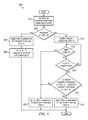
- FIG. 5 illustrates an example method 500 for dynamically configuring a SAS target device (e.g., target device 104 ).
- Method 500 may start at step 502 , where a target device, may receive an initialization request from an initiator.
- the initialization request may include an initiator identifier.
- the target device may be similar to target 104 depicted in FIG. 1 and may include two ports (ports A and B), similar to ports 110 a and 110 b .
- the present example is described with respect to a target device having only two ports, the disclosure should not be limited to such.
- the target device may have more than two ports, such as target 104 depicted with respect to FIG. 4 .
- the target device may determine whether the initiator identifier was received at port A or port B. If the initiator identifier was received at port A, the target device may proceed to step 506 . If the initiator identifier was received at port B, the target device may proceed to step 510 . In some instances, the target device may receive an initiator identifier at port A and shortly thereafter receive an initiator identifier at port B or vice versa. Accordingly, although some the following steps may be described in a sequential order, it is understood that the target device may perform the steps of method 500 associated with port A while also simultaneously performing some steps of method 500 associated with port B.
- the target device may send a port A identifier to the initiator through port A to configure and identify port A.
- the target device may set a bit or flag to indicate that port A has been configured, and method 500 may end.
- the target device may start a delay timer for port B.
- the target device may determine whether the timer has expired. If the timer has not expired, method 500 may proceed to step 514 , otherwise method 500 may proceed to step 520 .
- the target device may check the bit or flag that indicates whether port A has been configured to determine if port A has been configured. If port A has not been configured, the target device may return to step 512 to determine whether the delay timer has expired. If port A has been configured, the target device may proceed to step 516 .
- the target device may determine whether the initiator identifier received at port A is equal to the initiator identifier received at port B. If the initiator identifiers are equal, the target device may determine that ports A and B are coupled to the same initiator and may proceed to step 518 . If the identifiers are not equal, the target device may determine that ports A and B are not coupled to the same initiator and may proceed to step 520 .
- the target device may send the port A identifier through port B to the initiator coupled to both ports A and B. Accordingly, due to the initiator having also received the port A identifier through port A, as described in step 508 , the initiator may logically “see” ports A and B as one single port, such that port A and port B operate in wide mode. Following step 518 , the method may end.
- the target device may send a port B identifier through port B to the initiator that sent the initiator identifier to port B.
- port B may be configured in narrow mode and may operate as a single port independent from port A.
- the target device may also send a port B identifier through port B to the initiator that sent the initiator identifier to port B.
- port B may still be configured without having to indefinitely wait for port A to be configured, which may never happen. Following step 520 , method 500 may end.
- a target device may have more than two ports.
- the timer may be omitted.
Abstract
Description
Claims (20)
Priority Applications (1)
| Application Number | Priority Date | Filing Date | Title |
|---|---|---|---|
| US13/668,531 US8539116B2 (en) | 2010-09-24 | 2012-11-05 | System and method for dynamically configuring a target device |
Applications Claiming Priority (2)
| Application Number | Priority Date | Filing Date | Title |
|---|---|---|---|
| US12/890,062 US8312177B2 (en) | 2010-09-24 | 2010-09-24 | System and method for dynamically configuring a target device |
| US13/668,531 US8539116B2 (en) | 2010-09-24 | 2012-11-05 | System and method for dynamically configuring a target device |
Related Parent Applications (1)
| Application Number | Title | Priority Date | Filing Date |
|---|---|---|---|
| US12/890,062 Continuation US8312177B2 (en) | 2010-09-24 | 2010-09-24 | System and method for dynamically configuring a target device |
Publications (2)
| Publication Number | Publication Date |
|---|---|
| US20130060968A1 US20130060968A1 (en) | 2013-03-07 |
| US8539116B2 true US8539116B2 (en) | 2013-09-17 |
Family
ID=45871808
Family Applications (2)
| Application Number | Title | Priority Date | Filing Date |
|---|---|---|---|
| US12/890,062 Active 2030-12-30 US8312177B2 (en) | 2010-09-24 | 2010-09-24 | System and method for dynamically configuring a target device |
| US13/668,531 Active US8539116B2 (en) | 2010-09-24 | 2012-11-05 | System and method for dynamically configuring a target device |
Family Applications Before (1)
| Application Number | Title | Priority Date | Filing Date |
|---|---|---|---|
| US12/890,062 Active 2030-12-30 US8312177B2 (en) | 2010-09-24 | 2010-09-24 | System and method for dynamically configuring a target device |
Country Status (1)
| Country | Link |
|---|---|
| US (2) | US8312177B2 (en) |
Cited By (2)
| Publication number | Priority date | Publication date | Assignee | Title |
|---|---|---|---|---|
| US9501441B2 (en) | 2013-12-16 | 2016-11-22 | Dell Products, Lp | Mechanism to boot multiple hosts from a shared PCIe device |
| US11516256B2 (en) | 2020-05-20 | 2022-11-29 | Dell Products L.P. | Certificate authorization policy for security protocol and data model capable devices |
Families Citing this family (3)
| Publication number | Priority date | Publication date | Assignee | Title |
|---|---|---|---|---|
| JP5528243B2 (en) * | 2010-07-23 | 2014-06-25 | インターナショナル・ビジネス・マシーンズ・コーポレーション | System and method for controlling multipath |
| US10565041B2 (en) | 2017-05-19 | 2020-02-18 | Western Digital Technologies, Inc. | Managing phys of a data storage target device |
| US10735340B2 (en) * | 2018-04-18 | 2020-08-04 | Avago Technologies International Sales Pte. Limited | System and method for maximizing port bandwidth with multi-channel data paths |
Citations (7)
| Publication number | Priority date | Publication date | Assignee | Title |
|---|---|---|---|---|
| US5235689A (en) | 1990-06-11 | 1993-08-10 | Storage Technology Corporation | Interface circuit for dual port disk drive systems |
| US7058749B2 (en) | 2003-11-13 | 2006-06-06 | Dell Products L.P. | System and method for communications in serial attached SCSI storage network |
| US7290066B2 (en) | 2004-03-18 | 2007-10-30 | Lsi Corporation | Methods and structure for improved transfer rate performance in a SAS wide port environment |
| US7624206B2 (en) | 2005-09-29 | 2009-11-24 | Emc Corporation | RAID data storage system with SAS expansion |
| US7676613B2 (en) | 2004-08-03 | 2010-03-09 | Lsi Corporation | Methods and structure for assuring correct data order in SATA transmissions over a SAS wide port |
| US7769831B2 (en) | 2005-03-22 | 2010-08-03 | Lsi Corporation | System and method for SAS PHY dynamic configuration |
| US20100250785A1 (en) | 2009-03-24 | 2010-09-30 | George Shin | Npiv at storage devices |
-
2010
- 2010-09-24 US US12/890,062 patent/US8312177B2/en active Active
-
2012
- 2012-11-05 US US13/668,531 patent/US8539116B2/en active Active
Patent Citations (7)
| Publication number | Priority date | Publication date | Assignee | Title |
|---|---|---|---|---|
| US5235689A (en) | 1990-06-11 | 1993-08-10 | Storage Technology Corporation | Interface circuit for dual port disk drive systems |
| US7058749B2 (en) | 2003-11-13 | 2006-06-06 | Dell Products L.P. | System and method for communications in serial attached SCSI storage network |
| US7290066B2 (en) | 2004-03-18 | 2007-10-30 | Lsi Corporation | Methods and structure for improved transfer rate performance in a SAS wide port environment |
| US7676613B2 (en) | 2004-08-03 | 2010-03-09 | Lsi Corporation | Methods and structure for assuring correct data order in SATA transmissions over a SAS wide port |
| US7769831B2 (en) | 2005-03-22 | 2010-08-03 | Lsi Corporation | System and method for SAS PHY dynamic configuration |
| US7624206B2 (en) | 2005-09-29 | 2009-11-24 | Emc Corporation | RAID data storage system with SAS expansion |
| US20100250785A1 (en) | 2009-03-24 | 2010-09-30 | George Shin | Npiv at storage devices |
Cited By (3)
| Publication number | Priority date | Publication date | Assignee | Title |
|---|---|---|---|---|
| US9501441B2 (en) | 2013-12-16 | 2016-11-22 | Dell Products, Lp | Mechanism to boot multiple hosts from a shared PCIe device |
| US10146718B2 (en) | 2013-12-16 | 2018-12-04 | Dell Products, Lp | Mechanism to boot multiple hosts from a shared PCIe device |
| US11516256B2 (en) | 2020-05-20 | 2022-11-29 | Dell Products L.P. | Certificate authorization policy for security protocol and data model capable devices |
Also Published As
| Publication number | Publication date |
|---|---|
| US20130060968A1 (en) | 2013-03-07 |
| US20120079136A1 (en) | 2012-03-29 |
| US8312177B2 (en) | 2012-11-13 |
Similar Documents
| Publication | Publication Date | Title |
|---|---|---|
| US8539116B2 (en) | System and method for dynamically configuring a target device | |
| US8732520B2 (en) | Clustered array controller for global redundancy in a SAN | |
| US8782342B2 (en) | Systems and methods for automatically generating a mirrored storage configuration for a storage array | |
| US10628364B2 (en) | Dual port storage device performing peer-to-peer communication with external device without intervention of host | |
| US7958302B2 (en) | System and method for communicating data in a storage network | |
| US8938564B2 (en) | Processing input/output requests using proxy and owner storage systems | |
| US7743243B2 (en) | System and method to enable teamed network environments during network based initialization sequences | |
| US20090217067A1 (en) | Systems and Methods for Reducing Power Consumption in a Redundant Storage Array | |
| US7334042B2 (en) | Systems and methods for initiator mode connection management in SAS connections | |
| US10409737B2 (en) | Apparatus, system, and method for positionally aware device management bus address assignment | |
| US8296487B1 (en) | SATA pass through port | |
| US10855538B2 (en) | Single management connection automatic device stack configuration system | |
| US20140047134A1 (en) | Methods and structure for hardware management of serial advanced technology attachment (sata) dma non-zero offsets in a serial attached scsi (sas) expander | |
| US20040139196A1 (en) | System and method for releasing device reservations | |
| US9396140B1 (en) | Method and apparatus for transferring frames with different world wide name addresses and connection rates between initiators of a host device and a port | |
| US7434014B2 (en) | System and method for the self-mirroring storage drives | |
| US10911547B2 (en) | Systems and methods for SMB monitor dialect | |
| US20160350239A1 (en) | Method for resolving a cable mismatch in a target device | |
| US20170123657A1 (en) | Systems and methods for back up in scale-out storage area network | |
| US9286253B2 (en) | System and method for presenting devices through an SAS initiator-connected device | |
| US11231881B2 (en) | Raid data storage device multi-step command coordination system | |
| US20210294758A1 (en) | Systems and methods for queuing device management configuration requests | |
| US20160203078A1 (en) | Systems and methods for physical storage resource migration discovery | |
| US10146625B2 (en) | Systems and methods for intelligent data manager for offloading of bulk data transfers | |
| US11645216B2 (en) | Systems and methods for single-wire in-band pulse-addressable multiplexer |
Legal Events
| Date | Code | Title | Description |
|---|---|---|---|
| AS | Assignment |
Owner name: DELL PRODUCTS L.P., TEXAS Free format text: ASSIGNMENT OF ASSIGNORS INTEREST;ASSIGNORS:KOTZUR, GARY B.;NELOGAL, CHANDRASHEKAR;SIEBER, JOHN R.;AND OTHERS;SIGNING DATES FROM 20100909 TO 20100910;REEL/FRAME:029239/0715 |
|
| FEPP | Fee payment procedure |
Free format text: PAYOR NUMBER ASSIGNED (ORIGINAL EVENT CODE: ASPN); ENTITY STATUS OF PATENT OWNER: LARGE ENTITY |
|
| STCF | Information on status: patent grant |
Free format text: PATENTED CASE |
|
| AS | Assignment |
Owner name: BANK OF AMERICA, N.A., AS COLLATERAL AGENT, NORTH CAROLINA Free format text: PATENT SECURITY AGREEMENT (TERM LOAN);ASSIGNORS:DELL INC.;APPASSURE SOFTWARE, INC.;ASAP SOFTWARE EXPRESS, INC.;AND OTHERS;REEL/FRAME:031899/0261 Effective date: 20131029 Owner name: BANK OF AMERICA, N.A., AS ADMINISTRATIVE AGENT, TEXAS Free format text: PATENT SECURITY AGREEMENT (ABL);ASSIGNORS:DELL INC.;APPASSURE SOFTWARE, INC.;ASAP SOFTWARE EXPRESS, INC.;AND OTHERS;REEL/FRAME:031898/0001 Effective date: 20131029 Owner name: BANK OF NEW YORK MELLON TRUST COMPANY, N.A., AS FIRST LIEN COLLATERAL AGENT, TEXAS Free format text: PATENT SECURITY AGREEMENT (NOTES);ASSIGNORS:APPASSURE SOFTWARE, INC.;ASAP SOFTWARE EXPRESS, INC.;BOOMI, INC.;AND OTHERS;REEL/FRAME:031897/0348 Effective date: 20131029 Owner name: BANK OF AMERICA, N.A., AS COLLATERAL AGENT, NORTH Free format text: PATENT SECURITY AGREEMENT (TERM LOAN);ASSIGNORS:DELL INC.;APPASSURE SOFTWARE, INC.;ASAP SOFTWARE EXPRESS, INC.;AND OTHERS;REEL/FRAME:031899/0261 Effective date: 20131029 Owner name: BANK OF NEW YORK MELLON TRUST COMPANY, N.A., AS FI Free format text: PATENT SECURITY AGREEMENT (NOTES);ASSIGNORS:APPASSURE SOFTWARE, INC.;ASAP SOFTWARE EXPRESS, INC.;BOOMI, INC.;AND OTHERS;REEL/FRAME:031897/0348 Effective date: 20131029 Owner name: BANK OF AMERICA, N.A., AS ADMINISTRATIVE AGENT, TE Free format text: PATENT SECURITY AGREEMENT (ABL);ASSIGNORS:DELL INC.;APPASSURE SOFTWARE, INC.;ASAP SOFTWARE EXPRESS, INC.;AND OTHERS;REEL/FRAME:031898/0001 Effective date: 20131029 |
|
| AS | Assignment |
Owner name: CREDANT TECHNOLOGIES, INC., TEXAS Free format text: RELEASE BY SECURED PARTY;ASSIGNOR:BANK OF AMERICA, N.A., AS ADMINISTRATIVE AGENT;REEL/FRAME:040065/0216 Effective date: 20160907 Owner name: DELL USA L.P., TEXAS Free format text: RELEASE BY SECURED PARTY;ASSIGNOR:BANK OF AMERICA, N.A., AS ADMINISTRATIVE AGENT;REEL/FRAME:040065/0216 Effective date: 20160907 Owner name: ASAP SOFTWARE EXPRESS, INC., ILLINOIS Free format text: RELEASE BY SECURED PARTY;ASSIGNOR:BANK OF AMERICA, N.A., AS ADMINISTRATIVE AGENT;REEL/FRAME:040065/0216 Effective date: 20160907 Owner name: DELL SOFTWARE INC., CALIFORNIA Free format text: RELEASE BY SECURED PARTY;ASSIGNOR:BANK OF AMERICA, N.A., AS ADMINISTRATIVE AGENT;REEL/FRAME:040065/0216 Effective date: 20160907 Owner name: DELL MARKETING L.P., TEXAS Free format text: RELEASE BY SECURED PARTY;ASSIGNOR:BANK OF AMERICA, N.A., AS ADMINISTRATIVE AGENT;REEL/FRAME:040065/0216 Effective date: 20160907 Owner name: DELL PRODUCTS L.P., TEXAS Free format text: RELEASE BY SECURED PARTY;ASSIGNOR:BANK OF AMERICA, N.A., AS ADMINISTRATIVE AGENT;REEL/FRAME:040065/0216 Effective date: 20160907 Owner name: FORCE10 NETWORKS, INC., CALIFORNIA Free format text: RELEASE BY SECURED PARTY;ASSIGNOR:BANK OF AMERICA, N.A., AS ADMINISTRATIVE AGENT;REEL/FRAME:040065/0216 Effective date: 20160907 Owner name: APPASSURE SOFTWARE, INC., VIRGINIA Free format text: RELEASE BY SECURED PARTY;ASSIGNOR:BANK OF AMERICA, N.A., AS ADMINISTRATIVE AGENT;REEL/FRAME:040065/0216 Effective date: 20160907 Owner name: DELL INC., TEXAS Free format text: RELEASE BY SECURED PARTY;ASSIGNOR:BANK OF AMERICA, N.A., AS ADMINISTRATIVE AGENT;REEL/FRAME:040065/0216 Effective date: 20160907 Owner name: SECUREWORKS, INC., GEORGIA Free format text: RELEASE BY SECURED PARTY;ASSIGNOR:BANK OF AMERICA, N.A., AS ADMINISTRATIVE AGENT;REEL/FRAME:040065/0216 Effective date: 20160907 Owner name: WYSE TECHNOLOGY L.L.C., CALIFORNIA Free format text: RELEASE BY SECURED PARTY;ASSIGNOR:BANK OF AMERICA, N.A., AS ADMINISTRATIVE AGENT;REEL/FRAME:040065/0216 Effective date: 20160907 Owner name: COMPELLANT TECHNOLOGIES, INC., MINNESOTA Free format text: RELEASE BY SECURED PARTY;ASSIGNOR:BANK OF AMERICA, N.A., AS ADMINISTRATIVE AGENT;REEL/FRAME:040065/0216 Effective date: 20160907 Owner name: PEROT SYSTEMS CORPORATION, TEXAS Free format text: RELEASE BY SECURED PARTY;ASSIGNOR:BANK OF AMERICA, N.A., AS ADMINISTRATIVE AGENT;REEL/FRAME:040065/0216 Effective date: 20160907 |
|
| AS | Assignment |
Owner name: WYSE TECHNOLOGY L.L.C., CALIFORNIA Free format text: RELEASE BY SECURED PARTY;ASSIGNOR:BANK OF AMERICA, N.A., AS COLLATERAL AGENT;REEL/FRAME:040040/0001 Effective date: 20160907 Owner name: DELL INC., TEXAS Free format text: RELEASE BY SECURED PARTY;ASSIGNOR:BANK OF AMERICA, N.A., AS COLLATERAL AGENT;REEL/FRAME:040040/0001 Effective date: 20160907 Owner name: COMPELLENT TECHNOLOGIES, INC., MINNESOTA Free format text: RELEASE BY SECURED PARTY;ASSIGNOR:BANK OF AMERICA, N.A., AS COLLATERAL AGENT;REEL/FRAME:040040/0001 Effective date: 20160907 Owner name: PEROT SYSTEMS CORPORATION, TEXAS Free format text: RELEASE BY SECURED PARTY;ASSIGNOR:BANK OF AMERICA, N.A., AS COLLATERAL AGENT;REEL/FRAME:040040/0001 Effective date: 20160907 Owner name: DELL MARKETING L.P., TEXAS Free format text: RELEASE BY SECURED PARTY;ASSIGNOR:BANK OF AMERICA, N.A., AS COLLATERAL AGENT;REEL/FRAME:040040/0001 Effective date: 20160907 Owner name: ASAP SOFTWARE EXPRESS, INC., ILLINOIS Free format text: RELEASE BY SECURED PARTY;ASSIGNOR:BANK OF AMERICA, N.A., AS COLLATERAL AGENT;REEL/FRAME:040040/0001 Effective date: 20160907 Owner name: DELL PRODUCTS L.P., TEXAS Free format text: RELEASE BY SECURED PARTY;ASSIGNOR:BANK OF AMERICA, N.A., AS COLLATERAL AGENT;REEL/FRAME:040040/0001 Effective date: 20160907 Owner name: DELL SOFTWARE INC., CALIFORNIA Free format text: RELEASE BY SECURED PARTY;ASSIGNOR:BANK OF AMERICA, N.A., AS COLLATERAL AGENT;REEL/FRAME:040040/0001 Effective date: 20160907 Owner name: APPASSURE SOFTWARE, INC., VIRGINIA Free format text: RELEASE BY SECURED PARTY;ASSIGNOR:BANK OF AMERICA, N.A., AS COLLATERAL AGENT;REEL/FRAME:040040/0001 Effective date: 20160907 Owner name: DELL USA L.P., TEXAS Free format text: RELEASE BY SECURED PARTY;ASSIGNOR:BANK OF AMERICA, N.A., AS COLLATERAL AGENT;REEL/FRAME:040040/0001 Effective date: 20160907 Owner name: CREDANT TECHNOLOGIES, INC., TEXAS Free format text: RELEASE BY SECURED PARTY;ASSIGNOR:BANK OF AMERICA, N.A., AS COLLATERAL AGENT;REEL/FRAME:040040/0001 Effective date: 20160907 Owner name: FORCE10 NETWORKS, INC., CALIFORNIA Free format text: RELEASE BY SECURED PARTY;ASSIGNOR:BANK OF AMERICA, N.A., AS COLLATERAL AGENT;REEL/FRAME:040040/0001 Effective date: 20160907 Owner name: SECUREWORKS, INC., GEORGIA Free format text: RELEASE BY SECURED PARTY;ASSIGNOR:BANK OF AMERICA, N.A., AS COLLATERAL AGENT;REEL/FRAME:040040/0001 Effective date: 20160907 Owner name: DELL MARKETING L.P., TEXAS Free format text: RELEASE BY SECURED PARTY;ASSIGNOR:BANK OF NEW YORK MELLON TRUST COMPANY, N.A., AS COLLATERAL AGENT;REEL/FRAME:040065/0618 Effective date: 20160907 Owner name: DELL PRODUCTS L.P., TEXAS Free format text: RELEASE BY SECURED PARTY;ASSIGNOR:BANK OF NEW YORK MELLON TRUST COMPANY, N.A., AS COLLATERAL AGENT;REEL/FRAME:040065/0618 Effective date: 20160907 Owner name: SECUREWORKS, INC., GEORGIA Free format text: RELEASE BY SECURED PARTY;ASSIGNOR:BANK OF NEW YORK MELLON TRUST COMPANY, N.A., AS COLLATERAL AGENT;REEL/FRAME:040065/0618 Effective date: 20160907 Owner name: WYSE TECHNOLOGY L.L.C., CALIFORNIA Free format text: RELEASE BY SECURED PARTY;ASSIGNOR:BANK OF NEW YORK MELLON TRUST COMPANY, N.A., AS COLLATERAL AGENT;REEL/FRAME:040065/0618 Effective date: 20160907 Owner name: FORCE10 NETWORKS, INC., CALIFORNIA Free format text: RELEASE BY SECURED PARTY;ASSIGNOR:BANK OF NEW YORK MELLON TRUST COMPANY, N.A., AS COLLATERAL AGENT;REEL/FRAME:040065/0618 Effective date: 20160907 Owner name: ASAP SOFTWARE EXPRESS, INC., ILLINOIS Free format text: RELEASE BY SECURED PARTY;ASSIGNOR:BANK OF NEW YORK MELLON TRUST COMPANY, N.A., AS COLLATERAL AGENT;REEL/FRAME:040065/0618 Effective date: 20160907 Owner name: PEROT SYSTEMS CORPORATION, TEXAS Free format text: RELEASE BY SECURED PARTY;ASSIGNOR:BANK OF NEW YORK MELLON TRUST COMPANY, N.A., AS COLLATERAL AGENT;REEL/FRAME:040065/0618 Effective date: 20160907 Owner name: COMPELLENT TECHNOLOGIES, INC., MINNESOTA Free format text: RELEASE BY SECURED PARTY;ASSIGNOR:BANK OF NEW YORK MELLON TRUST COMPANY, N.A., AS COLLATERAL AGENT;REEL/FRAME:040065/0618 Effective date: 20160907 Owner name: APPASSURE SOFTWARE, INC., VIRGINIA Free format text: RELEASE BY SECURED PARTY;ASSIGNOR:BANK OF NEW YORK MELLON TRUST COMPANY, N.A., AS COLLATERAL AGENT;REEL/FRAME:040065/0618 Effective date: 20160907 Owner name: DELL INC., TEXAS Free format text: RELEASE BY SECURED PARTY;ASSIGNOR:BANK OF NEW YORK MELLON TRUST COMPANY, N.A., AS COLLATERAL AGENT;REEL/FRAME:040065/0618 Effective date: 20160907 Owner name: DELL SOFTWARE INC., CALIFORNIA Free format text: RELEASE BY SECURED PARTY;ASSIGNOR:BANK OF NEW YORK MELLON TRUST COMPANY, N.A., AS COLLATERAL AGENT;REEL/FRAME:040065/0618 Effective date: 20160907 Owner name: DELL USA L.P., TEXAS Free format text: RELEASE BY SECURED PARTY;ASSIGNOR:BANK OF NEW YORK MELLON TRUST COMPANY, N.A., AS COLLATERAL AGENT;REEL/FRAME:040065/0618 Effective date: 20160907 Owner name: CREDANT TECHNOLOGIES, INC., TEXAS Free format text: RELEASE BY SECURED PARTY;ASSIGNOR:BANK OF NEW YORK MELLON TRUST COMPANY, N.A., AS COLLATERAL AGENT;REEL/FRAME:040065/0618 Effective date: 20160907 |
|
| AS | Assignment |
Owner name: CREDIT SUISSE AG, CAYMAN ISLANDS BRANCH, AS COLLATERAL AGENT, NORTH CAROLINA Free format text: SECURITY AGREEMENT;ASSIGNORS:ASAP SOFTWARE EXPRESS, INC.;AVENTAIL LLC;CREDANT TECHNOLOGIES, INC.;AND OTHERS;REEL/FRAME:040134/0001 Effective date: 20160907 Owner name: THE BANK OF NEW YORK MELLON TRUST COMPANY, N.A., AS NOTES COLLATERAL AGENT, TEXAS Free format text: SECURITY AGREEMENT;ASSIGNORS:ASAP SOFTWARE EXPRESS, INC.;AVENTAIL LLC;CREDANT TECHNOLOGIES, INC.;AND OTHERS;REEL/FRAME:040136/0001 Effective date: 20160907 Owner name: CREDIT SUISSE AG, CAYMAN ISLANDS BRANCH, AS COLLAT Free format text: SECURITY AGREEMENT;ASSIGNORS:ASAP SOFTWARE EXPRESS, INC.;AVENTAIL LLC;CREDANT TECHNOLOGIES, INC.;AND OTHERS;REEL/FRAME:040134/0001 Effective date: 20160907 Owner name: THE BANK OF NEW YORK MELLON TRUST COMPANY, N.A., A Free format text: SECURITY AGREEMENT;ASSIGNORS:ASAP SOFTWARE EXPRESS, INC.;AVENTAIL LLC;CREDANT TECHNOLOGIES, INC.;AND OTHERS;REEL/FRAME:040136/0001 Effective date: 20160907 |
|
| FPAY | Fee payment |
Year of fee payment: 4 |
|
| AS | Assignment |
Owner name: THE BANK OF NEW YORK MELLON TRUST COMPANY, N.A., T Free format text: SECURITY AGREEMENT;ASSIGNORS:CREDANT TECHNOLOGIES, INC.;DELL INTERNATIONAL L.L.C.;DELL MARKETING L.P.;AND OTHERS;REEL/FRAME:049452/0223 Effective date: 20190320 Owner name: THE BANK OF NEW YORK MELLON TRUST COMPANY, N.A., TEXAS Free format text: SECURITY AGREEMENT;ASSIGNORS:CREDANT TECHNOLOGIES, INC.;DELL INTERNATIONAL L.L.C.;DELL MARKETING L.P.;AND OTHERS;REEL/FRAME:049452/0223 Effective date: 20190320 |
|
| AS | Assignment |
Owner name: THE BANK OF NEW YORK MELLON TRUST COMPANY, N.A., TEXAS Free format text: SECURITY AGREEMENT;ASSIGNORS:CREDANT TECHNOLOGIES INC.;DELL INTERNATIONAL L.L.C.;DELL MARKETING L.P.;AND OTHERS;REEL/FRAME:053546/0001 Effective date: 20200409 |
|
| MAFP | Maintenance fee payment |
Free format text: PAYMENT OF MAINTENANCE FEE, 8TH YEAR, LARGE ENTITY (ORIGINAL EVENT CODE: M1552); ENTITY STATUS OF PATENT OWNER: LARGE ENTITY Year of fee payment: 8 |
|
| AS | Assignment |
Owner name: WYSE TECHNOLOGY L.L.C., CALIFORNIA Free format text: RELEASE BY SECURED PARTY;ASSIGNOR:CREDIT SUISSE AG, CAYMAN ISLANDS BRANCH;REEL/FRAME:058216/0001 Effective date: 20211101 Owner name: SCALEIO LLC, MASSACHUSETTS Free format text: RELEASE BY SECURED PARTY;ASSIGNOR:CREDIT SUISSE AG, CAYMAN ISLANDS BRANCH;REEL/FRAME:058216/0001 Effective date: 20211101 Owner name: MOZY, INC., WASHINGTON Free format text: RELEASE BY SECURED PARTY;ASSIGNOR:CREDIT SUISSE AG, CAYMAN ISLANDS BRANCH;REEL/FRAME:058216/0001 Effective date: 20211101 Owner name: MAGINATICS LLC, CALIFORNIA Free format text: RELEASE BY SECURED PARTY;ASSIGNOR:CREDIT SUISSE AG, CAYMAN ISLANDS BRANCH;REEL/FRAME:058216/0001 Effective date: 20211101 Owner name: FORCE10 NETWORKS, INC., CALIFORNIA Free format text: RELEASE BY SECURED PARTY;ASSIGNOR:CREDIT SUISSE AG, CAYMAN ISLANDS BRANCH;REEL/FRAME:058216/0001 Effective date: 20211101 Owner name: EMC IP HOLDING COMPANY LLC, TEXAS Free format text: RELEASE BY SECURED PARTY;ASSIGNOR:CREDIT SUISSE AG, CAYMAN ISLANDS BRANCH;REEL/FRAME:058216/0001 Effective date: 20211101 Owner name: EMC CORPORATION, MASSACHUSETTS Free format text: RELEASE BY SECURED PARTY;ASSIGNOR:CREDIT SUISSE AG, CAYMAN ISLANDS BRANCH;REEL/FRAME:058216/0001 Effective date: 20211101 Owner name: DELL SYSTEMS CORPORATION, TEXAS Free format text: RELEASE BY SECURED PARTY;ASSIGNOR:CREDIT SUISSE AG, CAYMAN ISLANDS BRANCH;REEL/FRAME:058216/0001 Effective date: 20211101 Owner name: DELL SOFTWARE INC., CALIFORNIA Free format text: RELEASE BY SECURED PARTY;ASSIGNOR:CREDIT SUISSE AG, CAYMAN ISLANDS BRANCH;REEL/FRAME:058216/0001 Effective date: 20211101 Owner name: DELL PRODUCTS L.P., TEXAS Free format text: RELEASE BY SECURED PARTY;ASSIGNOR:CREDIT SUISSE AG, CAYMAN ISLANDS BRANCH;REEL/FRAME:058216/0001 Effective date: 20211101 Owner name: DELL MARKETING L.P., TEXAS Free format text: RELEASE BY SECURED PARTY;ASSIGNOR:CREDIT SUISSE AG, CAYMAN ISLANDS BRANCH;REEL/FRAME:058216/0001 Effective date: 20211101 Owner name: DELL INTERNATIONAL, L.L.C., TEXAS Free format text: RELEASE BY SECURED PARTY;ASSIGNOR:CREDIT SUISSE AG, CAYMAN ISLANDS BRANCH;REEL/FRAME:058216/0001 Effective date: 20211101 Owner name: DELL USA L.P., TEXAS Free format text: RELEASE BY SECURED PARTY;ASSIGNOR:CREDIT SUISSE AG, CAYMAN ISLANDS BRANCH;REEL/FRAME:058216/0001 Effective date: 20211101 Owner name: CREDANT TECHNOLOGIES, INC., TEXAS Free format text: RELEASE BY SECURED PARTY;ASSIGNOR:CREDIT SUISSE AG, CAYMAN ISLANDS BRANCH;REEL/FRAME:058216/0001 Effective date: 20211101 Owner name: AVENTAIL LLC, CALIFORNIA Free format text: RELEASE BY SECURED PARTY;ASSIGNOR:CREDIT SUISSE AG, CAYMAN ISLANDS BRANCH;REEL/FRAME:058216/0001 Effective date: 20211101 Owner name: ASAP SOFTWARE EXPRESS, INC., ILLINOIS Free format text: RELEASE BY SECURED PARTY;ASSIGNOR:CREDIT SUISSE AG, CAYMAN ISLANDS BRANCH;REEL/FRAME:058216/0001 Effective date: 20211101 |
|
| AS | Assignment |
Owner name: SCALEIO LLC, MASSACHUSETTS Free format text: RELEASE OF SECURITY INTEREST IN PATENTS PREVIOUSLY RECORDED AT REEL/FRAME (040136/0001);ASSIGNOR:THE BANK OF NEW YORK MELLON TRUST COMPANY, N.A., AS NOTES COLLATERAL AGENT;REEL/FRAME:061324/0001 Effective date: 20220329 Owner name: EMC IP HOLDING COMPANY LLC (ON BEHALF OF ITSELF AND AS SUCCESSOR-IN-INTEREST TO MOZY, INC.), TEXAS Free format text: RELEASE OF SECURITY INTEREST IN PATENTS PREVIOUSLY RECORDED AT REEL/FRAME (040136/0001);ASSIGNOR:THE BANK OF NEW YORK MELLON TRUST COMPANY, N.A., AS NOTES COLLATERAL AGENT;REEL/FRAME:061324/0001 Effective date: 20220329 Owner name: EMC CORPORATION (ON BEHALF OF ITSELF AND AS SUCCESSOR-IN-INTEREST TO MAGINATICS LLC), MASSACHUSETTS Free format text: RELEASE OF SECURITY INTEREST IN PATENTS PREVIOUSLY RECORDED AT REEL/FRAME (040136/0001);ASSIGNOR:THE BANK OF NEW YORK MELLON TRUST COMPANY, N.A., AS NOTES COLLATERAL AGENT;REEL/FRAME:061324/0001 Effective date: 20220329 Owner name: DELL MARKETING CORPORATION (SUCCESSOR-IN-INTEREST TO FORCE10 NETWORKS, INC. AND WYSE TECHNOLOGY L.L.C.), TEXAS Free format text: RELEASE OF SECURITY INTEREST IN PATENTS PREVIOUSLY RECORDED AT REEL/FRAME (040136/0001);ASSIGNOR:THE BANK OF NEW YORK MELLON TRUST COMPANY, N.A., AS NOTES COLLATERAL AGENT;REEL/FRAME:061324/0001 Effective date: 20220329 Owner name: DELL PRODUCTS L.P., TEXAS Free format text: RELEASE OF SECURITY INTEREST IN PATENTS PREVIOUSLY RECORDED AT REEL/FRAME (040136/0001);ASSIGNOR:THE BANK OF NEW YORK MELLON TRUST COMPANY, N.A., AS NOTES COLLATERAL AGENT;REEL/FRAME:061324/0001 Effective date: 20220329 Owner name: DELL INTERNATIONAL L.L.C., TEXAS Free format text: RELEASE OF SECURITY INTEREST IN PATENTS PREVIOUSLY RECORDED AT REEL/FRAME (040136/0001);ASSIGNOR:THE BANK OF NEW YORK MELLON TRUST COMPANY, N.A., AS NOTES COLLATERAL AGENT;REEL/FRAME:061324/0001 Effective date: 20220329 Owner name: DELL USA L.P., TEXAS Free format text: RELEASE OF SECURITY INTEREST IN PATENTS PREVIOUSLY RECORDED AT REEL/FRAME (040136/0001);ASSIGNOR:THE BANK OF NEW YORK MELLON TRUST COMPANY, N.A., AS NOTES COLLATERAL AGENT;REEL/FRAME:061324/0001 Effective date: 20220329 Owner name: DELL MARKETING L.P. (ON BEHALF OF ITSELF AND AS SUCCESSOR-IN-INTEREST TO CREDANT TECHNOLOGIES, INC.), TEXAS Free format text: RELEASE OF SECURITY INTEREST IN PATENTS PREVIOUSLY RECORDED AT REEL/FRAME (040136/0001);ASSIGNOR:THE BANK OF NEW YORK MELLON TRUST COMPANY, N.A., AS NOTES COLLATERAL AGENT;REEL/FRAME:061324/0001 Effective date: 20220329 Owner name: DELL MARKETING CORPORATION (SUCCESSOR-IN-INTEREST TO ASAP SOFTWARE EXPRESS, INC.), TEXAS Free format text: RELEASE OF SECURITY INTEREST IN PATENTS PREVIOUSLY RECORDED AT REEL/FRAME (040136/0001);ASSIGNOR:THE BANK OF NEW YORK MELLON TRUST COMPANY, N.A., AS NOTES COLLATERAL AGENT;REEL/FRAME:061324/0001 Effective date: 20220329 |
|
| AS | Assignment |
Owner name: SCALEIO LLC, MASSACHUSETTS Free format text: RELEASE OF SECURITY INTEREST IN PATENTS PREVIOUSLY RECORDED AT REEL/FRAME (045455/0001);ASSIGNOR:THE BANK OF NEW YORK MELLON TRUST COMPANY, N.A., AS NOTES COLLATERAL AGENT;REEL/FRAME:061753/0001 Effective date: 20220329 Owner name: EMC IP HOLDING COMPANY LLC (ON BEHALF OF ITSELF AND AS SUCCESSOR-IN-INTEREST TO MOZY, INC.), TEXAS Free format text: RELEASE OF SECURITY INTEREST IN PATENTS PREVIOUSLY RECORDED AT REEL/FRAME (045455/0001);ASSIGNOR:THE BANK OF NEW YORK MELLON TRUST COMPANY, N.A., AS NOTES COLLATERAL AGENT;REEL/FRAME:061753/0001 Effective date: 20220329 Owner name: EMC CORPORATION (ON BEHALF OF ITSELF AND AS SUCCESSOR-IN-INTEREST TO MAGINATICS LLC), MASSACHUSETTS Free format text: RELEASE OF SECURITY INTEREST IN PATENTS PREVIOUSLY RECORDED AT REEL/FRAME (045455/0001);ASSIGNOR:THE BANK OF NEW YORK MELLON TRUST COMPANY, N.A., AS NOTES COLLATERAL AGENT;REEL/FRAME:061753/0001 Effective date: 20220329 Owner name: DELL MARKETING CORPORATION (SUCCESSOR-IN-INTEREST TO FORCE10 NETWORKS, INC. AND WYSE TECHNOLOGY L.L.C.), TEXAS Free format text: RELEASE OF SECURITY INTEREST IN PATENTS PREVIOUSLY RECORDED AT REEL/FRAME (045455/0001);ASSIGNOR:THE BANK OF NEW YORK MELLON TRUST COMPANY, N.A., AS NOTES COLLATERAL AGENT;REEL/FRAME:061753/0001 Effective date: 20220329 Owner name: DELL PRODUCTS L.P., TEXAS Free format text: RELEASE OF SECURITY INTEREST IN PATENTS PREVIOUSLY RECORDED AT REEL/FRAME (045455/0001);ASSIGNOR:THE BANK OF NEW YORK MELLON TRUST COMPANY, N.A., AS NOTES COLLATERAL AGENT;REEL/FRAME:061753/0001 Effective date: 20220329 Owner name: DELL INTERNATIONAL L.L.C., TEXAS Free format text: RELEASE OF SECURITY INTEREST IN PATENTS PREVIOUSLY RECORDED AT REEL/FRAME (045455/0001);ASSIGNOR:THE BANK OF NEW YORK MELLON TRUST COMPANY, N.A., AS NOTES COLLATERAL AGENT;REEL/FRAME:061753/0001 Effective date: 20220329 Owner name: DELL USA L.P., TEXAS Free format text: RELEASE OF SECURITY INTEREST IN PATENTS PREVIOUSLY RECORDED AT REEL/FRAME (045455/0001);ASSIGNOR:THE BANK OF NEW YORK MELLON TRUST COMPANY, N.A., AS NOTES COLLATERAL AGENT;REEL/FRAME:061753/0001 Effective date: 20220329 Owner name: DELL MARKETING L.P. (ON BEHALF OF ITSELF AND AS SUCCESSOR-IN-INTEREST TO CREDANT TECHNOLOGIES, INC.), TEXAS Free format text: RELEASE OF SECURITY INTEREST IN PATENTS PREVIOUSLY RECORDED AT REEL/FRAME (045455/0001);ASSIGNOR:THE BANK OF NEW YORK MELLON TRUST COMPANY, N.A., AS NOTES COLLATERAL AGENT;REEL/FRAME:061753/0001 Effective date: 20220329 Owner name: DELL MARKETING CORPORATION (SUCCESSOR-IN-INTEREST TO ASAP SOFTWARE EXPRESS, INC.), TEXAS Free format text: RELEASE OF SECURITY INTEREST IN PATENTS PREVIOUSLY RECORDED AT REEL/FRAME (045455/0001);ASSIGNOR:THE BANK OF NEW YORK MELLON TRUST COMPANY, N.A., AS NOTES COLLATERAL AGENT;REEL/FRAME:061753/0001 Effective date: 20220329 |