US8534673B2 - Inter stage seal housing having a replaceable wear strip - Google Patents
Inter stage seal housing having a replaceable wear strip Download PDFInfo
- Publication number
- US8534673B2 US8534673B2 US12/860,359 US86035910A US8534673B2 US 8534673 B2 US8534673 B2 US 8534673B2 US 86035910 A US86035910 A US 86035910A US 8534673 B2 US8534673 B2 US 8534673B2
- Authority
- US
- United States
- Prior art keywords
- sealing surface
- seal housing
- strips
- circumferential
- seal
- Prior art date
- Legal status (The legal status is an assumption and is not a legal conclusion. Google has not performed a legal analysis and makes no representation as to the accuracy of the status listed.)
- Active, expires
Links
- 238000007789 sealing Methods 0.000 claims abstract description 105
- 230000014759 maintenance of location Effects 0.000 claims abstract description 25
- 238000011144 upstream manufacturing Methods 0.000 claims description 23
- 230000007246 mechanism Effects 0.000 claims description 7
- 238000000034 method Methods 0.000 claims 2
- 230000002093 peripheral effect Effects 0.000 abstract 1
- 238000009434 installation Methods 0.000 description 3
- 238000012423 maintenance Methods 0.000 description 3
- 230000004048 modification Effects 0.000 description 3
- 238000012986 modification Methods 0.000 description 3
- 230000008901 benefit Effects 0.000 description 2
- 238000003466 welding Methods 0.000 description 2
- 238000001816 cooling Methods 0.000 description 1
- 238000003754 machining Methods 0.000 description 1
- 230000002035 prolonged effect Effects 0.000 description 1
- 230000008439 repair process Effects 0.000 description 1
Images


Classifications
-
- F—MECHANICAL ENGINEERING; LIGHTING; HEATING; WEAPONS; BLASTING
- F01—MACHINES OR ENGINES IN GENERAL; ENGINE PLANTS IN GENERAL; STEAM ENGINES
- F01D—NON-POSITIVE DISPLACEMENT MACHINES OR ENGINES, e.g. STEAM TURBINES
- F01D9/00—Stators
-
- F—MECHANICAL ENGINEERING; LIGHTING; HEATING; WEAPONS; BLASTING
- F01—MACHINES OR ENGINES IN GENERAL; ENGINE PLANTS IN GENERAL; STEAM ENGINES
- F01D—NON-POSITIVE DISPLACEMENT MACHINES OR ENGINES, e.g. STEAM TURBINES
- F01D11/00—Preventing or minimising internal leakage of working-fluid, e.g. between stages
- F01D11/001—Preventing or minimising internal leakage of working-fluid, e.g. between stages for sealing space between stator blade and rotor
-
- F—MECHANICAL ENGINEERING; LIGHTING; HEATING; WEAPONS; BLASTING
- F01—MACHINES OR ENGINES IN GENERAL; ENGINE PLANTS IN GENERAL; STEAM ENGINES
- F01D—NON-POSITIVE DISPLACEMENT MACHINES OR ENGINES, e.g. STEAM TURBINES
- F01D11/00—Preventing or minimising internal leakage of working-fluid, e.g. between stages
- F01D11/08—Preventing or minimising internal leakage of working-fluid, e.g. between stages for sealing space between rotor blade tips and stator
- F01D11/12—Preventing or minimising internal leakage of working-fluid, e.g. between stages for sealing space between rotor blade tips and stator using a rubstrip, e.g. erodible. deformable or resiliently-biased part
-
- F—MECHANICAL ENGINEERING; LIGHTING; HEATING; WEAPONS; BLASTING
- F01—MACHINES OR ENGINES IN GENERAL; ENGINE PLANTS IN GENERAL; STEAM ENGINES
- F01D—NON-POSITIVE DISPLACEMENT MACHINES OR ENGINES, e.g. STEAM TURBINES
- F01D11/00—Preventing or minimising internal leakage of working-fluid, e.g. between stages
- F01D11/08—Preventing or minimising internal leakage of working-fluid, e.g. between stages for sealing space between rotor blade tips and stator
- F01D11/12—Preventing or minimising internal leakage of working-fluid, e.g. between stages for sealing space between rotor blade tips and stator using a rubstrip, e.g. erodible. deformable or resiliently-biased part
- F01D11/122—Preventing or minimising internal leakage of working-fluid, e.g. between stages for sealing space between rotor blade tips and stator using a rubstrip, e.g. erodible. deformable or resiliently-biased part with erodable or abradable material
-
- F—MECHANICAL ENGINEERING; LIGHTING; HEATING; WEAPONS; BLASTING
- F05—INDEXING SCHEMES RELATING TO ENGINES OR PUMPS IN VARIOUS SUBCLASSES OF CLASSES F01-F04
- F05D—INDEXING SCHEME FOR ASPECTS RELATING TO NON-POSITIVE-DISPLACEMENT MACHINES OR ENGINES, GAS-TURBINES OR JET-PROPULSION PLANTS
- F05D2230/00—Manufacture
- F05D2230/72—Maintenance
-
- F—MECHANICAL ENGINEERING; LIGHTING; HEATING; WEAPONS; BLASTING
- F05—INDEXING SCHEMES RELATING TO ENGINES OR PUMPS IN VARIOUS SUBCLASSES OF CLASSES F01-F04
- F05D—INDEXING SCHEME FOR ASPECTS RELATING TO NON-POSITIVE-DISPLACEMENT MACHINES OR ENGINES, GAS-TURBINES OR JET-PROPULSION PLANTS
- F05D2240/00—Components
- F05D2240/40—Use of a multiplicity of similar components
-
- F—MECHANICAL ENGINEERING; LIGHTING; HEATING; WEAPONS; BLASTING
- F05—INDEXING SCHEMES RELATING TO ENGINES OR PUMPS IN VARIOUS SUBCLASSES OF CLASSES F01-F04
- F05D—INDEXING SCHEME FOR ASPECTS RELATING TO NON-POSITIVE-DISPLACEMENT MACHINES OR ENGINES, GAS-TURBINES OR JET-PROPULSION PLANTS
- F05D2240/00—Components
- F05D2240/55—Seals
-
- F—MECHANICAL ENGINEERING; LIGHTING; HEATING; WEAPONS; BLASTING
- F05—INDEXING SCHEMES RELATING TO ENGINES OR PUMPS IN VARIOUS SUBCLASSES OF CLASSES F01-F04
- F05D—INDEXING SCHEME FOR ASPECTS RELATING TO NON-POSITIVE-DISPLACEMENT MACHINES OR ENGINES, GAS-TURBINES OR JET-PROPULSION PLANTS
- F05D2250/00—Geometry
- F05D2250/30—Arrangement of components
- F05D2250/37—Arrangement of components circumferential
Definitions
- This invention relates to using a replaceable wear strip in an inter stage seal housing for a turbine engine, and more particularly, but not by way of limitation, to using the replaceable wear strip to restore a downstream sealing surface of the inter stage seal housing for the turbine engine after prolonged engine usage.
- FIG. 1 shows an enlarged cross-sectional view of a conventional inter stage seal housing 10 , which includes a downstream contact sealing surface 13 .
- FIG. 2 shows an enlarged fragmentary cross-sectional view of the conventional inter stage seal housing 10 shown in FIG. 1 together with a stationary airfoil 14 .
- the downstream contact sealing surface 13 of the conventional inter stage seal assembly 10 prevents the flow 15 from passing between the inter stage seal housing 10 and a stationary airfoil 14 of the turbine.
- downstream contact sealing surface 13 of the inter stage seal housing 10 eventually causes the downstream contact sealing surface 13 of the inter stage seal housing 10 to wear with the amount of wear being proportional to the number of hours of engine operation. Excessive wear of the downstream contact sealing surface 13 can create a leak path, which can negatively affect the cooling efficiency of the associated rotor disc cavity, vane inner shrouds and overall engine efficiency and performance of the turbine engine.
- downstream contact sealing surface 13 of the inter stage seal housing 10 is examined for excess wear and possible leaks. If excess wear and/or any leaks are found, the downstream contact sealing surface 13 of inter stage seal housing 10 must be welded in order to restore the downstream contact sealing surface 13 to its original shape.
- this type of weld building repair tends to be very time consuming, which leads to increase service expenses, and the downstream contact sealing surface 13 becomes distorted as a result of the weld buildup, which imparts on the performance of the turbine engine.
- the seal assembly for a turbine engine comprising a seal housing having a circumferential groove located along an edge of the seal housing, the circumferential groove having a plurality of through holes, at least one replaceable segment strip, each having at least one threaded hole, an upstream sealing surface, a downstream sealing surface, a right circumferential sealing surface and a left circumferential sealing surface, and a plurality of fasteners for securing segment strips in the circumferential groove, the circumferential groove being configured to accept the geometry of the strip(s).
- the seal housing further comprises a downstream surface, wherein the downstream sealing surface of the secured segment strips forms a substantially planar surface with the downstream surface of the seal housing and serves as a replaceable contact surface strip for the seal housing, and an upstream surface, wherein the plurality of through holes extend from the upstream surface to the circumferential groove.
- the upstream sealing surface of the secured segment strip forms an upstream contact sealing surface with the seal housing
- the downstream sealing surface of the secured segment strip forms a downstream contact sealing surface with a stationary member of the turbine engine
- the right circumferential sealing surface of the secured segment strip forms a first circumferential contact sealing surface with another left circumferential sealing surface of an adjacently secured sealing segment
- the left circumferential sealing surface of the secured segment strip forms a second circumferential contact sealing surface with another right circumferential sealing surface of another adjacently secured sealing segment
- the first and second circumferential contact sealing surfaces are configured to prevent leakage between adjacently secured segment strips with the first and second circumferential contact sealing surface having a step portion.
- the plurality of fasteners comprises a first fastener for securing the segment strip to the circumferential groove by engaging a first threaded hole of the segment strip via a first through hole of circumferential groove, at least one additional fastener for securing the segment strip to the circumferential groove by engaging at least one additional threaded hole of the segment strip via at least one additional through hole of circumferential groove, wherein the second fastener has a reduced diameter portion relative to the first fastener, which creates a larger clearance between the second fastener and the second through hole than between the first fastener and the first through hole.
- the fasteners provide additional clamping force between the seal housing and the secured segment strip, and the larger clearance between the second fastener and the second through hole allows for thermal expansion of the seal housing during operation of the turbine engine, wherein the fasteners prevent unwanted relative movement and wear between the seal housing and the secured segment strip and fastener retention means is for minimizing disbanding of the fasteners during turbine engine operation.
- the seal housing includes an upper half seal housing; a lower half seal housing and a horizontal split formed between said upper and lower half seal housing, and the circumferential groove includes a radial retention mechanism for retaining the secured segment strips in a radial direction and an axial locating mechanism for positioning the secured segment strips in a axial direction.
- each segment strip is slid into the groove from the horizontal split of the upper and the lower seal housing and the threaded holes of each segment strip are aligned with corresponding through holes of the grooves where fasteners and fastener retention components are threaded and torque is applied.
- FIG. 1 is an enlarged cross-sectional view of a conventional inter stage seal housing
- FIG. 2 is an enlarged fragmentary cross-sectional view of the conventional inter stage seal housing and a stationary airfoil;
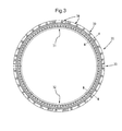
- FIG. 3 is an elevational view of an inter stage seal housing in accordance with a first exemplary embodiment of the present invention
- FIG. 4 is an enlarged cross-sectional view of the inter stage seal housing taken along line 4 - 4 of FIG. 3 without a replaceable wear strip installed in accordance with the first exemplary embodiment of the present invention
- FIG. 5 is an elevational view of a replaceable wear strip in accordance with the first exemplary embodiment of the invention.
- FIG. 6 is an enlarged cross-sectional view of an inter stage seal housing taken along line 6 - 6 of FIG. 3 , which shows a replaceable wear segment strip secured in the inter stage seal housing in accordance with the first exemplary embodiment of the invention;
- FIG. 7 is an enlarged fragmentary elevational plan view showing the configuration of circumferential sealing surfaces between two adjacent wear segment strips secured in the inter stage seal housing;
- FIGS. 8A-8C are elevational views of fastener equipment used to secure a replaceable wear segment strip to an inter stage seal housing in accordance with the first exemplary embodiment of the invention.
- FIG. 9 is an elevational view of an inter stage seal housing in accordance with a second exemplary embodiment of the present invention.
- FIG. 10 is an elevational view of a replaceable wear strip in accordance with the second exemplary embodiment of the invention.
- FIG. 11 is an enlarged cross-sectional view of the inter stage seal housing taken along line 11 - 11 of FIG. 9 without a replaceable wear strip installed in accordance with the second exemplary embodiment of the invention.
- FIG. 12 is an enlarged cross-sectional view of an inter stage seal housing taken along line 12 - 12 of FIG. 9 , which shows a replaceable wear segment strip secured in the inter stage seal housing in accordance with the second exemplary embodiment of the invention.
- FIGS. 3-8 a first embodiment of the present invention is described with reference to FIGS. 3-8 .
- FIG. 3 is an elevational view of a sealing assembly 20 that includes an inter stage seal housing 30 which prevents the flow 42 from passing between the seal housing 30 and another non-rotating component of a turbine, such as the turbine stator (not shown) or stationary vane component (not shown) in accordance with the first exemplary embodiment of the invention.
- the seal housing 30 may be used in all types of turbine engines, including gas turbine engines, steam turbine engines, aircraft engines, and others.
- the seal housing 30 may be configured with an upper half inter stage seal housing 31 and a lower half inter stage seal housing 32 having a horizontal split 33 located between the upper and lower half seal housings 31 , 32 .
- the upper and lower seal housings 31 , 32 each include a plurality of through holes 34 .
- FIG. 4 is an enlarged cross-sectional view of either the upper or lower seal housings 31 , 32 of the inter stage seal housing 30 taken along line 4 - 4 of FIG. 3 .
- the seal housings 31 , 32 each include an upstream surface 35 , a downstream surface 36 and an outer edge surface 37 .
- a feature 38 e.g., a groove or a channel
- the seal housings 31 , 32 do not include a downstream contact sealing surface near the outer edge surface 37 for preventing the flow 42 from passing between the seal housings 31 , 32 and another stationary component of the turbine.
- the feature 38 can be machined to have a specific retention geometry 39 , which includes an axial locating flange 41 and a radial retention flange 40 for accepting the geometry of a replaceable wear segment strip 50 shown in FIG. 5 , which serves as a replaceable downstream contact sealing surface strip for the seal housing 30 shown in FIG. 3 .
- the through holes 34 shown by dashed lines, are formed by machining a hole from the upstream surface 35 into the feature 38 . As a result, the through holes 34 are positioned inside the feature 38 .
- FIG. 5 is an elevational view of the replaceable wear segment strip 50 , which includes a plurality of threaded holes 51 and right and left circumferential sealing surfaces 52 and 53 , respectively. Further, the right and left surfaces 52 , 53 of the segment strips each include respective machined step portions 52 A and 53 A as sealing surfaces.
- FIG. 6 is an enlarged cross-sectional view of either the upper or lower seal housings 31 , 32 of the inter stage seal housing 30 taken along line 6 - 6 of FIG. 3 showing a segment strip 50 that is fitted into the feature 38 of the seal housings 31 , 32 in order to provide the seal housings 31 , 32 with a downstream sealing surface 54 in accordance with the first exemplary embodiment of the invention.
- the threaded holes 51 of the segment strip 50 are aligned with corresponding through holes 34 of the seal housings 31 , 32 when the segment strip 50 is installed in the feature 38 .
- the segment strip 50 has a geometry which matches the specific retention geometry 39 of the feature 38 .
- the segment strip 50 is able to restore the shape of the downstream portion of the outer edge surface 37 and the outer portion of the downstream surface 36 , which were machined away by forming the feature 38 .
- the downstream sealing surface 54 of the segment strip 50 forms a first planar surface with the downstream surface 36 of the seal housings 31 , 32 .
- the segment strip 50 also includes an outer edge surface 56 , which forms a second planar surface with the outer edge surface 37 of the seal housings 31 , 32 , with the first and second planar surface being substantially perpendicular to each other.
- segment strip 50 is able to restore the seal housings 31 , 32 to their original geometry, but since the segment strip 50 is replaceable, once the downstream sealing surface 54 of the segment strip 50 begins to show wear, a new segment strip 50 having a new downstream sealing surface 54 can be easily installed in the feature 38 , without the need for any welding to the downstream sealing surface 54 .
- the segment strip 50 includes four sealing surfaces; the downstream sealing surface 54 , an upstream sealing surface 55 , and the right and left circumferential sealing surfaces 52 A and 53 A.
- the downstream sealing surface 54 forms a downstream contact sealing surface with an upstream surface of a stationary component, e.g., the stator or vane member (not shown), of a turbine.
- the upstream sealing surface 55 forms an upstream contact sealing surface with the seal housings 31 , 32 . Left and right circumferential sealing contact surfaces are formed between the adjacently installed segment strips.
- FIG. 7 is an enlarged fragmentary elevational view showing two segment strips 60 A and 60 B installed adjacently in the feature 38 in the seal housings 31 , 32 .
- the circumferential sealing surface 52 A for segment strip 60 A forms a circumferential sealing contact surface 61 A with the circumferential surface 53 A for segment strip 60 B.
- the circumferential sealing surfaces 52 A, 53 A of the segment strips 60 A, 60 B, respectively are configured to prevent leakage between the segment strips 60 A, 60 B. That is, the right and left sealing surfaces 52 A, 53 A of the segment strips 60 A, 60 B, respectively, include respective machined step portions 52 and 53 .
- the step portions 52 and 53 are configured to prevent leakage between the segment strips 60 A, 60 B, the step portions 52 and 53 are also configured to allow thermal expansion during turbine engine use between the right and left circumferential clearance surfaces 52 , 53 .
- FIGS. 8A-8C show an elevational view of fastener equipment used to secure the replaceable segment strips 50 to the seal housings 31 , 32 in accordance with the first exemplary embodiment of the invention.
- different types of fastening hardware for example, a shoulder bolt 80 and a captive bolt 81 , respectively, can be used with fastener retention hardware, for example, a Nordlock washer 82 shown in FIG. 8C , to fasten or secure the segment strips 50 to the seal housings 31 , 32 , as shown in FIG. 6 .
- the fastening hardware secures, locates and prevents unwanted relative movement and wear between the seal housings 31 , 32 and the segment strips 50 .
- the fastener retention hardware minimizes the disbanding of the fasteners during engine operation.
- the fastening hardware e.g., shoulder bolt 80 and captive bolt 81 engage the threaded holes 51 of the segment strips 50 via the through holes 34 of the seal housings 31 , 32 , and provide for circumferential locating and securing of the segment strips 50 to the seal housings 31 , 32 .
- the captive bolt 81 includes a reduced diameter portion 83 , which is not provided in the shoulder bolt 80 . Therefore, when a captive bolt 81 is used to engage a threaded hole 51 via a through hole 34 , a clearance is formed between the reduced diameter portion 83 of the captive bolt 81 and the through hole 34 . That is, the captive bolts 81 are designed to have the reduced diameter 83 , which provides the clearance, which allows for thermal expansion of the seal housings 31 , 32 and the segment strips 50 during turbine operation while still maintaining at least the minimum desired clamping force between the segment strips 50 and the seal housings 31 , 32 .
- the shoulder bolt 80 does not have a reduced clearance portion and is therefore able to provide additional clamping force between the segment strips 50 and the seal housings 31 and 32 than the captive bolt 81 .
- All fastening hardware are secured to the seal housings 31 , 32 by the use of the fastener retention hardware, or fastener means, which includes but is not limited to wedge lock washers, such as the nordlock washer shown in FIG. 8C , star washers, tabbed washers or by welding.
- a shoulder bolt 80 and a nordlock washer 82 are used to secure the segment strip 50 the seal housings, 31 , 32 .
- the feature 38 is designed such that the segment strips 50 are slid into the upper and the lower seal housings 31 , 32 circumferentially from the horizontal split 33 . Since the feature 38 is machined to have a specific retention geometry 39 for accepting the geometry of the replaceable segment strip 50 , which includes a radial locating flange 40 and an axial retention flange 41 , the feature 38 locates the segment strips 50 both axially and radially to the seal housings 31 , 32 during installation.
- each segment strip 50 is then aligned with corresponding through holes 34 of the feature 38 and shoulder bolts 80 and captive bolts 81 along with fastener retention means are used to fasten the segment strips 50 , after which torque is applied to the bolts 80 , 81 .
- the machined feature 38 provides retention of the segment strips 50 during assembly resulting in easy installation.
- the segment strip 50 shown in FIG. 5 , which has three threaded holes 51 , two captive bolts 81 are used to secure the two outer most threaded holes 51 and a shoulder bolt 80 is used to secure the threaded hole 51 located in the middle of the segment strip 50 .
- a shoulder bolt 80 is used to secure the threaded hole 51 located in the middle of the segment strip 50 .
- the shoulder bolt 80 in the center of the segment strip 50 provides retention, i.e., additional clamping force, and assists is locating each segment strip 50 circumferentially.
- the captive bolts 81 have a reduced diameter 83 , which allows for thermal expansion of the seal housings 31 , 32 and the segment strips 50 while still maintaining at least the minimum desired clamping force between the segment strips 50 and the seal housings 31 , 32 .
- the captive bolts 81 on the outer most threaded holes 51 provides additional flexibility by allowing thermal expansion from the center of the segment strip 50 to the outer portions. Further, it is also understood that the number of threaded holes 51 provided in the segment strips 50 is not limited to three and may include one single threaded hole or no threaded holes.
- FIGS. 9-12 Next, a second embodiment of the present invention is described with reference to FIGS. 9-12 .
- the second embodiment is different from the aforementioned first embodiment in that the replaceable wear segment strip 50 does not include any threaded holes 51 and the upper and lower seal housings 31 , 32 do not include any through holes 34 for aligning the threaded holes 51 of the segment strip 50 when the segment strip 50 is installed in the feature 38 . Further, no fastening hardware or fastener retention hardware is used to fasten or secure the segment strips 50 to the seal housings 31 , 32 . The remaining points are similar to those of the first embodiment so that their descriptions are omitted.
- the specific retention geometry 39 of the feature 38 which includes the radial locating flange 40 and the axial retention flange 41 , is the only mechanism used to retain and secure the installed segment strips 50 in the feature 38 .
Landscapes
- Engineering & Computer Science (AREA)
- Mechanical Engineering (AREA)
- General Engineering & Computer Science (AREA)
- Turbine Rotor Nozzle Sealing (AREA)
- Gasket Seals (AREA)
Abstract
Description
Claims (25)
Priority Applications (10)
| Application Number | Priority Date | Filing Date | Title |
|---|---|---|---|
| US12/860,359 US8534673B2 (en) | 2010-08-20 | 2010-08-20 | Inter stage seal housing having a replaceable wear strip |
| CA2807570A CA2807570C (en) | 2010-08-20 | 2011-08-18 | Inter stage seal housing having a replaceable wear strip |
| MX2013001624A MX2013001624A (en) | 2010-08-20 | 2011-08-18 | Inter stage seal housing having a replaceable wear strip. |
| PCT/US2011/048255 WO2012024491A1 (en) | 2010-08-20 | 2011-08-18 | Inter stage seal housing having a replaceable wear strip |
| CN201180040422.6A CN103237960B (en) | 2010-08-20 | 2011-08-18 | There is the seal of replaceable wear rib |
| EP11818778.0A EP2606204B1 (en) | 2010-08-20 | 2011-08-18 | Inter stage seal housing having a replaceable wear strip |
| JP2013526009A JP5997694B2 (en) | 2010-08-20 | 2011-08-18 | Intermediate seal housing with replaceable wear pieces |
| KR1020137004191A KR101779146B1 (en) | 2010-08-20 | 2011-08-18 | Inter stage seal housing having a replaceable wear strip |
| CO13046989A CO6720960A2 (en) | 2010-08-20 | 2013-03-08 | Inter-stage seal housing that has a replaceable wear strip |
| US14/027,449 US10633997B2 (en) | 2010-08-20 | 2013-09-16 | Inter stage seal housing having a replaceable wear strip |
Applications Claiming Priority (1)
| Application Number | Priority Date | Filing Date | Title |
|---|---|---|---|
| US12/860,359 US8534673B2 (en) | 2010-08-20 | 2010-08-20 | Inter stage seal housing having a replaceable wear strip |
Related Child Applications (1)
| Application Number | Title | Priority Date | Filing Date |
|---|---|---|---|
| US14/027,449 Division US10633997B2 (en) | 2010-08-20 | 2013-09-16 | Inter stage seal housing having a replaceable wear strip |
Publications (2)
| Publication Number | Publication Date |
|---|---|
| US20120043724A1 US20120043724A1 (en) | 2012-02-23 |
| US8534673B2 true US8534673B2 (en) | 2013-09-17 |
Family
ID=45593439
Family Applications (2)
| Application Number | Title | Priority Date | Filing Date |
|---|---|---|---|
| US12/860,359 Active 2031-08-16 US8534673B2 (en) | 2010-08-20 | 2010-08-20 | Inter stage seal housing having a replaceable wear strip |
| US14/027,449 Active 2032-05-28 US10633997B2 (en) | 2010-08-20 | 2013-09-16 | Inter stage seal housing having a replaceable wear strip |
Family Applications After (1)
| Application Number | Title | Priority Date | Filing Date |
|---|---|---|---|
| US14/027,449 Active 2032-05-28 US10633997B2 (en) | 2010-08-20 | 2013-09-16 | Inter stage seal housing having a replaceable wear strip |
Country Status (9)
| Country | Link |
|---|---|
| US (2) | US8534673B2 (en) |
| EP (1) | EP2606204B1 (en) |
| JP (1) | JP5997694B2 (en) |
| KR (1) | KR101779146B1 (en) |
| CN (1) | CN103237960B (en) |
| CA (1) | CA2807570C (en) |
| CO (1) | CO6720960A2 (en) |
| MX (1) | MX2013001624A (en) |
| WO (1) | WO2012024491A1 (en) |
Cited By (4)
| Publication number | Priority date | Publication date | Assignee | Title |
|---|---|---|---|---|
| US20140227080A1 (en) * | 2013-01-30 | 2014-08-14 | MTU Aero Engines AG | Seal support of titanium aluminide for a turbomachine |
| US10633997B2 (en) | 2010-08-20 | 2020-04-28 | Mitsubishi Hitachi Power Systems Americas, Inc. | Inter stage seal housing having a replaceable wear strip |
| US11365641B2 (en) | 2014-10-24 | 2022-06-21 | Raytheon Technologies Corporation | Bifurcated sliding seal |
| US20240102652A1 (en) * | 2022-07-18 | 2024-03-28 | Rolls-Royce Plc | Liner for groove of gas turbine engine and method of manufacturing thereof |
Families Citing this family (10)
| Publication number | Priority date | Publication date | Assignee | Title |
|---|---|---|---|---|
| WO2014122371A1 (en) * | 2013-02-05 | 2014-08-14 | Snecma | Flow distribution blading comprising an improved sealing plate |
| FR3001760B1 (en) * | 2013-02-05 | 2015-01-30 | Snecma | FLOW DISTRIBUTION AUBAGE COMPRISING AN IMPROVED SEALING PLATINUM |
| US12338928B2 (en) | 2018-08-14 | 2025-06-24 | Reliance Worldwide Corporation | Plumbing fitting |
| US12345361B2 (en) | 2018-08-14 | 2025-07-01 | Reliance Worldwide Corporation | Plumbing fitting |
| US12553555B2 (en) | 2018-08-14 | 2026-02-17 | Reliance Worldwide Corporation | Device and method for assembling components of a plumbing fitting |
| CA3096665A1 (en) | 2018-08-14 | 2020-02-20 | Reliance Worldwide Corporation | Tubular connector |
| JP6543756B1 (en) * | 2018-11-09 | 2019-07-10 | 三菱日立パワーシステムズ株式会社 | Combustor parts, combustor, gas turbine and method of manufacturing combustor parts |
| CN113047914B (en) * | 2021-04-22 | 2021-12-24 | 浙江燃创透平机械股份有限公司 | Sealing structure between turbine stages of gas turbine |
| US11821320B2 (en) * | 2021-06-04 | 2023-11-21 | General Electric Company | Turbine engine with a rotor seal assembly |
| US12018567B2 (en) * | 2022-05-31 | 2024-06-25 | Pratt & Whitney Canada Corp. | Joint between gas turbine engine components with bonded fastener(s) |
Citations (24)
| Publication number | Priority date | Publication date | Assignee | Title |
|---|---|---|---|---|
| US3046648A (en) | 1959-04-13 | 1962-07-31 | Aircraft Prec Products Inc | Method of manufacturing replaceable labyrinth type seal assembly |
| US3647311A (en) | 1970-04-23 | 1972-03-07 | Westinghouse Electric Corp | Turbine interstage seal assembly |
| US4650397A (en) | 1984-03-13 | 1987-03-17 | Teledyne Industries, Inc. | Sleeve seal |
| US5080556A (en) | 1990-09-28 | 1992-01-14 | General Electric Company | Thermal seal for a gas turbine spacer disc |
| US5090710A (en) * | 1987-05-29 | 1992-02-25 | Cross Manufacturing Company (1938) Limited | Brush seals |
| US5338154A (en) | 1993-03-17 | 1994-08-16 | General Electric Company | Turbine disk interstage seal axial retaining ring |
| US5474305A (en) * | 1990-09-18 | 1995-12-12 | Cross Manufacturing Company (1938) Limited | Sealing device |
| US5501573A (en) | 1993-01-29 | 1996-03-26 | Steam Specialties, Inc. | Segmented seal assembly and method for retrofitting the same to turbines and the like |
| US5749701A (en) | 1996-10-28 | 1998-05-12 | General Electric Company | Interstage seal assembly for a turbine |
| US6082740A (en) * | 1998-03-10 | 2000-07-04 | General Electric Co. | Bolted-ring seal casing for hydrogen cooled generators |
| US6161839A (en) * | 1998-02-27 | 2000-12-19 | United Technologies Corporation | Valve seal assembly |
| US6220815B1 (en) | 1999-12-17 | 2001-04-24 | General Electric Company | Inter-stage seal retainer and assembly |
| US6226975B1 (en) | 1999-09-14 | 2001-05-08 | Steven G. Ingistov | Turbine power plant having a floating brush seal |
| US6283712B1 (en) * | 1999-09-07 | 2001-09-04 | General Electric Company | Cooling air supply through bolted flange assembly |
| US6422815B1 (en) | 2000-03-02 | 2002-07-23 | General Electric Company | Turbine air seal replacement rings |
| US20020130469A1 (en) * | 2001-03-13 | 2002-09-19 | Eagle Engineering Aerospace Co., Ltd | Brush seal device |
| US6622490B2 (en) | 2002-01-11 | 2003-09-23 | Watson Cogeneration Company | Turbine power plant having an axially loaded floating brush seal |
| US20040000761A1 (en) * | 2002-06-27 | 2004-01-01 | Addis Mark E. | Replaceable brush seal elements |
| US6679500B1 (en) | 2002-09-25 | 2004-01-20 | Alstom (Switzerland) Ltd | Coal pulverizer brush seal assembly |
| US6679678B2 (en) | 2002-05-31 | 2004-01-20 | Honeywell International, Inc. | Increased wear-life mechanical face seal anti-rotation system |
| US20040150164A1 (en) | 2002-11-15 | 2004-08-05 | Rolls Royce Plc | Sealing arrangement |
| US7000923B2 (en) * | 2004-01-09 | 2006-02-21 | United Technologies Corporation | Quick build brush seals |
| US20080159850A1 (en) | 2007-01-03 | 2008-07-03 | United Technologies Corporation | Replaceable blade outer air seal design |
| US7909334B2 (en) * | 2003-07-12 | 2011-03-22 | Mtu Aero Engines Gmbh | Sealing arrangement and method for the production thereof |
Family Cites Families (20)
| Publication number | Priority date | Publication date | Assignee | Title |
|---|---|---|---|---|
| US1625541A (en) * | 1923-12-21 | 1927-04-19 | Westinghouse Electric & Mfg Co | Elastic-fluid turbine |
| US6311983B1 (en) * | 1989-09-26 | 2001-11-06 | The Boeing Company | Combination static lift-off face contact seal and floating ring shaft seal |
| GB9121570D0 (en) * | 1991-10-10 | 1991-11-27 | Aes Eng Ltd | Mechanical seals |
| US5281098A (en) * | 1992-10-28 | 1994-01-25 | General Electric Company | Single ring blade retaining assembly |
| WO1997022792A1 (en) * | 1995-12-19 | 1997-06-26 | Xiuming Yu | An oil sealing ring |
| EP0947667B1 (en) * | 1998-04-01 | 2004-12-15 | Mitsubishi Heavy Industries, Ltd. | Seal structure for a gas turbine |
| US6464453B2 (en) * | 2000-12-04 | 2002-10-15 | General Electric Company | Turbine interstage sealing ring |
| JP2003090308A (en) * | 2001-09-17 | 2003-03-28 | Mitsui Chemicals Inc | Resin component tightening method |
| US7931276B2 (en) * | 2002-03-20 | 2011-04-26 | United Technologies Corporation | Brush seal |
| US6951448B2 (en) * | 2002-04-16 | 2005-10-04 | United Technologies Corporation | Axial retention system and components thereof for a bladed rotor |
| US6786695B2 (en) * | 2002-11-14 | 2004-09-07 | General Electric Company | Rod and groove for sealing or adjusting axial location of turbine parts and methods of use |
| JP2004316509A (en) * | 2003-04-15 | 2004-11-11 | Mitsubishi Heavy Ind Ltd | Sealing structure of turbine casing |
| JP4264012B2 (en) * | 2004-02-04 | 2009-05-13 | 株式会社ユニオン精密 | Screw accessory and fastener structure using the same |
| EP1731714A1 (en) | 2005-06-08 | 2006-12-13 | Siemens Aktiengesellschaft | Clearance blocking device and use of such a clearance blocking device |
| US7748945B2 (en) | 2006-12-07 | 2010-07-06 | Jerry Wayne Johnson | Floating sealing ring |
| US20080296846A1 (en) * | 2007-05-29 | 2008-12-04 | Eaton Corporation | Static outside diameter brush seal assembly |
| US8727354B2 (en) * | 2008-01-15 | 2014-05-20 | United Technologies Corporation | Brush seal assembly and method of manufacturing same |
| US8777229B2 (en) * | 2010-03-26 | 2014-07-15 | United Technologies Corporation | Liftoff carbon seal |
| US8534673B2 (en) | 2010-08-20 | 2013-09-17 | Mitsubishi Power Systems Americas, Inc. | Inter stage seal housing having a replaceable wear strip |
| CA2828313C (en) * | 2011-02-28 | 2015-01-27 | Alstom Technology Ltd. | Turbine comprising a sealing device between the stator blade carrier and the housing |
-
2010
- 2010-08-20 US US12/860,359 patent/US8534673B2/en active Active
-
2011
- 2011-08-18 CN CN201180040422.6A patent/CN103237960B/en active Active
- 2011-08-18 KR KR1020137004191A patent/KR101779146B1/en active Active
- 2011-08-18 EP EP11818778.0A patent/EP2606204B1/en active Active
- 2011-08-18 CA CA2807570A patent/CA2807570C/en active Active
- 2011-08-18 MX MX2013001624A patent/MX2013001624A/en active IP Right Grant
- 2011-08-18 JP JP2013526009A patent/JP5997694B2/en active Active
- 2011-08-18 WO PCT/US2011/048255 patent/WO2012024491A1/en not_active Ceased
-
2013
- 2013-03-08 CO CO13046989A patent/CO6720960A2/en unknown
- 2013-09-16 US US14/027,449 patent/US10633997B2/en active Active
Patent Citations (24)
| Publication number | Priority date | Publication date | Assignee | Title |
|---|---|---|---|---|
| US3046648A (en) | 1959-04-13 | 1962-07-31 | Aircraft Prec Products Inc | Method of manufacturing replaceable labyrinth type seal assembly |
| US3647311A (en) | 1970-04-23 | 1972-03-07 | Westinghouse Electric Corp | Turbine interstage seal assembly |
| US4650397A (en) | 1984-03-13 | 1987-03-17 | Teledyne Industries, Inc. | Sleeve seal |
| US5090710A (en) * | 1987-05-29 | 1992-02-25 | Cross Manufacturing Company (1938) Limited | Brush seals |
| US5474305A (en) * | 1990-09-18 | 1995-12-12 | Cross Manufacturing Company (1938) Limited | Sealing device |
| US5080556A (en) | 1990-09-28 | 1992-01-14 | General Electric Company | Thermal seal for a gas turbine spacer disc |
| US5501573A (en) | 1993-01-29 | 1996-03-26 | Steam Specialties, Inc. | Segmented seal assembly and method for retrofitting the same to turbines and the like |
| US5338154A (en) | 1993-03-17 | 1994-08-16 | General Electric Company | Turbine disk interstage seal axial retaining ring |
| US5749701A (en) | 1996-10-28 | 1998-05-12 | General Electric Company | Interstage seal assembly for a turbine |
| US6161839A (en) * | 1998-02-27 | 2000-12-19 | United Technologies Corporation | Valve seal assembly |
| US6082740A (en) * | 1998-03-10 | 2000-07-04 | General Electric Co. | Bolted-ring seal casing for hydrogen cooled generators |
| US6283712B1 (en) * | 1999-09-07 | 2001-09-04 | General Electric Company | Cooling air supply through bolted flange assembly |
| US6226975B1 (en) | 1999-09-14 | 2001-05-08 | Steven G. Ingistov | Turbine power plant having a floating brush seal |
| US6220815B1 (en) | 1999-12-17 | 2001-04-24 | General Electric Company | Inter-stage seal retainer and assembly |
| US6422815B1 (en) | 2000-03-02 | 2002-07-23 | General Electric Company | Turbine air seal replacement rings |
| US20020130469A1 (en) * | 2001-03-13 | 2002-09-19 | Eagle Engineering Aerospace Co., Ltd | Brush seal device |
| US6622490B2 (en) | 2002-01-11 | 2003-09-23 | Watson Cogeneration Company | Turbine power plant having an axially loaded floating brush seal |
| US6679678B2 (en) | 2002-05-31 | 2004-01-20 | Honeywell International, Inc. | Increased wear-life mechanical face seal anti-rotation system |
| US20040000761A1 (en) * | 2002-06-27 | 2004-01-01 | Addis Mark E. | Replaceable brush seal elements |
| US6679500B1 (en) | 2002-09-25 | 2004-01-20 | Alstom (Switzerland) Ltd | Coal pulverizer brush seal assembly |
| US20040150164A1 (en) | 2002-11-15 | 2004-08-05 | Rolls Royce Plc | Sealing arrangement |
| US7909334B2 (en) * | 2003-07-12 | 2011-03-22 | Mtu Aero Engines Gmbh | Sealing arrangement and method for the production thereof |
| US7000923B2 (en) * | 2004-01-09 | 2006-02-21 | United Technologies Corporation | Quick build brush seals |
| US20080159850A1 (en) | 2007-01-03 | 2008-07-03 | United Technologies Corporation | Replaceable blade outer air seal design |
Non-Patent Citations (1)
| Title |
|---|
| Notification of Transmittal of International Search Report and the Written Opinion of the International Searching Authority , or the Declaration(form PCT/ISA/220) of PCT/US2011/048255, date of mailing Jan. 13, 2012 with Forms PCT/ISA/210 and PCT/ISA/237. |
Cited By (5)
| Publication number | Priority date | Publication date | Assignee | Title |
|---|---|---|---|---|
| US10633997B2 (en) | 2010-08-20 | 2020-04-28 | Mitsubishi Hitachi Power Systems Americas, Inc. | Inter stage seal housing having a replaceable wear strip |
| US20140227080A1 (en) * | 2013-01-30 | 2014-08-14 | MTU Aero Engines AG | Seal support of titanium aluminide for a turbomachine |
| US10287989B2 (en) * | 2013-01-30 | 2019-05-14 | MTU Aero Engines AG | Seal support of titanium aluminide for a turbomachine |
| US11365641B2 (en) | 2014-10-24 | 2022-06-21 | Raytheon Technologies Corporation | Bifurcated sliding seal |
| US20240102652A1 (en) * | 2022-07-18 | 2024-03-28 | Rolls-Royce Plc | Liner for groove of gas turbine engine and method of manufacturing thereof |
Also Published As
| Publication number | Publication date |
|---|---|
| EP2606204B1 (en) | 2020-10-07 |
| KR101779146B1 (en) | 2017-09-18 |
| US20120043724A1 (en) | 2012-02-23 |
| US20140015200A1 (en) | 2014-01-16 |
| KR20140012010A (en) | 2014-01-29 |
| US10633997B2 (en) | 2020-04-28 |
| JP2013536372A (en) | 2013-09-19 |
| CN103237960A (en) | 2013-08-07 |
| CA2807570A1 (en) | 2012-02-23 |
| WO2012024491A1 (en) | 2012-02-23 |
| CO6720960A2 (en) | 2013-07-31 |
| CN103237960B (en) | 2016-04-06 |
| EP2606204A4 (en) | 2015-01-14 |
| WO2012024491A4 (en) | 2012-05-18 |
| MX2013001624A (en) | 2014-01-31 |
| CA2807570C (en) | 2017-09-19 |
| JP5997694B2 (en) | 2016-09-28 |
| EP2606204A1 (en) | 2013-06-26 |
Similar Documents
| Publication | Publication Date | Title |
|---|---|---|
| US8534673B2 (en) | Inter stage seal housing having a replaceable wear strip | |
| US6435820B1 (en) | Shroud assembly having C-clip retainer | |
| EP2914813B1 (en) | Gas turbine including belly band seal anti-rotation device | |
| US9784116B2 (en) | Turbine shroud assembly | |
| US9291065B2 (en) | Gas turbine including bellyband seal anti-rotation device | |
| US20090191050A1 (en) | Sealing band having bendable tang with anti-rotation in a turbine and associated methods | |
| EP0781385A1 (en) | Brush seal with fool proofing and anti-rotation tab | |
| US8684683B2 (en) | Gas turbine nozzle attachment scheme and removal/installation method | |
| US9808889B2 (en) | Gas turbine including sealing band and anti-rotation device | |
| US20160153302A1 (en) | Turbine wheel cover-plate mounted gas turbine interstage seal | |
| US10871079B2 (en) | Turbine sealing assembly for turbomachinery | |
| RU2743065C2 (en) | Radial locking element for sealing of steam turbine rotor, corresponding unit and steam turbine | |
| US10337345B2 (en) | Bucket mounted multi-stage turbine interstage seal and method of assembly | |
| US10927675B2 (en) | Method for maintaining a turbomachine | |
| US9822664B1 (en) | Turbine exhaust cylinder baffle seal and method for installing turbine exhaust cylinder baffle seal | |
| US9845698B2 (en) | Belly band seal with anti-rotation structure | |
| EP2564979B1 (en) | Method of repairing a circumferential flanged ring of a gas turbine and bushing and circumferential flanged ring assembly of a gas turbine. |
Legal Events
| Date | Code | Title | Description |
|---|---|---|---|
| AS | Assignment |
Owner name: MITSUBISHI POWER SYSTEMS, INC., FLORIDA Free format text: ASSIGNMENT OF ASSIGNORS INTEREST;ASSIGNORS:SCIMECA, SANTO F.;GARNER, CHAD;REEL/FRAME:024875/0335 Effective date: 20100816 |
|
| AS | Assignment |
Owner name: MITSUBISHI POWER SYSTEMS AMERICAS, INC., FLORIDA Free format text: CHANGE OF NAME;ASSIGNOR:MITSUBISHI POWER SYSTEMS, INC.;REEL/FRAME:026803/0143 Effective date: 20060701 |
|
| STCF | Information on status: patent grant |
Free format text: PATENTED CASE |
|
| REMI | Maintenance fee reminder mailed | ||
| FPAY | Fee payment |
Year of fee payment: 4 |
|
| SULP | Surcharge for late payment | ||
| AS | Assignment |
Owner name: MITSUBISHI POWER, LTD., JAPAN Free format text: CHANGE OF NAME;ASSIGNOR:MITSUBISHI HITACHI POWER SYSTEMS, LTD.;REEL/FRAME:054975/0438 Effective date: 20200901 |
|
| MAFP | Maintenance fee payment |
Free format text: PAYMENT OF MAINTENANCE FEE, 8TH YEAR, LARGE ENTITY (ORIGINAL EVENT CODE: M1552); ENTITY STATUS OF PATENT OWNER: LARGE ENTITY Year of fee payment: 8 |
|
| AS | Assignment |
Owner name: MITSUBISHI POWER, LTD., JAPAN Free format text: CORRECTIVE ASSIGNMENT TO CORRECT THE REMOVING PATENT APPLICATION NUMBER 11921683 PREVIOUSLY RECORDED AT REEL: 054975 FRAME: 0438. ASSIGNOR(S) HEREBY CONFIRMS THE ASSIGNMENT;ASSIGNOR:MITSUBISHI HITACHI POWER SYSTEMS, LTD.;REEL/FRAME:063787/0867 Effective date: 20200901 |
|
| MAFP | Maintenance fee payment |
Free format text: PAYMENT OF MAINTENANCE FEE, 12TH YEAR, LARGE ENTITY (ORIGINAL EVENT CODE: M1553); ENTITY STATUS OF PATENT OWNER: LARGE ENTITY Year of fee payment: 12 |