US8528244B2 - System and method for weapons instrumentation technique - Google Patents
System and method for weapons instrumentation technique Download PDFInfo
- Publication number
- US8528244B2 US8528244B2 US12/785,046 US78504610A US8528244B2 US 8528244 B2 US8528244 B2 US 8528244B2 US 78504610 A US78504610 A US 78504610A US 8528244 B2 US8528244 B2 US 8528244B2
- Authority
- US
- United States
- Prior art keywords
- weapon
- control unit
- sensor
- wiring harness
- sensors
- Prior art date
- Legal status (The legal status is an assumption and is not a legal conclusion. Google has not performed a legal analysis and makes no representation as to the accuracy of the status listed.)
- Expired - Fee Related
Links
Images


Classifications
-
- F—MECHANICAL ENGINEERING; LIGHTING; HEATING; WEAPONS; BLASTING
- F41—WEAPONS
- F41A—FUNCTIONAL FEATURES OR DETAILS COMMON TO BOTH SMALLARMS AND ORDNANCE, e.g. CANNONS; MOUNTINGS FOR SMALLARMS OR ORDNANCE
- F41A17/00—Safety arrangements, e.g. safeties
- F41A17/06—Electric or electromechanical safeties
- F41A17/063—Electric or electromechanical safeties comprising a transponder
-
- F—MECHANICAL ENGINEERING; LIGHTING; HEATING; WEAPONS; BLASTING
- F41—WEAPONS
- F41A—FUNCTIONAL FEATURES OR DETAILS COMMON TO BOTH SMALLARMS AND ORDNANCE, e.g. CANNONS; MOUNTINGS FOR SMALLARMS OR ORDNANCE
- F41A33/00—Adaptations for training; Gun simulators
Definitions
- the present invention relates to a general technique for modifying weapons for interaction with a simulated training system.
- the present invention further relates to a general technique for modifying weapons for recording and/or transmitting data related to live use of the weapons.
- simulated training systems use virtual reality simulators in conjunction with modified or simulated weapons configured to interact with the virtual reality simulator.
- the modified or simulated weapons capture data about how the weapon is used and send that data to a computing device that uses the data to produce interactions with the simulated training system.
- One of the goals of the modified or simulated weapons used in these training systems is to mimic the use of the weapon as it would be used in the field.
- the current state of the art is to use mock-ups that look and feel as close to the real weapons as possible or to make significant modifications to a real weapon that typically prevent the weapon from live fire use.
- mock-ups or simulated weapons
- a system and method for modifying a weapon with an inexpensive and easily removable attachment that is capable of recording information related to the use of the weapon and transmitting that data to a remote computing device by wired or wireless transmission means.
- the attachment includes one or more sensors able to record various changes and operations related to settings and usage of the modified weapon.
- the attachment also includes a module that contains electronics capable of one or more of the following: (i) receiving data from the one or more sensors; (ii) storing data received from the sensors; (iii) transmitting the data received from the sensors or stored data to a computing device via a wired or wireless connection.
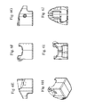
- FIG. 1 is a drawing of a prior art unmodified Colt® M4 5.56 mm Carbine.
- FIG. 2A is a drawing of the top view of a receiver belonging to a prior art unmodified Colt® M4 5.56 mm Carbine.
- FIG. 2B is a drawing of the front view of a receiver belonging to a prior art unmodified Colt® M4 5.56 mm Carbine.
- FIG. 2C is a drawing of the selector side view of a receiver belonging to a prior art unmodified Colt® M4 5.56 mm Carbine.
- FIG. 2D is a drawing of the rear view of a receiver belonging to a prior art unmodified Colt® M4 5.56 mm Carbine.
- FIG. 2E is a drawing of the ejector side view of a receiver belonging to a prior art unmodified Colt® M4 5.56 mm Carbine.
- FIG. 2F is a drawing of the bottom view of a receiver belonging to a prior art unmodified Colt® M4 5.56 mm Carbine.
- FIG. 3A is a drawing of a view of a selector switch sensor and sensor mount appropriate for the Colt® M4 5.56 mm Carbine in accordance with one embodiment of the present invention.
- FIG. 3B is a drawing of the top view of a selector switch sensor and sensor mount appropriate for the Colt® M4 5.56 mm Carbine in accordance with one embodiment of the present invention.
- FIG. 3C is a drawing of a view of a selector switch sensor and sensor mount appropriate for the Colt® M4 5.56 mm Carbine in accordance with one embodiment of the present invention.
- FIG. 3D is a drawing of a view of a selector switch sensor and sensor mount appropriate for the Colt® M4 5.56 mm Carbine in accordance with one embodiment of the present invention.
- FIG. 3E is a drawing of the side view of a selector switch sensor and sensor mount appropriate for the Colt® M4 5.56 mm Carbine in accordance with one embodiment of the present invention.
- FIG. 3F is a drawing of the cross-sectional side view of a selector switch sensor and sensor mount appropriate for the Colt® M4 5.56 mm Carbine in accordance with one embodiment of the present invention.
- FIG. 3G is a drawing of the bottom view of a selector switch sensor and sensor mount appropriate for the Colt® M4 5.56 mm Carbine in accordance with one embodiment of the present invention.
- FIG. 4A is a drawing of the top view of a charger sensor and sensor mount appropriate for the Colt® M4 5.56 mm Carbine in accordance with one embodiment of the present invention.
- FIG. 4B is a drawing of the bottom view of a charger sensor and sensor mount appropriate for the Colt® M4 5.56 mm Carbine in accordance with one embodiment of the present invention.
- FIG. 4C is a drawing of the inside side view of a charger sensor and sensor mount appropriate for the Colt® M4 5.56 mm Carbine in accordance with one embodiment of the present invention.
- FIG. 4D is a drawing of the front view of a charger sensor and sensor mount appropriate for the Colt® M4 5.56 mm Carbine in accordance with one embodiment of the present invention.
- FIG. 4E is a drawing of the rear view of a charger sensor and sensor mount appropriate for the Colt® M4 5.56 mm Carbine in accordance with one embodiment of the present invention.
- FIG. 4F is a drawing of a side view of a charger sensor and sensor mount appropriate for the Colt® M4 5.56 mm Carbine in accordance with one embodiment of the present invention.
- FIG. 4G is a drawing of a side view of a charger sensor and sensor mount appropriate for the Colt® M4 5.56 mm Carbine in accordance with one embodiment of the present invention.
- FIG. 5A is a drawing of a side view of a charger sensor and sensor mount appropriate for the Colt® M4 5.56 mm Carbine in accordance with one embodiment of the present invention.
- FIG. 5B is a drawing of a front view of a charger sensor and sensor mount appropriate for the Colt® M4 5.56 mm Carbine in accordance with one embodiment of the present invention.
- FIG. 5C is a drawing of a top view of a charger sensor and sensor mount appropriate for the Colt® M4 5.56 mm Carbine in accordance with one embodiment of the present invention.
- FIG. 5D is a drawing of a side view of a charger sensor and sensor mount appropriate for the Colt® M4 5.56 mm Carbine in accordance with one embodiment of the present invention.
- FIG. 5E is a drawing of a rear view of a charger sensor and sensor mount appropriate for the Colt® M4 5.56 mm Carbine in accordance with one embodiment of the present invention.
- FIG. 6A is a drawing of a view of a butt stock sensor and sensor mount appropriate for the Colt® M4 5.56 mm Carbine in accordance with one embodiment of the present invention.
- FIG. 6B is a drawing of a rear view of a butt stock sensor and sensor mount appropriate for the Colt® M4 5.56 mm Carbine in accordance with one embodiment of the present invention.
- FIG. 6C is a drawing of a side view of a butt stock sensor and sensor mount appropriate for the Colt® M4 5.56 mm Carbine in accordance with one embodiment of the present invention.
- FIG. 6D is a drawing of a front view of a butt stock sensor and sensor mount appropriate for the Colt® M4 5.56 mm Carbine in accordance with one embodiment of the present invention.
- FIG. 6E is a drawing of a side view of a IR butt stock sensor and sensor mount appropriate for the Colt® M4 5.56 mm Carbine in accordance with one embodiment of the present invention.
- FIG. 6F is a drawing of a front view of a IR butt stock sensor and sensor mount appropriate for the Colt® M4 5.56 mm Carbine in accordance with one embodiment of the present invention.
- FIG. 6G is a drawing of a side view of a IR butt stock sensor and sensor mount appropriate for the Colt® M4 5.56 mm Carbine in accordance with one embodiment of the present invention.
- FIG. 6H is a drawing of a view of a IR butt stock sensor and sensor mount appropriate for the Colt® M4 5.56 mm Carbine in accordance with one embodiment of the present invention.
- FIG. 6I is a drawing of a rear view of a IR butt stock sensor and sensor mount appropriate for the Colt® M4 5.56 mm Carbine in accordance with one embodiment of the present invention.
- FIG. 6J is a drawing of a top view of a IR butt stock sensor and sensor mount appropriate for the Colt® M4 5.56 mm Carbine in accordance with one embodiment of the present invention.
- FIG. 6K is a drawing of a butt stock for the Colt® M4 5.56 mm Carbine with an attached IR sensor and sensor mount and attached butt stock sensor and sensor mount in accordance with one embodiment of the present invention.
- FIG. 7A is a drawing of a top view of an ejector side wiring harness appropriate for the Colt® M4 5.56 mm Carbine in accordance with one embodiment of the present invention.
- FIG. 7B is a drawing of a front view of an ejector side wiring harness appropriate for the Colt® M4 5.56 mm Carbine in accordance with one embodiment of the present invention.
- FIG. 7C is a drawing of a rear view of an ejector side wiring harness appropriate for the Colt® M4 5.56 mm Carbine in accordance with one embodiment of the present invention.
- FIG. 7D is a drawing of a bottom view of an ejector side wiring harness appropriate for the Colt® M4 5.56 mm Carbine in accordance with one embodiment of the present invention.
- FIG. 7E is a drawing of a side view of an ejector side wiring harness appropriate for the Colt® M4 5.56 mm Carbine in accordance with one embodiment of the present invention.
- FIG. 8A is a drawing of a top view of a selector side wiring harness appropriate for the Colt® M4 5.56 mm Carbine in accordance with one embodiment of the present invention.
- FIG. 8B is a drawing of a front view of a selector side wiring harness appropriate for the Colt® M4 5.56 mm Carbine in accordance with one embodiment of the present invention.
- FIG. 8C is a drawing of a side view of a selector side wiring harness appropriate for the Colt® M4 5.56 mm Carbine in accordance with one embodiment of the present invention.
- FIG. 9A is a drawing of a top view of a control unit appropriate for attachment as a forward grip on a rail based mounting system.
- FIG. 9B is a drawing of a view of a control unit appropriate for attachment as a forward grip on a rail based mounting system.
- FIG. 9C is a drawing of a side view of a control unit appropriate for attachment as a forward grip on a rail based mounting system.
- FIG. 9D is a drawing of a front view of a control unit appropriate for attachment as a forward grip on a rail based mounting system.
- FIG. 10 illustrates a flow diagram in accordance with a method of the present invention.
- FIG. 11 is a drawing of potential locations for sensors, sensor attachments and sensor interaction components on the ejector side of a Colt® M4 5.56 mm Carbine in accordance with one embodiment of the present invention.
- FIG. 12 is a drawing of potential locations for sensors, sensor attachments and sensor interaction components on the selector side of a Colt® M4 5.56 mm Carbine in accordance with one embodiment of the present invention.
- FIG. 1 shows a view of the ejector side of an unmodified Colt® M4 5.56 mm Carbine, one of the most commonly used small arms rifle in the United States Armed Forces and many other countries across the world.
- FIGS. 2A-2F shows many views of the receiver of an unmodified Colt® M4 5.56 mm Carbine.
- a weapon such as the Colt® M4 5.56 mm Carbine shown in FIGS. 1 and 2
- the sensors, wiring harness and control unit are communicatively connected in such a manner that various operations of a modified weapon may be processed. Operations include, but are not limited to, selecting a fire rate by changing the position of a selector switch, pulling of a trigger, identification of a firing direction and angle based upon the time a trigger was pulled, use of an ejector.
- the various operations of a modified weapon may be processed and stored in the control unit and/or transmitted via a wireless or wired network connection to a remote computing device (e.g., laptop, server, smartphone, desktop) for processing, storage and analysis.
- a remote computing device e.g., laptop, server, smartphone, desktop
- a remote computing device is able to transmit data to a modified weapon in order to simulate an action or cause the operability of the modified weapon to change.
- simulated actions or operability changes include, but are not limited to, simulation of a misfired round, simulation of a weapon jam, disablement of the weapons capability of firing. These kinds of actions are particularly useful in simulated training systems where the user of a weapon needs to learn how properly respond to these situations.
- sensors numerous types of sensors may be utilized and attached to various components of the weapon.
- sensors that may be utilized in embodiments of the present invention include, but are not limited to, magnetic reed switches, microswitches, photocells and IR detectors.
- FIGS. 3A-3G show multiple views of an exemplary embodiment of a sensor and a sensor attachment for a Colt® M4 5.56 mm Carbine selector switch.
- a magnetic sensor e.g., in the cavity 310 under the dome in FIG. 3G
- a selector switch sensor attachment is contained within a selector switch sensor attachment.
- the selector switch sensor attachment may be attached to a weapon through a variety of means.
- An exemplary embodiment for means of attaching the sensor attachment to a weapon is by way of placing an adhesive compound or tape between the selector switch sensor attachment and the selector switch of the weapon in a manner that does not impede the movement of the selector switch.
- Other means of securing the selector switch sensor attachment to the selector switch include, but are not limited to, “snapping” on a properly sized selector switch sensor attachment to the selector switch of a weapon.
- FIGS. 4A-4G show multiple views of an exemplary embodiment of a sensor and sensor attachment for a Colt® M4 5.56 mm Carbine charger.
- two magnetic sensors are in the L shape region 410 contained within a sensor attachment 430 .
- the charger sensor attachment may be attached to a weapon through a variety of means.
- An exemplary embodiment for means of attaching the charger sensor attachment to a weapon is by way of placing an adhesive compound or tape between the charger sensor attachment and the charger of the weapon in a manner that does not impede the movement of the charger.
- Other means of securing the charger sensor attachment to the charger include, but are not limited to, “snapping” on a properly sized charger sensor attachment to the charger of a weapon.
- FIGS. 5A-5E show multiple views of an exemplary embodiment of a sensor and sensor attachment for a Colt® M4 5.56 mm trigger.
- a microswitch is used as a sensor and is placed under the trigger of a weapon.
- the trigger sensor attachment may be attached to a weapon through a variety of means.
- An exemplary embodiment for means of attaching the trigger sensor attachment to a weapon is by way of placing an adhesive compound or tape between the trigger sensor attachment and the trigger grip of the weapon in a manner that does not impede the movement of the trigger.
- Other means of securing the trigger sensor attachment to the trigger include, but are not limited to, “snapping” on a properly sized trigger sensor attachment to the trigger grip of a weapon.
- FIGS. 6A-6K show multiple views of an exemplary embodiment of a sensor and sensor attachment for a Colt® M4 5.56 mm butt stock.
- a butt stock sensor and sensor attachment 610 and a IR butt stock sensor and sensor attachment 620 work in conjunction to sense if the butt stock is pressed against a user's shoulder or other surface.
- the butt stock sensor attachment 610 and butt stock IR sensor attachment 620 may be attached to a weapon through a variety of means.
- An exemplary embodiment for means of attaching the butt stock sensor attachment 610 and IR butt stock sensor attachment 620 to a weapon is by way of placing a first adhesive compound or tape between the butt stock sensor attachment 610 and the butt stock of the weapon and a second adhesive compound or tape between the IR butt stock sensor attachment 620 and the butt stock of the weapon.
- FIG. 6K shows an exemplary placement of the butt stock sensor attachment 610 and butt stock IR sensor attachment 620 on a butt stock of a weapon.
- sensor locations are just examples of some of the locations to which a sensor and sensor attachment could be affixed.
- One of ordinary skill in the art would understand that there are multiple locations a sensor and sensor attachment could be affixed to a weapon and embodiments of the present invention are contemplated for use with any location on a weapon where a sensor attachment is possible.
- a weapon attachment e.g., an under barrel grenade launcher, any manner of attached optics, etc.
- a component of a weapon attachment e.g., the trigger of an under barrel grenade launcher, etc.
- magazine release button e.g., the trigger of an under barrel grenade launcher, etc.
- a wiring harness is developed by creating a 3D model of a wiring harness appropriate for the weapon that the wiring harness will attach to. Once the 3D model of the wiring harness is created, wire routing and sensor holder pockets are added to the 3D model.
- the wiring harness is formed in such a manner as to attach to the weapon in a non-intrusive manner. It should be understood that non-intrusive means that the wiring harness if formed in such a manner as not to interfere with the usual operation of the weapon (e.g., firing, reloading, spent casing ejection, etc.).
- the wiring harness and second 3D model also have spaces for running data transmission components and sensor interaction components.
- Data transmission components may include, but are not limited to, wires for transmitting data received from the sensors or sensor interaction components to a control unit and wireless data transmission components (e.g., RFID, Bluetooth, wireless network) for transmitting data received from the sensors or sensor interaction components to a control unit.
- Sensor interaction components include, but are not limited to, components capable of detecting changes in magnetic fields, components capable of detecting changes in electrical current, components capable of detecting changes in pressure and components capable of detecting changes in angle/pitch/elevation or other directional positioning.
- FIGS. 7A-7E and 8 A- 8 C An exemplary embodiment of a wiring harness is depicted in FIGS. 7A-7E and 8 A- 8 C.
- FIGS. 7A-7E show a multitude of views of a wiring harness to be mounted on the ejector side of a Colt® M4 5.56 mm Carbine in accordance with one embodiment of the present invention.
- FIGS. 8A-8C show a multitude of views of a wiring harness to be mounted on the selector side of a Colt® M4 5.56 mm Carbine in accordance with one embodiment of the present invention.
- One of ordinary skill in the art would understand that there are various locations acceptable for receiving and securing one or more wiring harnesses on a weapon and embodiments of the present invention are contemplated for use with any location on a weapon where a wiring harness is possible.
- the wiring harness can be designed and attached to a weapon in a manner that acts to protect the weapon from damage and scratches.
- the wiring harness, sensor attachments and control unit can be designed and attached in such a manner as to protect a weapon from damage and scratches, protecting the weapon and potentially extending the life and functionality of the weapon.
- the wiring harness, sensor attachments and/or control unit can have an external shell made from a impact resistant material (e.g., plastic, rubber, silicone) that absorbs shock and wear a weapon may receive from usage.
- a control unit may contain, but is not limited to, components for interacting with simulated straining systems or real world devices (e.g., buttons, dials, joysticks), components for receiving data from sensors or wiring harnesses, components for processing data, components for providing power to the various components of the present invention (e.g., batteries, capacitors) and components for transmitting data to remote computing devices.
- simulated straining systems or real world devices e.g., buttons, dials, joysticks
- components for processing data e.g., components for processing data
- components for providing power to the various components of the present invention e.g., batteries, capacitors
- the control unit may be attached to the weapon in numerous locations, including, but not limited to, mounted to a Picatinny rail. According to an embodiment of the present invention, as depicted in FIGS. 9A-9D , a control unit may take the form of a forward mounted grip.
- a exemplary control unit may consist of a groove 911 capable of attaching to a Picatinny rail or other rail mount system under the barrel of a weapon, a forward grip handle 915 , and a forward control handle 916 .
- the forward grip handle 915 may contain one or more user controls (e.g., buttons, dials, joysticks) that allow for interaction with a simulated training system (e.g., instruct simulated avatar to open a door, mount/dismount a vehicle) or a real world device (e.g., control of a remote controlled vehicle). Actions or events created through the use of the user controls are sent to the components in the control unit that handle processing or transmitting data.
- a simulated training system e.g., instruct simulated avatar to open a door, mount/dismount a vehicle
- a real world device e.g., control of a remote controlled vehicle
- the forward control handle 916 may contain, but is not limited to, components for receiving data from sensors or wiring harnesses, components for processing data 913 , 914 , components for providing power to the various components of the present invention 912 (e.g., batteries, capacitors) and components for transmitting data to remote computing devices 913 , 914 .
- FIG. 10 depicts the flow of an interaction between an exemplary embodiment of the present invention and a simulated training system.
- a weapon in this example a Colt® M4 5.56 mm Carbine, has previously been outfitted with a weapon instrumentation system according in accordance with an embodiment of the present invention as described above.
- the weapon has been modified with at least a magnetic sensor and sensor attachment attached to the selector switch, a wiring harness and a control unit.
- a sensor event occurs.
- the selector switch is changed from its starting point of “safety” to “semi-auto”.
- the change in position of the selector switch also changes the position of the magnetic sensor and sensor attachment causing a sensor event.
- step 1003 the sensor event created in step 1002 is detected.
- the change in the magnetic field caused by the movement of the magnetic sensor and sensor attachment is detected by sensor interaction components in the wiring harness.
- step 1004 the detected sensor event is transmitted to the control unit.
- the data relating to the change in the magnetic field caused by the changing in position of the selector switch is relayed to the control unit via a wired connection between the wiring harness and the control unit.
- the control unit transmits data to a simulated training system.
- the control unit has received data it received from the wiring harness regarding the change in position of the selector switch. This data is then sent wirelessly to a remote computing device that is controlling the simulated training system using a Bluetooth connection.
- the control unit may process and edit the data to be sent.
- a control unit used in this manner will reduce the load on the server(s) of the simulated training system by providing off-board processing of data.
- the simulated training system reacts to the data it has received from the control unit mounted on the modified weapon.
- the simulated training system receives the data pertaining to the change in selector switch position and reacts by noting that the modified weapon is now in a state where it is capable of firing rounds.
- the simulated training system may have ignored any sensor data related to the pulling of the trigger of the modified weapon as the simulated training system registered the modified weapon as in “safety” mode.
- the system and method herein provided has application in live fire exercises and actual field use as well.
- Embodiments of the present invention include control units capable of recording live fire and field use of the modified weapon.
- control unit would record sensor events based on the time they occur. This data may be processed to form an entire timeline of how the weapon was used, including when the weapon was fired, what direction/angle/elevation the weapon was fired in and any other sensor event available to a particular modified weapon.
- the system and method herein described can be used to modify articles of manufacture other than weapons.
- articles of manufacture include, but are not limited to, paintball guns, video game controllers and simulated weapons.
- the resulting modified article of manufacture could be used to interact with a simulated system (e.g., gaming console, simulated training system, remote computing device) or record usage data (e.g., the usage of a paintball gun on a paintball course).
- a simulated system e.g., gaming console, simulated training system, remote computing device
- record usage data e.g., the usage of a paintball gun on a paintball course.
- FIGS. 11 and 12 are included to illustrate possible locations for mounting sensors, sensor attachments and sensor interaction components.
- FIG. 11 shows locations, according to an embodiment of the present invention, for mounting reed switches 1101 inside a selector side wiring harness.
- FIG. 12 shows locations, according to an embodiment of the present invention, for mounting reed switches 1201 , IR detectors 1202 , wiring between the wiring harness and the control unit 1203 , trigger microswitch 1204 and an optical light sensor 1205 .
Landscapes
- Engineering & Computer Science (AREA)
- General Engineering & Computer Science (AREA)
- Toys (AREA)
Abstract
Description
Claims (14)
Priority Applications (1)
| Application Number | Priority Date | Filing Date | Title |
|---|---|---|---|
| US12/785,046 US8528244B2 (en) | 2010-05-21 | 2010-05-21 | System and method for weapons instrumentation technique |
Applications Claiming Priority (1)
| Application Number | Priority Date | Filing Date | Title |
|---|---|---|---|
| US12/785,046 US8528244B2 (en) | 2010-05-21 | 2010-05-21 | System and method for weapons instrumentation technique |
Publications (2)
| Publication Number | Publication Date |
|---|---|
| US20110283586A1 US20110283586A1 (en) | 2011-11-24 |
| US8528244B2 true US8528244B2 (en) | 2013-09-10 |
Family
ID=44971239
Family Applications (1)
| Application Number | Title | Priority Date | Filing Date |
|---|---|---|---|
| US12/785,046 Expired - Fee Related US8528244B2 (en) | 2010-05-21 | 2010-05-21 | System and method for weapons instrumentation technique |
Country Status (1)
| Country | Link |
|---|---|
| US (1) | US8528244B2 (en) |
Cited By (15)
| Publication number | Priority date | Publication date | Assignee | Title |
|---|---|---|---|---|
| US20120329364A1 (en) * | 2009-10-08 | 2012-12-27 | Nimtec As | Electronic Blank Ammunition |
| US20150020427A1 (en) | 2010-01-15 | 2015-01-22 | David Walter Compton | Apparatus and method for powering and networking a rail of a firearm |
| US9823043B2 (en) | 2010-01-15 | 2017-11-21 | Colt Canada Ip Holding Partnership | Rail for inductively powering firearm accessories |
| US9891023B2 (en) | 2010-01-15 | 2018-02-13 | Colt Canada Ip Holding Partnership | Apparatus and method for inductively powering and networking a rail of a firearm |
| US9897411B2 (en) | 2010-01-15 | 2018-02-20 | Colt Canada Ip Holding Partnership | Apparatus and method for powering and networking a rail of a firearm |
| US10337834B2 (en) | 2010-01-15 | 2019-07-02 | Colt Canada Ip Holding Partnership | Networked battle system or firearm |
| US10470010B2 (en) | 2010-01-15 | 2019-11-05 | Colt Canada Ip Holding Partnership | Networked battle system or firearm |
| US10477618B2 (en) | 2010-01-15 | 2019-11-12 | Colt Canada Ip Holding Partnership | Networked battle system or firearm |
| US10477619B2 (en) | 2010-01-15 | 2019-11-12 | Colt Canada Ip Holding Partnership | Networked battle system or firearm |
| US11015890B2 (en) | 2018-10-22 | 2021-05-25 | Magpul Industries Corp. | Determination of round count by hall switch encoding |
| US11329506B2 (en) * | 2019-02-15 | 2022-05-10 | Xentris Wireless, Llc | Modular wireless power bank system |
| US11644278B2 (en) | 2019-12-31 | 2023-05-09 | University Of Central Florida Research Foundation, Inc. | Weapon simulation systems |
| US11719497B2 (en) | 2018-10-22 | 2023-08-08 | Magpul Industries Corp. | Determination of round count by hall switch encoding |
| US11971238B2 (en) | 2018-10-22 | 2024-04-30 | Magpul Industries Corp. | Determination of round count by hall switch encoding |
| US20240139620A1 (en) * | 2022-10-27 | 2024-05-02 | AceXR, LLC | Handgun simulation assembly using virtual reality controller and having a releasable magazine |
Families Citing this family (24)
| Publication number | Priority date | Publication date | Assignee | Title |
|---|---|---|---|---|
| US8656622B2 (en) | 2007-10-11 | 2014-02-25 | Ashbury International Group, Inc. | Tactical firearm systems and methods of manufacturing same |
| US10215529B2 (en) * | 2009-01-16 | 2019-02-26 | Prototype Productions Incorporated Ventures Two, Llc | Accessory mount for rifle accessory rail, communication, and power transfer system—accessory attachment |
| USD676921S1 (en) * | 2011-11-07 | 2013-02-26 | Magpul Industries Corporation | Stock for a firearm |
| USD683808S1 (en) * | 2012-01-27 | 2013-06-04 | Central Pacific Industries (USA) Inc. | Gun stock |
| USD688768S1 (en) | 2012-05-29 | 2013-08-27 | Magpul Industries Corporation | Rifle stock |
| USD692087S1 (en) | 2012-07-31 | 2013-10-22 | Magpul Industries Corporation | Rifle stock |
| US8850735B2 (en) | 2012-10-26 | 2014-10-07 | Ra Brands, L.L.C. | Upper receiver and hand guard with cable routing guide |
| USD710478S1 (en) * | 2013-03-04 | 2014-08-05 | Slide Fire Solutions, Lp | Rifle stock |
| US9395132B2 (en) | 2013-04-01 | 2016-07-19 | Yardarm Technologies, Inc. | Methods and systems for enhancing firearm safety through wireless network monitoring |
| US9404698B2 (en) | 2013-04-01 | 2016-08-02 | Yardarm Technologies, Inc. | Methods and systems for enhancing firearm safety through wireless network monitoring |
| US9958228B2 (en) | 2013-04-01 | 2018-05-01 | Yardarm Technologies, Inc. | Telematics sensors and camera activation in connection with firearm activity |
| US10584940B2 (en) | 2013-05-09 | 2020-03-10 | Shooting Simulator, Llc | System and method for marksmanship training |
| US10274287B2 (en) | 2013-05-09 | 2019-04-30 | Shooting Simulator, Llc | System and method for marksmanship training |
| US10234240B2 (en) | 2013-05-09 | 2019-03-19 | Shooting Simulator, Llc | System and method for marksmanship training |
| US10030937B2 (en) | 2013-05-09 | 2018-07-24 | Shooting Simulator, Llc | System and method for marksmanship training |
| DE102014200530A1 (en) * | 2014-01-14 | 2015-07-16 | Thales Deutschland Gmbh | Firearm with several sensors for detecting an operating state of the firearm |
| USD745627S1 (en) | 2014-07-22 | 2015-12-15 | Magpul Industries Corporation | Folding firearm stock |
| USD765812S1 (en) | 2014-12-22 | 2016-09-06 | Magpul Industries Corporation | Magazine for a firearm |
| USD757884S1 (en) | 2014-12-22 | 2016-05-31 | Magpul Industries Corporation | Firearm magazine |
| EP4119886A1 (en) * | 2017-05-15 | 2023-01-18 | T-Worx Holdings, LLC | Power system for a firearm |
| WO2019161053A2 (en) * | 2018-02-14 | 2019-08-22 | Wilcox Industries Corp. | Weapon system |
| US10969185B2 (en) * | 2019-01-25 | 2021-04-06 | Altered Mechanics | System for simulating the reloading of a magazine in a magazine fed hand operated device for a simulation |
| US20220364817A1 (en) * | 2021-01-27 | 2022-11-17 | Serious Simulations, Llc | Percussive method for capturing data from simulated indirect fire and direct fire munitions for battle effects in live and/or mixed reality training simulations |
| US20250085080A1 (en) * | 2023-09-13 | 2025-03-13 | Wilcox Industries Corp. | Power and data retrofit for weapon accessory rail |
Citations (14)
| Publication number | Priority date | Publication date | Assignee | Title |
|---|---|---|---|---|
| US4416631A (en) | 1982-05-08 | 1983-11-22 | The United States Of America As Represented By The Secretary Of The Navy | Small arms firing effects simulator |
| US20050181335A1 (en) * | 2003-08-01 | 2005-08-18 | Matvey Lvovskiy | Training simulator for sharp shooting |
| US20050191601A1 (en) | 2004-02-26 | 2005-09-01 | Vojtech Dvorak | Training weapon |
| US20080010890A1 (en) * | 2006-07-17 | 2008-01-17 | Vice Jack M | Mounted Isometric Controller |
| US20080032268A1 (en) * | 2006-08-02 | 2008-02-07 | Michael Anthony Farrell | Method and apparatus for monitoring handling of a firearm |
| US7335026B2 (en) * | 2004-10-12 | 2008-02-26 | Telerobotics Corp. | Video surveillance system and method |
| US20080063400A1 (en) | 2006-05-12 | 2008-03-13 | Irobot Corporation | Method and Device for Controlling a Remote Vehicle |
| US20080233543A1 (en) | 2004-06-26 | 2008-09-25 | Avraham Ram Guissin | Video Capture, Recording and Scoring in Firearms and Surveillance |
| US20080282595A1 (en) * | 2007-05-10 | 2008-11-20 | Leitner-Wise Defense, Inc. | Device for Recording and Displaying Data from the Firing of Small-Arms |
| US7568304B1 (en) * | 2003-12-02 | 2009-08-04 | Grip Pod System, Llc | Light rail and accessory rail mount for vertical fore grip |
| US20090255160A1 (en) * | 2008-04-11 | 2009-10-15 | James Summers | Weapon control device |
| US20100031552A1 (en) * | 2008-07-16 | 2010-02-11 | Lasermax, Inc. | Firearm assembly |
| US7661217B2 (en) * | 2006-11-15 | 2010-02-16 | Dov Pikielny | Shot counter |
| US20110162245A1 (en) * | 2010-01-05 | 2011-07-07 | Ibrahim Kamal | Firearm Sensing Device and Method |
-
2010
- 2010-05-21 US US12/785,046 patent/US8528244B2/en not_active Expired - Fee Related
Patent Citations (15)
| Publication number | Priority date | Publication date | Assignee | Title |
|---|---|---|---|---|
| US4416631A (en) | 1982-05-08 | 1983-11-22 | The United States Of America As Represented By The Secretary Of The Navy | Small arms firing effects simulator |
| US20050181335A1 (en) * | 2003-08-01 | 2005-08-18 | Matvey Lvovskiy | Training simulator for sharp shooting |
| US7568304B1 (en) * | 2003-12-02 | 2009-08-04 | Grip Pod System, Llc | Light rail and accessory rail mount for vertical fore grip |
| US20050191601A1 (en) | 2004-02-26 | 2005-09-01 | Vojtech Dvorak | Training weapon |
| US20080233543A1 (en) | 2004-06-26 | 2008-09-25 | Avraham Ram Guissin | Video Capture, Recording and Scoring in Firearms and Surveillance |
| US7335026B2 (en) * | 2004-10-12 | 2008-02-26 | Telerobotics Corp. | Video surveillance system and method |
| US20080063400A1 (en) | 2006-05-12 | 2008-03-13 | Irobot Corporation | Method and Device for Controlling a Remote Vehicle |
| US20090232506A1 (en) | 2006-05-12 | 2009-09-17 | Irobot Corporation | Method and Device for Controlling a Remote Vehicle |
| US20080010890A1 (en) * | 2006-07-17 | 2008-01-17 | Vice Jack M | Mounted Isometric Controller |
| US20080032268A1 (en) * | 2006-08-02 | 2008-02-07 | Michael Anthony Farrell | Method and apparatus for monitoring handling of a firearm |
| US7661217B2 (en) * | 2006-11-15 | 2010-02-16 | Dov Pikielny | Shot counter |
| US20080282595A1 (en) * | 2007-05-10 | 2008-11-20 | Leitner-Wise Defense, Inc. | Device for Recording and Displaying Data from the Firing of Small-Arms |
| US20090255160A1 (en) * | 2008-04-11 | 2009-10-15 | James Summers | Weapon control device |
| US20100031552A1 (en) * | 2008-07-16 | 2010-02-11 | Lasermax, Inc. | Firearm assembly |
| US20110162245A1 (en) * | 2010-01-05 | 2011-07-07 | Ibrahim Kamal | Firearm Sensing Device and Method |
Cited By (21)
| Publication number | Priority date | Publication date | Assignee | Title |
|---|---|---|---|---|
| US20120329364A1 (en) * | 2009-10-08 | 2012-12-27 | Nimtec As | Electronic Blank Ammunition |
| US8770978B2 (en) * | 2009-10-08 | 2014-07-08 | Nimtec As | Electronic blank ammunition |
| US10470010B2 (en) | 2010-01-15 | 2019-11-05 | Colt Canada Ip Holding Partnership | Networked battle system or firearm |
| US10477618B2 (en) | 2010-01-15 | 2019-11-12 | Colt Canada Ip Holding Partnership | Networked battle system or firearm |
| US9879941B2 (en) | 2010-01-15 | 2018-01-30 | Colt Canada Corporation | Method and system for providing power and data to firearm accessories |
| US9891023B2 (en) | 2010-01-15 | 2018-02-13 | Colt Canada Ip Holding Partnership | Apparatus and method for inductively powering and networking a rail of a firearm |
| US9897411B2 (en) | 2010-01-15 | 2018-02-20 | Colt Canada Ip Holding Partnership | Apparatus and method for powering and networking a rail of a firearm |
| US9921028B2 (en) | 2010-01-15 | 2018-03-20 | Colt Canada Ip Holding Partnership | Apparatus and method for powering and networking a rail of a firearm |
| US10060705B2 (en) | 2010-01-15 | 2018-08-28 | Colt Canada Ip Holding Partnership | Apparatus and method for powering and networking a rail of a firearm |
| US10337834B2 (en) | 2010-01-15 | 2019-07-02 | Colt Canada Ip Holding Partnership | Networked battle system or firearm |
| US20150020427A1 (en) | 2010-01-15 | 2015-01-22 | David Walter Compton | Apparatus and method for powering and networking a rail of a firearm |
| US9823043B2 (en) | 2010-01-15 | 2017-11-21 | Colt Canada Ip Holding Partnership | Rail for inductively powering firearm accessories |
| US10477619B2 (en) | 2010-01-15 | 2019-11-12 | Colt Canada Ip Holding Partnership | Networked battle system or firearm |
| US11015890B2 (en) | 2018-10-22 | 2021-05-25 | Magpul Industries Corp. | Determination of round count by hall switch encoding |
| US11719497B2 (en) | 2018-10-22 | 2023-08-08 | Magpul Industries Corp. | Determination of round count by hall switch encoding |
| US11971238B2 (en) | 2018-10-22 | 2024-04-30 | Magpul Industries Corp. | Determination of round count by hall switch encoding |
| US12535283B2 (en) | 2018-10-22 | 2026-01-27 | Magpul Industries Corp. | Determination of round count by hall switch encoding |
| US11329506B2 (en) * | 2019-02-15 | 2022-05-10 | Xentris Wireless, Llc | Modular wireless power bank system |
| US11644278B2 (en) | 2019-12-31 | 2023-05-09 | University Of Central Florida Research Foundation, Inc. | Weapon simulation systems |
| US20240139620A1 (en) * | 2022-10-27 | 2024-05-02 | AceXR, LLC | Handgun simulation assembly using virtual reality controller and having a releasable magazine |
| US12521624B2 (en) * | 2022-10-27 | 2026-01-13 | AceXR, LLC | Handgun simulation assembly using virtual reality controller and having a releasable magazine |
Also Published As
| Publication number | Publication date |
|---|---|
| US20110283586A1 (en) | 2011-11-24 |
Similar Documents
| Publication | Publication Date | Title |
|---|---|---|
| US8528244B2 (en) | System and method for weapons instrumentation technique | |
| US20210199408A1 (en) | Weapon simulation systems | |
| US20080127538A1 (en) | Smart magazine for a weapon simulator and method of use | |
| US20150285593A1 (en) | Monitoring shots of firearms | |
| US11346630B2 (en) | Magazine simulator for usage with weapons in a virtual reality system | |
| US20160209173A1 (en) | Monitoring shots of firearms | |
| US20210270569A1 (en) | Firearm simulation arrangement for a virtual reality system | |
| US20230400277A1 (en) | Haptic system for a firearm simulator | |
| KR101653735B1 (en) | Simulation system including combat training using a practicing-grenade, a practicing-claymore and control keypad for events | |
| WO2022086361A1 (en) | Controller for interacting in virtual reality | |
| US20240247904A1 (en) | Haptic system for a firearm simulator | |
| CN117899476A (en) | Self-aiming technology detection method and device, storage medium and electronic device | |
| EP4022244B1 (en) | Weapon training assembly | |
| US20150306493A1 (en) | System and method for recording objective base capture games, sports, or training exercise statistics | |
| CN116972684A (en) | A simulated training firearm interaction device | |
| KR101155325B1 (en) | The Shooting simulation system using recoil catridge | |
| JP2025535698A (en) | Virtual reality system with attachable sensor system | |
| AU2012101435A4 (en) | Live combat simulation monitoring system, method and apparatus | |
| KR101843757B1 (en) | Miles equipment small arms magazine system | |
| EA041214B1 (en) | VR INTERACTION CONTROLLER | |
| IL308309B2 (en) | Weapon training assembly |
Legal Events
| Date | Code | Title | Description |
|---|---|---|---|
| AS | Assignment |
Owner name: BRAHMA FINANCE BVI LTD, MONACO Free format text: INTELLECTUAL PROPERTY SECURITY AGREEMENT;ASSIGNOR:ATLANTIS CYBERSPACE, INC.;REEL/FRAME:029724/0486 Effective date: 20130128 |
|
| STCF | Information on status: patent grant |
Free format text: PATENTED CASE |
|
| AS | Assignment |
Owner name: SERIOUS SIMULATIONS, LLC, FLORIDA Free format text: ASSIGNMENT OF ASSIGNORS INTEREST;ASSIGNOR:BRAHMA FINANCE (BVI) LTD.;REEL/FRAME:037691/0536 Effective date: 20160127 |
|
| FPAY | Fee payment |
Year of fee payment: 4 |
|
| SULP | Surcharge for late payment | ||
| MAFP | Maintenance fee payment |
Free format text: PAYMENT OF MAINTENANCE FEE, 8TH YR, SMALL ENTITY (ORIGINAL EVENT CODE: M2552); ENTITY STATUS OF PATENT OWNER: SMALL ENTITY Year of fee payment: 8 |
|
| FEPP | Fee payment procedure |
Free format text: MAINTENANCE FEE REMINDER MAILED (ORIGINAL EVENT CODE: REM.); ENTITY STATUS OF PATENT OWNER: SMALL ENTITY |
|
| LAPS | Lapse for failure to pay maintenance fees |
Free format text: PATENT EXPIRED FOR FAILURE TO PAY MAINTENANCE FEES (ORIGINAL EVENT CODE: EXP.); ENTITY STATUS OF PATENT OWNER: SMALL ENTITY |
|
| STCH | Information on status: patent discontinuation |
Free format text: PATENT EXPIRED DUE TO NONPAYMENT OF MAINTENANCE FEES UNDER 37 CFR 1.362 |
|
| FP | Lapsed due to failure to pay maintenance fee |
Effective date: 20250910 |