US8525957B2 - Display apparatus, electronic equipment, mobile electronic equipment, mobile telephone, and image pickup apparatus - Google Patents
Display apparatus, electronic equipment, mobile electronic equipment, mobile telephone, and image pickup apparatus Download PDFInfo
- Publication number
- US8525957B2 US8525957B2 US13/065,831 US201113065831A US8525957B2 US 8525957 B2 US8525957 B2 US 8525957B2 US 201113065831 A US201113065831 A US 201113065831A US 8525957 B2 US8525957 B2 US 8525957B2
- Authority
- US
- United States
- Prior art keywords
- light exit
- display apparatus
- exit point
- lens
- sub
- Prior art date
- Legal status (The legal status is an assumption and is not a legal conclusion. Google has not performed a legal analysis and makes no representation as to the accuracy of the status listed.)
- Expired - Fee Related, expires
Links
Images


Classifications
-
- G—PHYSICS
- G02—OPTICS
- G02B—OPTICAL ELEMENTS, SYSTEMS OR APPARATUS
- G02B27/00—Optical systems or apparatus not provided for by any of the groups G02B1/00 - G02B26/00, G02B30/00
- G02B27/10—Beam splitting or combining systems
- G02B27/12—Beam splitting or combining systems operating by refraction only
- G02B27/123—The splitting element being a lens or a system of lenses, including arrays and surfaces with refractive power
-
- G—PHYSICS
- G02—OPTICS
- G02B—OPTICAL ELEMENTS, SYSTEMS OR APPARATUS
- G02B27/00—Optical systems or apparatus not provided for by any of the groups G02B1/00 - G02B26/00, G02B30/00
- G02B27/10—Beam splitting or combining systems
- G02B27/1066—Beam splitting or combining systems for enhancing image performance, like resolution, pixel numbers, dual magnifications or dynamic range, by tiling, slicing or overlapping fields of view
-
- G—PHYSICS
- G02—OPTICS
- G02B—OPTICAL ELEMENTS, SYSTEMS OR APPARATUS
- G02B5/00—Optical elements other than lenses
- G02B5/20—Filters
- G02B5/201—Filters in the form of arrays
-
- G—PHYSICS
- G02—OPTICS
- G02C—SPECTACLES; SUNGLASSES OR GOGGLES INSOFAR AS THEY HAVE THE SAME FEATURES AS SPECTACLES; CONTACT LENSES
- G02C7/00—Optical parts
- G02C7/16—Shades; shields; Obturators, e.g. with pinhole, with slot
-
- G—PHYSICS
- G02—OPTICS
- G02F—OPTICAL DEVICES OR ARRANGEMENTS FOR THE CONTROL OF LIGHT BY MODIFICATION OF THE OPTICAL PROPERTIES OF THE MEDIA OF THE ELEMENTS INVOLVED THEREIN; NON-LINEAR OPTICS; FREQUENCY-CHANGING OF LIGHT; OPTICAL LOGIC ELEMENTS; OPTICAL ANALOGUE/DIGITAL CONVERTERS
- G02F1/00—Devices or arrangements for the control of the intensity, colour, phase, polarisation or direction of light arriving from an independent light source, e.g. switching, gating or modulating; Non-linear optics
- G02F1/01—Devices or arrangements for the control of the intensity, colour, phase, polarisation or direction of light arriving from an independent light source, e.g. switching, gating or modulating; Non-linear optics for the control of the intensity, phase, polarisation or colour
- G02F1/13—Devices or arrangements for the control of the intensity, colour, phase, polarisation or direction of light arriving from an independent light source, e.g. switching, gating or modulating; Non-linear optics for the control of the intensity, phase, polarisation or colour based on liquid crystals, e.g. single liquid crystal display cells
- G02F1/133—Constructional arrangements; Operation of liquid crystal cells; Circuit arrangements
- G02F1/1333—Constructional arrangements; Manufacturing methods
- G02F1/1335—Structural association of cells with optical devices, e.g. polarisers or reflectors
- G02F1/133526—Lenses, e.g. microlenses or Fresnel lenses
-
- G—PHYSICS
- G02—OPTICS
- G02B—OPTICAL ELEMENTS, SYSTEMS OR APPARATUS
- G02B27/00—Optical systems or apparatus not provided for by any of the groups G02B1/00 - G02B26/00, G02B30/00
- G02B27/0075—Optical systems or apparatus not provided for by any of the groups G02B1/00 - G02B26/00, G02B30/00 with means for altering, e.g. increasing, the depth of field or depth of focus
-
- G—PHYSICS
- G02—OPTICS
- G02F—OPTICAL DEVICES OR ARRANGEMENTS FOR THE CONTROL OF LIGHT BY MODIFICATION OF THE OPTICAL PROPERTIES OF THE MEDIA OF THE ELEMENTS INVOLVED THEREIN; NON-LINEAR OPTICS; FREQUENCY-CHANGING OF LIGHT; OPTICAL LOGIC ELEMENTS; OPTICAL ANALOGUE/DIGITAL CONVERTERS
- G02F1/00—Devices or arrangements for the control of the intensity, colour, phase, polarisation or direction of light arriving from an independent light source, e.g. switching, gating or modulating; Non-linear optics
- G02F1/01—Devices or arrangements for the control of the intensity, colour, phase, polarisation or direction of light arriving from an independent light source, e.g. switching, gating or modulating; Non-linear optics for the control of the intensity, phase, polarisation or colour
- G02F1/13—Devices or arrangements for the control of the intensity, colour, phase, polarisation or direction of light arriving from an independent light source, e.g. switching, gating or modulating; Non-linear optics for the control of the intensity, phase, polarisation or colour based on liquid crystals, e.g. single liquid crystal display cells
- G02F1/133—Constructional arrangements; Operation of liquid crystal cells; Circuit arrangements
- G02F1/1333—Constructional arrangements; Manufacturing methods
- G02F1/1335—Structural association of cells with optical devices, e.g. polarisers or reflectors
- G02F1/133509—Filters, e.g. light shielding masks
- G02F1/133512—Light shielding layers, e.g. black matrix
-
- G—PHYSICS
- G02—OPTICS
- G02F—OPTICAL DEVICES OR ARRANGEMENTS FOR THE CONTROL OF LIGHT BY MODIFICATION OF THE OPTICAL PROPERTIES OF THE MEDIA OF THE ELEMENTS INVOLVED THEREIN; NON-LINEAR OPTICS; FREQUENCY-CHANGING OF LIGHT; OPTICAL LOGIC ELEMENTS; OPTICAL ANALOGUE/DIGITAL CONVERTERS
- G02F2201/00—Constructional arrangements not provided for in groups G02F1/00 - G02F7/00
- G02F2201/52—RGB geometrical arrangements
-
- G—PHYSICS
- G03—PHOTOGRAPHY; CINEMATOGRAPHY; ANALOGOUS TECHNIQUES USING WAVES OTHER THAN OPTICAL WAVES; ELECTROGRAPHY; HOLOGRAPHY
- G03B—APPARATUS OR ARRANGEMENTS FOR TAKING PHOTOGRAPHS OR FOR PROJECTING OR VIEWING THEM; APPARATUS OR ARRANGEMENTS EMPLOYING ANALOGOUS TECHNIQUES USING WAVES OTHER THAN OPTICAL WAVES; ACCESSORIES THEREFOR
- G03B2217/00—Details of cameras or camera bodies; Accessories therefor
- G03B2217/18—Signals indicating condition of a camera member or suitability of light
Definitions
- the present invention relates to a display apparatus, and an electronic equipment, a mobile electronic equipment, a mobile telephone, and an image pickup apparatus which include the display apparatus.
- display apparatuses such as a liquid crystal display and a plasma display are available.
- these display apparatuses have a drawback that diopter adjustment is not available.
- FPD flat-panel display
- a use of electronic books instead of paper books has been increasing. It is extremely cumbersome to put on or take off reading glasses every time at the time of looking at the FPD of a mobile equipment such as a mobile telephone and a digital camera.
- a display apparatus includes
- the black matrix has a plurality of light exit points which transmit light
- a light exit point group includes at least one light exit point
- the display apparatus has a plurality of lenses which project the light exit point group
- the plurality of lenses project images of the light exit point groups to be overlapped
- projected images of the plurality of lenses are formed on a retina of an eye of an observer by inducing overlapping of light exit points in the light exit point group, which have been projected by the lenses to be overlapped, on a pupil of the eye of the observer.
- a size of the image of the light exit point projected by the lens is smaller than a diameter of the pupil of the eye of the observer.
- an electronic equipment includes a display apparatus according to the present invention.
- a mobile electronic equipment includes the display apparatus according to the present invention.
- a mobile telephone includes the display apparatus according to the present invention.
- an image pickup apparatus includes a display apparatus according to the present invention.
- FIG. 1 is a perspective view showing a structure of a display apparatus according to a first embodiment of the present invention
- FIG. 2 is a diagram showing a part of an optical system of the display apparatus according to the first embodiment
- FIG. 3A , FIG. 3B and FIG. 3C show diagrams that compare the image formed by a light beam passed through an entire pupil of an eye with the image formed by a light beams smaller than the pupil.
- FIG. 4 is a perspective view showing a structure of a display apparatus according to another pattern of the first embodiment
- FIG. 5 is a perspective view showing a structure of a display apparatus according to still another pattern of the first embodiment
- FIG. 6A and FIG. 6B are diagrams showing a state in which a plurality of light exit points is projected on a pupil of an observer
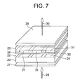
- FIG. 7 is a perspective view showing a pixel structure of a liquid crystal display
- FIG. 8 is an exploded perspective view showing a pixel structure of the first embodiment
- FIG. 9 is a plan view showing a structure of a black matrix of the first embodiment.
- FIG. 10 is a cross-sectional view showing a structure of light exit points provided for the black matrix of the first embodiment
- FIG. 11A is a perspective view showing a combined micro lens array and a black matrix corresponding to a plurality of pixels
- FIG. 11B is a plan view showing a structure of light exit point groups in FIG. 11A ;
- FIG. 12 is a diagram showing a structure of a display apparatus according to a second embodiment of the present invention.
- FIG. 13 is a diagram showing the display apparatus according to the second embodiment, and a picture image which is observed by the display apparatus according to the second embodiment;
- FIG. 14 is a diagram showing a structure of a display apparatus according to a third embodiment of the present invention.
- FIG. 15 is a diagram showing the display apparatus according to the third embodiment, and a picture image which is observed by the display apparatus according to the third embodiment;
- FIG. 16 is a diagram showing a structure of a display apparatus according to another pattern of the third embodiment.
- FIG. 17 is a diagram showing a structure of a display apparatus according to a fourth embodiment of the present invention.
- FIG. 18 is a diagram showing the display apparatus according to the fourth embodiment, and a picture image which is observed by the display apparatus according to the fourth embodiment;
- FIG. 19 is a perspective view showing a pixel arrangement for a color display of a liquid crystal display
- FIG. 20 is a perspective view showing a pixel arrangement for the color display of the liquid crystal display
- FIG. 21 is a diagram showing an example of a diagonal arrangement of sub-information pixels for a color display according to a fifth embodiment of the present invention.
- FIG. 22 is a diagram showing an example of a delta arrangement of sub-information pixels for a color display according to the fifth embodiment of the present invention.
- FIG. 23 is a perspective view showing a digital camera according to a sixth embodiment of the present invention.
- FIG. 24 is a perspective view showing a mobile telephone according to a seventh embodiment of the present invention.
- the present invention provides a display apparatus in which a pupil of an eye is narrowed equivalently, and an electronic equipment, a mobile electronic equipment, a mobile telephone and an image pickup apparatus which include the display apparatus.
- FIG. 1 shows a display principle of a display apparatus according to embodiments of the present invention.
- FIG. 1 is a perspective view showing a basic structure of the display apparatus according to the embodiments.
- a lens 3 is a lens of an eye of a person who observes a display (an observer), and an aperture of the lens 3 is a pupil 3 a .
- Light exit point groups 1 a , 1 b and 1 c may include at least one light exit point.
- each of the light exit point groups 1 a , 1 b and 1 c includes one light exit point, description will be made by calling the light exit point group as a light exit point.
- the display apparatus includes light exit point groups (light exit points) 1 a , 1 b and 1 c , and lenses 2 a , 2 b and 2 c.
- a size 4 of the light exit points 1 a , 1 b and 1 c projected on the pupil 3 a is set smaller than a diameter of the pupil 3 a .
- light beam (the size 4 ) passing through the pupil 3 a is smaller than the pupil 3 a.
- the lenses 2 a , 2 b and 2 c are projected on a retina 5 by the lens 3 of the eye, and their images 6 a , 6 b and 6 c are formed.
- the lens images 6 a , 6 b and 6 c become images of pixels.
- a signal of a picture image i.e. video signal
- FIG. 2 is a diagram showing a part of an optical system of the display apparatus having a basic structure.
- the light exit point 1 is one of the light exit points 1 a , 1 b and 1 c ( FIG. 1 )
- the lens 2 is one of the lenses 2 a , 2 b and 2 c ( FIG. 1 ).
- the light exit point 1 is shown as a micro area having a finite area.
- the light exit point 1 is projected on the lens 3 of the eye by the lens 2 .
- Light which has emerged from a point 9 a on the light exit point 1 becomes a light beam shown by light beams 7 a and 7 b (solid lines) after passing through the lens 2 .
- an image 10 a of the point 9 a is formed on the lens 3 of the eye by the light beams 7 a and 7 b.
- the lens 2 is formed as an image in the proximity 5 ′ of the retina 5 by the lens 3 of the eye.
- a point 2 U of the lens 2 is formed as an image in the proximity 5 a of the retina 5 as shown by light beams 7 a , 8 a , 7 c and 8 c .
- a point 2 L of the lens 2 is formed as an image in the proximity 5 b of the retina 5 , as shown by light beams 7 b , 8 b , 7 d and 8 d .
- an image 6 of the lens 2 is formed in the proximity 5 ′ of the retina 5 .
- a focal length of the lens 2 is so short that a focal depth of the image 4 of the light exit point group projected on the pupil 3 a of the eye of the observer is deep. Therefore, it is in small need that the focusing is accurate on the pupil 3 a.
- FIG. 3A , FIG. 3B and FIG. 3C are diagrams comparing the image by a light beam transmitted through the entire pupil 3 a of the lens of the eye to the image by a light beams formed by an image of a light exit point smaller than the pupil 3 a forms.
- FIG. 3A is a diagram showing a part of the optical system of the display apparatus having the basic structure
- FIG. 3B is a diagram showing an image formed on the retina 5
- FIG. 3C is a diagram showing light beams 11 and 12 on the pupil 3 a.
- a display method is the method of increasing a depth of field by bringing the pupil 3 a in a narrowed state equivalently, by making a light beam thinner than the pupil 3 a incident on the pupil 3 a.
- the light exit points 1 a , 1 b and 1 c in FIG. 1 are light transmission portions (a color filter 34 as a light exit point) of a black matrix, which will be described by referring to FIG. 8 and FIG. 9 .
- the light exit point is not necessarily a point, and may be an area having a finite area. Moreover, it is preferable that the light exit point and the light transmission point have a circular shape as in FIG. 1 , but may not be necessarily round.
- pixels (pixels formed by pixel electrodes) of a normal LCD are called information pixels in order to distinguish themselves from lenses which are the pixels of the embodiment.
- the information pixels may be associated with the light exit points on one-to-one basis, or a plurality of light exit points may be provided to one information pixel. An example of providing the plurality of light exit points to one information pixel is shown in FIG. 5 .
- a color display is carried out by composing one information pixel of sub-information pixels of R (red), G (green) and B (blue). It is possible to have a color display of R, G and B by associating the light exit points 1 a , 1 b and 1 c with sub-information pixels.
- the light beam (of size 4 ) smaller than the diameter of the pupil 3 a is made to be incident on the pupil 3 a , brightness is reduced by the amount equivalent to the reduction in the diameter of the light beam.
- it is desirable to increase luminance of the information pixels for example, to increase luminance (brightness) of a liquid crystal panel. It is desirable to use a LED (light emitting diode) or a LD (laser diode) as a backlight source.
- FIG. 4 is a perspective view showing another basic structure.
- the light exit points 1 a , 1 b and 1 c are disposed at the same interval as the interval of the lenses 2 a , 2 b and 2 c which are pixels. Consequently, lights emerged from the light exit points 1 a , 1 b and is are projected on the pupil 3 a of the lens 3 of the eye of the observer by the lenses 2 a , 2 b and 2 c , but images of the lights are not overlapped.
- a field lens 15 makes the images of the light exit points 1 a , 1 b and 1 c to be overlapped on the pupil 3 a of the lens 3 of the eye. In this manner, in a case of letting the light exit points and the lenses have the same interval, it is necessary to use a field lens.
- FIG. 5 is a perspective view showing another basic structure.
- a display apparatus shown in FIG. 5 includes lenses 2 a , 2 b and 2 c which are pixels, and light exit point groups 16 a , 16 b and 16 c .
- the light exit point groups 16 a , 16 b and 16 c include a plurality of light exit points 18 a , 18 b and 18 c respectively.
- the light exit point groups 16 a , 16 b and 16 c correspond to information pixels or sub-information pixels.
- the light exit point groups 16 a , 16 b and 16 c seem to be corresponding with the lenses 2 a , 2 b and 2 c respectively on one-to-one basis
- the light exit point groups 16 a and 16 b correspond to the lenses 2 b and 2 c .
- the interval of the lenses is Lp and the interval of the light exit point groups is Pp.
- the number of light exit points in each light exit point group may be one as mentioned above ( FIG. 1 and FIG. 4 ).
- Each of the light exit point groups 16 a , 16 b and 16 c is projected by the lens 2 b . Accordingly, light exit point group images 17 a , 17 b and 17 c are formed ( FIG. 5 ).
- the light exit point group 16 a is projected at a position of the light exit point group image 17 b and the light exit point group 16 b is projected at a position of the light exit point group image 17 c.
- the lens 2 c the light exit point group 16 b is projected at a position of the light exit point group image 17 a and the light exit point group 16 c is projected at the position of the light exit point group image 17 b.
- images of the light exit points 18 a , 18 b and 18 c are projected to be overlapped on the pupil 3 a , by the lenses 2 a , 2 b and 2 c.
- projected images 19 a , 19 b and 19 c of the lenses 2 a , 2 b and 2 c are formed on the retina 5 of the lens 3 of the eye.
- FIG. 6A and FIG. 6B are diagrams showing a state in which the plurality of light exit points is projected on the pupil 3 a of the observer.
- the description will be made upon assuming that the light exit point 18 a in FIG. 5 has been projected.
- a projected image 20 is an image of the light exit point 18 a on the pupil 3 a.
- the projected image 20 on the pupil 3 a is of an appropriate size with respect to the pupil 3 a of the observer's eye, an image of one light exit point (an image of a size smaller than the pupil 3 a ) is formed on the pupil 3 a .
- the projected image 20 on the pupil 3 a of the light exit point corresponds to a size of the light beams 13 and 14 on the pupil 3 a in FIG. 3A , FIG. 3B and FIG. 3C , and also corresponds to spreading on the retina 5 .
- the diameter of a light beam incident on the pupil 3 a of the observer is smaller than the diameter of the pupil 3 a .
- the projected image of the light exit point by the lens is smaller than the diameter of the pupil, it takes an effect in which the depth of field is increased.
- the diameter of the pupil 3 a in a normal brightness is about 3 mm, it is preferable that the diameter of the light beam (size, diameter of the image of the light exit point) is 2.8 mm or less for increasing the depth of field.
- the resolving power (a diffraction limit) of 2 mm diameter of a light beam corresponds to almost an eyesight of 1.0 when the wavelength is 0.55 ⁇ m.
- the eyesight is degraded to 0.5.
- there is a resolving power of about 0.17 at a point 300 mm from the observer there is no problem.
- the diameter of the light beam is narrowed down to 0.5 mm, the eyesight is degraded down to 0.25.
- the resolving power 300 mm ahead is degraded to 0.33 mm. With this level, it is somewhat possible to see characters of about 3 mm.
- the diameter of the light beam is narrowed down to 0.2 mm, the eyesight is degraded to 0.1, and the resolving power 300 mm ahead is degraded to 0.9 mm. Consequently, the diameter of the light beam can be narrowed down to about 0.5 mm at the least.
- an intensity distribution of a projected image of a light exit point is not clear due to factors such as diffraction.
- the size of the projected image can be considered to be full width at half maximum equivalently.
- a distance at which a farsighted person has a difficulty in seeing an object is a short distance in many cases. Therefore, in order that it is easy to see an object at a distance of about 300 mm, it is preferable to project an image of the light exit point 300 mm ahead assuming the distance up to the observer to be 300 mm. According to an application, even shorter distance may be taken into consideration. For having the effect of increase in the depth of field, it is preferable to set a projected size of the light exit point to about 2.8 mm or less than 2.8 mm.
- each of the diameter of the lens corresponds to the size of a pixel, 500 ⁇ m or smaller is preferable for a highly defined display. Furthermore, the resolving power, when a person having an eyesight of 1.0 sees an object 300 mm away, is approximately 0.1 mm, and it is preferable that the size of the lens (lenses 2 a , 2 b and 2 c ) is half of that, which is 0.05 mm, or in other words, about 50 ⁇ m. On the other hand, it is necessary to take into consideration, spreading of a light beam due to diffraction as well.
- a spreading angle ⁇ by diffraction, when let D be the size of the aperture (or a diameter or a length of one side), is substantially expressed by the following expression (3). ⁇ ⁇ / D (3)
- the size of the lens is 50 ⁇ m or more.
- the size of the lens for maintaining the size of the light beam to be 1 mm on the pupil 3 a is 165 ⁇ m when the distance of observation is 300 mm. Accordingly, it is desirable that the size of the lens is in a range of 50 ⁇ m to 500 ⁇ m.
- FIG. 7 is a perspective view showing a structure of an information pixel of the normal liquid crystal display.
- a polarizing plate 27 a glass substrate 23 , a liquid crystal layer 22 , a glass substrate 25 and a polarizing plate 29 are disposed in order from a side of incidence to a side of output.
- a pixel electrode 24 which is transparent is composed on a surface of the glass substrate 23 , toward the liquid crystal layer 22 .
- a color filter 31 of R (red), G (green) and B (blue), and a common electrode 26 are composed in order on a surface of the glass substrate 25 , toward the liquid crystal layer 22 , thereby making the color display possible. Consequently, the liquid crystal layer 22 is sandwiched between the transparent pixel electrode 24 provided to the glass substrate 23 and the transparent common electrode 26 provided to the glass substrate 25 .
- the glass substrate 25 is provided with a black matrix 32 for improving a contrast.
- a colorless portion is provided between filters of different colors, and these portions compose the black matrix 32 . Since the color filters 31 of R, G and B are not in contact with each other because of the presence of the black matrix 32 , it is possible to prevent mixing of colors.
- the black matrix 32 is also useful for preventing light leakage at the time of black display, in addition to preventing mixing of colors. Moreover, the black matrix 32 has a function of preventing a leakage of current from a TFT (thin film transistor) not shown in the diagram, which drives the pixel electrodes.
- TFT thin film transistor
- FIG. 8 is an exploded perspective view showing a structure of an information pixel in the display apparatus according to the first embodiment.
- FIG. 9 is a plan view showing a structure of a black matrix.
- FIG. 10 is a cross-sectional view showing a structure of the color filter 34 provided as a light exit point to the black matrix 32 .
- the information pixel in the display apparatus similarly as the liquid crystal display shown in FIG. 7 , includes the polarizing plate 27 , the glass substrate 23 , the liquid crystal layer 22 , the glass substrate 25 and the polarizing plate 29 , which are disposed in the abovementioned order from a side of incidence of light to an output side of light.
- the black matrix 32 and the color filter 34 which becomes the light exit point are provided on the glass substrate 25 .
- the black matrix 32 and the color filter 34 are protected by a protective layer 35 , and the common electrode 26 is provided on the protective layer 35 .
- the black matrix 32 As a material of the black matrix 32 , a material such as a resin material which includes chromium or carbon black is used.
- the black matrix 32 may have a color other than black, if it is thin and has a superior light shielding property.
- lenses of a micro lens array 33 are provided at an output side of the polarizing plate 29 .
- Each lens of the micro lens array 33 corresponds to a sub-information pixel, and each lens is disposed corresponding to the pixel electrode 24 .
- R, G and B of the color filter 34 is not restricted to an order shown in FIG. 10 , and R, G and B of the color filter 34 may be disposed in a different order.
- a combined micro lens array which is imparted an effect of the field lens is used instead of the micro lens array 33 .
- FIG. 11A is a perspective view showing the black matrix 32 and a combined micro lens array 36
- FIG. 11B is a plan view showing an arrangement of light exit point groups of the black matrix 32 .
- FIG. 11A and FIG. 11B details of the pixel structure are omitted.
- the diagram is drawn as if there is a gap between the light exit point groups of the black matrix 32 for convenience of explanation, there is no unnecessary gap in a practical arrangement.
- an interval of the sub-information pixels (an interval of the light exit points on the black matrix 32 ) and an interval of the combined micro lens array 36 are set to be the same.
- the information pixel of the black matrix 32 includes sub-information pixels 32 R, 32 G and 32 B ( FIG. 11B ).
- Each of the sub-information pixels 32 R, 32 G and 32 B is rectangular-shaped, and corresponds to R, G and B respectively.
- Such arrangement corresponds to an arrangement of colors in a color display of a stripe type.
- At least one light exit point 37 , 38 and 39 has been provided in the sub-information pixels 32 R, 32 G and 32 B respectively.
- three light exit points are provided to each sub-information pixel.
- an arrangement of the light exit points 37 , 38 and 39 is same in all the sub-information pixels. By such an arrangement, the sub-information pixels compose a new light exit point group.
- the field lens effect becomes unnecessary, and a micro lens array is used instead of the combined micro lens array 36 .
- the information pixel has a square shape in a large number of cases, and the rectangular-shaped sub information pixels of R, G and B have a horizontal width 1 ⁇ 3 times of a vertical width.
- the size of a rectangular-shaped lens corresponding to the sub-information pixel is 60 ⁇ m ⁇ 180 ⁇ m.
- a diameter of a light beam of a light exit point projected by the rectangular-shaped lens is spread by diffraction, and is 2.75 mm approximately. The spread diameter being smaller than the pupil diameter of 3 mm of a normal eye, there is an effect of increase in the depth of field.
- one more color to R, G and B may be added.
- Lenses in the numerical examples indicate lenses 2 a , 2 b and 2 c in cases of FIG. 1 , FIG. 4 and FIG. 5 , and indicate the combined micro lens array 36 in cases of FIG. 11A and FIG. 11B .
- the projection magnification of the lens is 500 times. If the distance up to the observer is 300 mm, the focal length of the lens is 0.599 mm. The light exit point is placed at a rear focal point position 0.6 mm. In a case of projecting 300 mm ahead due to the focal length of the lens being small, projection is almost same as an infinite projection. If an interval between the nearest light exit points is 6 ⁇ m, the interval is 3 mm at a position of the observer. If the pupil is moved 3 mm, an image is seen by a light beam by a projected image of an adjacent light exit point.
- the projection magnification of the lens is 300 times. If the distance up to the observer is 300 mm, the focal length of the lens is 0.997 mm. The light exit point is placed at the rear focal point position 1.0 mm. If an interval between the nearest light exit points is 10 ⁇ m, the interval is 3 mm at the position of the observer. If the pupil is moved 3 mm, an image is seen by a light beam by a projected image of the adjacent light exit point.
- the projection magnification of the lens is 200 times. If the distance up to the observer is 300 mm, the focal length of the lens is 1.49 mm. The light exit point is placed at the rear focal point position 1.5 mm. If the interval between the nearest light exit points is 15 ⁇ m, the interval is 3 mm at the position of the observer. If the pupil is moved 3 mm, an image is seen by a light beam by a projected image of the adjacent light exit point.
- the projection magnification of the lens is 100 times. If the distance up to the observer is 300 mm, the focal length of the lens is 2.97 mm. The light exit point is placed at the rear focal point position 3.0 mm. When the interval between the nearest light exit points is 30 ⁇ m, the interval is 3 mm at the position of the observer. If the pupil is moved 3 mm, an image is seen by a light beam by a projected image of the adjacent light exit point.
- the size of the light exit point is 10 ⁇ m, for making a projected image of 1.25 mm incident on the pupil of the observer, it is necessary that the projection magnification of the lens is 125 times. If the distance up to the observer is 250 mm, the focal length of the lens is 1.98 mm. The light exit point is placed at the rear focal point position 2.0 mm.
- the size of the light exit point is 20 ⁇ m, for making a projected image of 1 mm incident on the pupil of the observer, it is necessary that the projection magnification of the lens is 50 times. If the distance up to the observer is 300 mm, the focal length of the lens is 5.88 mm. The light exit point is placed at the rear focal point position 6.0 mm.
- the display apparatus and an electronic equipment, a mobile electronic equipment, a mobile telephone and an image pickup apparatus, which include the display apparatus, have an effect that a focal depth of the eye is increased by making a light beam incident on the pupil of the observer smaller than the diameter of the pupil. As a result, it is possible to increase the depth of field, and even a person who is not capable of focusing at a display position is able to see a focused display.
- the display apparatus and the electronic equipment, the mobile electronic equipment, the mobile telephone and the image pickup apparatus, which include the display apparatus, even a farsighted person due to old age is able to see a focused display without putting on or taking off reading glasses. Furthermore, a load on eyes of a farsighted observer due to old age is reduced, and it is possible to observe without using reading glasses or any other optical member. Consequently, even a farsighted person due to old age is capable of seeing without putting on or taking off reading glasses, a focused display of a mobile equipment such as a mobile telephone, a digital camera, and an electronic book, and monitor screens such as a car navigation system and a personal computer, in which the display apparatus according to the first embodiment is used.
- a farsighted person or a nearsighted person is able to see a focused image including any information which is displayed, such as pictures and characters, without using glasses. Therefore, even a farsighted person due to old age, a nearsighted person, or an astigmatic person, who has a difficulty in seeing a display with a normal electronic equipment is able to recognize display contents by a focused display, and to operate the equipment accurately.
- the size of one side of the information pixel is about 90 ⁇ m.
- the sub-information pixel has a rectangular shape of 30 ⁇ m ⁇ 90 ⁇ m. If a lens is made smaller corresponding to such sub-information pixel, a problem that a projected image of a diameter smaller than the pupil of the eye cannot be formed arises due to spreading caused by diffraction of a projected image of the light exit point.
- FIG. 12 shows an example in which an information pixel consists of two sub-information pixels is associated with one lens.
- FIG. 12 is a diagram showing a structure of a display apparatus according to a second embodiment.
- FIG. 13 is a diagram showing the display apparatus according to the second embodiment, and an image which is observed by the display apparatus according to the second embodiment.
- An information pixel 40 of a liquid crystal display includes sub-information pixels having a rectangular shape.
- Each of the sub-information pixels is assigned one of R, G and B colors, and the sub-information pixels are arranged in order of R 1 , G 1 , B 1 , R 2 , G 2 , B 2 , R 3 , G 3 , B 3 , R 4 , G 4 and B 4 .
- the order of R, G and B of the sub-information pixels is repeated, but it may be a repetition of an order other than R, G and B of the sub-information pixels.
- At least one light exit point is provided on these sub-information pixels.
- the size and shape of the lens are the same size and shape of the combined two sub-information pixels which compose the information pixel.
- the light exit point is a color filter provided to the black matrix as it has already been mentioned.
- two adjacent sub-information pixels B 1 and R 2 compose one information pixel, and this information pixel composes one light exit point group.
- one lens 43 a is disposed at a position facing this information pixel.
- sub-information pixels G 2 and B 2 correspond to a lens 43 b
- sub-information pixels R 3 and G 3 correspond to a lens 43 c .
- the correspondence other than this is as shown in FIG. 12 .
- an image of a light exit point is projected in the proximity 44 of a pupil 45 of an eye by a field lens 42 and a micro lens array 41 including lenses 43 a , 43 b and 43 c .
- Projected images R 3 , B 2 , G 2 and R 2 by the lens 43 b and projected images B 3 , G 3 , R 3 and B 2 by the lens 43 c are formed corresponding to positions of projected images G 2 , R 2 , B 1 and G 1 by the lens 43 a .
- the projected images are formed with overlapping the images of the sub-information pixels in original arrangement shifted by two sub-information pixels.
- the projected images are formed with overlapping the arrangement for each color shifted by two in unit of light exit point in the sub-information pixel.
- R, G and B are overlapped in one projected image.
- a light exit point group consists of two sub-information pixels, which are of different colors and overlapped in the projected image, is associated with a lens. Consequently, even if a projected image of any light exit point is incident on the pupil, light beams of R, G and B can be incident on the pupil and a color image can be seen.
- the projected images of the light exit points projected on the pupil 45 of the eye are R 2 , B 2 and G 3 , an image 46 shown in FIG. 13 is observed on the retina.
- the pixel observed on the retina is a lens.
- light beams from the sub-information pixels R 2 , B 2 and G 3 pass through the lenses 43 a , 43 b and 43 c . Therefore, when the lenses 43 a , 43 b and 43 c are formed as images on the retina, images of R, G and B are formed. In other words, the observer can see a color image of R, G and B.
- the sub-information pixel of R, G and B is 30 ⁇ m ⁇ 90 ⁇ m. But combining two sub-information pixels, a combined pixel has the size of 60 ⁇ m ⁇ 90 ⁇ m.
- a lens corresponding to the combined pixel is rectangular-shaped, having a size 60 ⁇ m ⁇ 90 ⁇ m. Since an aperture diameter of the lens has increased, the spreading due to diffraction is suppressed to 2.75 mm.
- the display apparatus although the number of pixels which can be observed is reduced to half, there is no decrease in brightness because the diameter of the lens does not become small. Moreover, it is preferable to use a combined micro lens array in which an effect of a field lens is imparted to the micro lens array 41 .
- the existing FPD without changing the arrangement of R, G and B of the existing FPD, it is possible to suppress spreading of a projected image of the light exit point due to diffraction, and to maintain an effect of the depth of field. In other words, it is possible to use the existing FPD as an information pixel.
- FIG. 14 is a diagram showing a structure of a display apparatus according to a third embodiment of the present invention.
- FIG. 15 is a diagram showing the display apparatus according to the third embodiment, and an image which is observed by the display apparatus according to the third embodiment.
- FIG. 14 an example in which an information pixel consists of four sub-information pixels and is associated with a lens, is shown.
- An information pixel 47 of a liquid crystal display consists of sub-information pixels having a rectangular shape.
- R, G and B colors are assigned to the sub-information pixels respectively, and the sub-information pixels are arranged in order of R 1 , G 1 , B 1 , R 2 , G 2 , B 2 , R 3 , G 3 , B 3 , R 4 , G 4 and B 4 .
- At least one light exit point is provided on these sub-information pixels.
- the size and shape of the lens are the same size and shape of the combined four sub-information pixels which compose the information pixel.
- the light exit point is a color filter provided to the black matrix, as it has already been mentioned.
- a light exit point group is composed of the information pixel which consists of four sub-information pixels R 1 , G 1 , B 1 and R 2 .
- a lens 50 a is disposed at a position facing the information pixel.
- the sub-information pixels G 2 , B 2 , R 3 and G 3 correspond to a lens 50 b
- sub-information pixels B 3 , R 4 , G 4 and B 4 correspond to a lens 50 c .
- the information pixel 47 practically, a large number of sub-information pixels are arranged in rows two-dimensionally.
- Images of the light exit points are projected in the proximity 51 of a pupil 52 of an eye by a field lens 49 and a micro lens array 48 including the lenses 50 a , 50 b and 50 c .
- projected images G 3 , R 3 , B 2 and G 2 are formed by the lens 50 b
- projected images B 4 , G 4 , R 4 and B 3 are formed by the lens 50 c .
- the projected images are formed with overlapping the images of the sub-information pixels in original arrangement shifted by four sub-information pixels.
- the projected images are formed with overlapping the arrangement for each color shifted by two in unit of light exit point.
- R, G and B are overlapped on one projected image.
- a light exit point group is composed of four sub-information pixels such that the sub-information pixels of different colors are overlapped in the projected image, and the light exit point group is associated with one lens. Consequently, even if a projected image of any light exit point is incident on the pupil, light beam of R, G and B can be incident on the pupil and a color image can be seen. For instance, if the projected images of the light exit points projected on the pupil 52 of the eye are G 1 , B 2 and R 4 , an image 53 shown in FIG. 15 is observed on the retina.
- a pixel which is observed on the retina is a lens.
- light beams from the sub-information pixels G 1 , B 2 and R 4 more elaborately light exit points, pass through the lenses 50 a , 50 b and 50 c respectively. Therefore, if the lenses 50 a , 50 b and 50 c are formed as images on the retina, image of R, G and B are formed thereon. In other words, the observer can see a color image of R, G and B.
- the sub-information pixel of R, G and B is 30 ⁇ m ⁇ 90 ⁇ m.
- a combined pixel of 120 ⁇ m ⁇ 90 ⁇ m is obtained by combining four sub-information pixels.
- a lens corresponding to the combined pixel is a rectangular-shaped lens of size 120 ⁇ m ⁇ 90 ⁇ m. Since an aperture diameter of the lens is large, spreading due to diffraction is suppressed to 1.4 mm.
- the number of pixels for which the observer can observe is reduced to one fourth. However, since the diameter of the lens does not decrease, brightness is not reduced. Moreover, a combined micro lens array in which an effect of the field lens 49 is imparted to the micro lens array 48 may be used.
- FIG. 16 is a diagram showing a structure of a display apparatus according to another pattern of the third embodiment.
- the pattern shown in FIG. 16 is a case in which the field lens 49 is not used for the display apparatus in FIG. 14 and FIG. 15 .
- FIG. 17 is a diagram showing a structure of a display apparatus according to a fourth embodiment of the present invention.
- FIG. 18 is a diagram showing the display apparatus and an image observed by the display apparatus according to the fourth embodiment.
- FIG. 17 An example in which an information pixel consists of three sub-information pixels and one lens is associated with this information pixel is shown in FIG. 17 .
- An information pixel 54 of an LCD consists of sub-information pixels having a rectangular shape.
- R, G and B colors are assigned to the sub-information pixels respectively, and the sub-information pixels are arranged in order of G 0 , R 1 , G 1 , B 1 , G 2 , B 2 , R 2 , B 3 , R 3 , G 3 , R 4 , G 4 and B 4 .
- the arrangement of the sub-information pixels of the adjacent image pixels is in different order.
- At least one light exit point is provided to these sub-information pixels.
- the size and shape of the lens are the same as those of the information pixel that consists of the three sub-information pixels.
- the light exit point is a color filter provided to the black matrix, as mentioned above.
- one information pixel consists of three sub-information pixels R 1 , G 1 and B 1 , and one light exit point group consists of the information pixel.
- a lens 57 a is disposed at a position corresponding to the information pixel.
- the sub-information pixels G 2 , B 2 and R 2 correspond to a lens 57 b
- sub-information pixels B 3 , R 3 and G 3 correspond to a lens 57 c .
- a larger number of sub-information pixels are arranged in rows two-dimensionally.
- Images of the light exit points are projected in the proximity 58 of a pupil 59 of an eye by a field lens 57 and a micro lens array 55 including the lenses 57 a , 57 b and 57 c .
- projected images B 1 , G 2 , B 2 , R 2 and B 3 are formed by the lens 57 b
- projected images R 2 , B 3 , R 3 , G 3 and R 4 are formed by the lens 57 c.
- the projected images are formed with overlapping the images of the sub-information pixels in original arrangement shifted by three sub-information pixels.
- the projected images are formed with overlapping the arrangement for each color shifted by three in unit of light exit point.
- R, G and B are overlapped in one projected image by overlapping the projected images of the light exit points shifted by three.
- the sub-information pixel in the information pixel is same repetition of R, G and B, the same colors are overlapped.
- the repetition of R, G and B of the sub-information pixels in the image pixel is in different order, an overlapping of the projected images of the light exit points becomes an overlapping of R, G and B.
- one light exit point group is composed of three sub-information pixels, and one lens is associated with one light exit point group so that the sub-information pixels of different colors are overlapped in the projected image. Consequently, even when the projected image of any light exit point is incident on the pupil, light beams of R, G and B are incident on the pupil and the observer can see a color image. For instance, when the projected images of the light exit points projected on the pupil 59 of the eye are B 1 , R 2 and G 3 , an image 60 shown in FIG. 18 is observed on the retina.
- the pixel which is observed on the retina is a lens.
- light beams from the sub-information pixels B 1 , R 2 and G 3 pass through the lenses 57 a , 57 b and 57 c respectively. Therefore, when the lenses 57 a , 57 b and 57 c are formed as images on the retina, images of R, G and B are formed. In other words, the observer can see a color image of R, G and B.
- the sub-information pixels of R, G and B are 30 ⁇ m ⁇ 90 ⁇ m.
- a lens corresponding to the combined pixel is a rectangular-shaped lens of size 90 ⁇ m ⁇ 90 ⁇ m. Since an aperture diameter of the lens is large, spreading due to diffraction is suppressed to 1.8 mm.
- the number of pixels which the observer can observe is reduced to one third, since the diameter of the lens does not decrease, brightness is not reduced.
- a combined micro lens array which is imparted an effect of a field lens 56 to the micro lens array 55 may be used. If the field lens is not used, the arrangement is similar as that in FIG. 16 .
- FIG. 19 is a perspective view showing a pixel arrangement (diagonal arrangement) for a color display of a liquid crystal display.
- FIG. 20 is a perspective view showing a pixel arrangement (delta arrangement) for the color display of the liquid crystal display.
- FIG. 19 and FIG. 20 show pixel arrangements for the color display of the liquid crystal display which are used normally.
- FIG. 21 is a diagram showing an example of a diagonal arrangement of the sub-information pixels for a color display according to a fifth embodiment of the present invention.
- FIG. 22 is a diagram showing an example of a delta arrangement of the sub-information pixels for a color display according to the fifth embodiment.
- the diagonal arrangement (mosaic) shown in FIG. 21 and the delta arrangement shown in FIG. 22 are available apart from a rectangular-shaped stripe arrangement already shown. In these cases as well, it is possible to overlap beams of R, G and B on the pupil by combining four sub-information pixels and associating with one lens.
- one information pixel 61 b consists of four sub-information pixels 61 a , and the information pixel 61 b is associated with one lens.
- one information pixel 61 d consists of four sub-information pixels 61 c , and the information pixel 61 d is associated with one lens.
- FIG. 23 a digital camera in which the above-mentioned display apparatus is used is shown as an example of an image pickup apparatus.
- FIG. 23 is a perspective view showing a digital camera according to a sixth embodiment.
- a digital camera 62 includes an image pickup lens at a front surface thereof, which is not shown in the diagram.
- the digital camera 62 is provided with a release button 63 , a mode button 64 , and a display apparatus 65 .
- a user (an observer) takes a picture by pressing the release button 63 while checking on the display apparatus 65 an image which has been picked up by the image pickup lens.
- a liquid crystal display of a pixel structure having the micro lens array 33 and the black matrix 32 shown in FIG. 8 is used. Accordingly, even a farsighted person due to old age, a nearsighted person, or an astigmatic person can see an image displayed on the display apparatus 65 without putting on or taking off glasses. Moreover, it is possible to recognize a focus and a picture composition. Furthermore, since it is possible to see a focused image, it is possible to recognize a GUI (graphical user interface), thereby it is possible to take a picture by selecting a capture mode of one's choice by the mode button 64 .
- GUI graphical user interface
- a mode button is a type of a switch for setting capture conditions such as, a capture sensitivity, and a scene mode, and a night-view mode.
- the mode button also includes a zoom lever (switch for operating zooming) which is not shown in the diagram.
- a zoom lever switch for operating zooming
- FIG. 24 shows a mobile telephone as an example of the mobile electronic equipment.
- FIG. 24 is a perspective view showing a mobile telephone according to a seventh embodiment.
- a mobile telephone 66 includes a switch for conversation, a numerical keypad 68 for inputting characters, and a display apparatus 67 .
- the mobile telephone includes not only the telephone but also the display apparatus 67 for acquiring information by mail and the Internet connection.
- the mobile telephone 66 uses a liquid crystal device of a pixel structure, having the micro lens array 33 and the black matrix 32 , shown in FIG. 8 , as the display apparatus 67 . Accordingly, even a farsighted person due to old age, a nearsighted person, or an astigmatic person can see in a focused state, information displayed on the display apparatus 67 without putting on or taking off glasses. Consequently, it is possible not only to make a telephone call but also to send a mail. Moreover, by pressing a camera-mode switch 69 , it is possible to capture a photo by a camera not shown in the diagram, which is provided integrally in the mobile telephone 66 .
- Even a farsighted person due to old age, a nearsighted person, or an astigmatic person can take a photo while checking a focus and a composition by using the display apparatus 67 , without putting on or taking off reading glasses. Moreover, even a farsighted person due to old age, a nearsighted person, or an astigmatic person can see the image in a focused state which has been displayed on the display apparatus 67 without putting on or taking off glasses. In other words, since the mobile telephone 66 includes the monitor (the display apparatus 67 ), on which even a farsighted person due to old age, a nearsighted person, or an astigmatic person can see the display without putting on or taking off glasses, thereby it is possible to use a function which has been added to the mobile telephone.
- the display apparatus, and the electronic equipment, the mobile electronic equipment, the mobile telephone and the image pickup apparatus, which include the display apparatus according to the present invention are useful in a mobile equipment such as a mobile telephone, a digital camera, and an electronic book.
- the present invention there is shown an effect that it is possible to provide a display apparatus in which, focusing is easy, and an electronic equipment, a mobile electronic equipment, a mobile telephone, and an image pickup apparatus which include the display apparatus.
Landscapes
- Physics & Mathematics (AREA)
- General Physics & Mathematics (AREA)
- Optics & Photonics (AREA)
- Nonlinear Science (AREA)
- Ophthalmology & Optometry (AREA)
- Health & Medical Sciences (AREA)
- General Health & Medical Sciences (AREA)
- Mathematical Physics (AREA)
- Chemical & Material Sciences (AREA)
- Crystallography & Structural Chemistry (AREA)
- Devices For Indicating Variable Information By Combining Individual Elements (AREA)
- Liquid Crystal (AREA)
- Led Device Packages (AREA)
- Optical Elements Other Than Lenses (AREA)
- Indication In Cameras, And Counting Of Exposures (AREA)
Abstract
Description
Lp/Pp=L/(L+fb) (1)
Lp/Pp=L/(L+fb) (1)
θ=λ/Φ (2)
ψ=λ/D (3)
φ=λZ/D (4)
Claims (26)
Lp/Pp=L/(L+fb) (1)
Applications Claiming Priority (3)
| Application Number | Priority Date | Filing Date | Title |
|---|---|---|---|
| JP2010086193A JP5420464B2 (en) | 2010-04-02 | 2010-04-02 | Display device, electronic device, portable electronic device, mobile phone, and imaging device |
| JP2010-086193 | 2010-04-02 | ||
| JPJP2010-086193 | 2010-04-02 |
Publications (2)
| Publication Number | Publication Date |
|---|---|
| US20110285936A1 US20110285936A1 (en) | 2011-11-24 |
| US8525957B2 true US8525957B2 (en) | 2013-09-03 |
Family
ID=44945294
Family Applications (1)
| Application Number | Title | Priority Date | Filing Date |
|---|---|---|---|
| US13/065,831 Expired - Fee Related US8525957B2 (en) | 2010-04-02 | 2011-03-29 | Display apparatus, electronic equipment, mobile electronic equipment, mobile telephone, and image pickup apparatus |
Country Status (2)
| Country | Link |
|---|---|
| US (1) | US8525957B2 (en) |
| JP (1) | JP5420464B2 (en) |
Families Citing this family (7)
| Publication number | Priority date | Publication date | Assignee | Title |
|---|---|---|---|---|
| JP5420464B2 (en) * | 2010-04-02 | 2014-02-19 | オリンパス株式会社 | Display device, electronic device, portable electronic device, mobile phone, and imaging device |
| JP6061581B2 (en) | 2012-09-19 | 2017-01-18 | ソニーセミコンダクタソリューションズ株式会社 | Display device |
| CN103472619B (en) * | 2013-08-20 | 2016-03-02 | 北京京东方光电科技有限公司 | A kind of liquid crystal lens and liquid crystal Micropole glasses |
| CN104362170B (en) * | 2014-11-28 | 2017-04-12 | 京东方科技集团股份有限公司 | Organic electroluminescence display appliance and driving method and related device thereof |
| EP3261083A4 (en) * | 2015-02-18 | 2018-10-03 | Sony Corporation | Optical sheet, display device and electronic apparatus |
| EP3185069A1 (en) * | 2015-12-22 | 2017-06-28 | IMEC vzw | Vision correction display |
| JP6235657B2 (en) * | 2016-07-08 | 2017-11-22 | ソニーセミコンダクタソリューションズ株式会社 | Display device |
Citations (13)
| Publication number | Priority date | Publication date | Assignee | Title |
|---|---|---|---|---|
| US20020051118A1 (en) * | 2000-10-26 | 2002-05-02 | Akinari Takagi | Image observation apparatus and system |
| US20030081153A1 (en) * | 2001-10-26 | 2003-05-01 | Keiji Kobayashi | Lens array substrate and liquid crystal display apparatus |
| JP3552413B2 (en) | 1995-07-25 | 2004-08-11 | 株式会社豊田中央研究所 | Image processing device |
| US20060114374A1 (en) * | 2004-11-30 | 2006-06-01 | Yasuo Segawa | Liquid crystal display device |
| US20060268196A1 (en) * | 2005-05-31 | 2006-11-30 | Lg. Philips Lcd Co., Ltd. | Liquid crystal panel, display device having liquid crystal panel, and driving method thereof |
| US20070019132A1 (en) * | 2004-12-31 | 2007-01-25 | Samsung Electronics Co., Ltd. | Microlens substrate array, method for manufacturing the same, and three-dimensional display apparatus employing microlens substrate |
| JP2007128355A (en) | 2005-11-04 | 2007-05-24 | Sueo Sugimoto | Image processing device, computer, and image forming device |
| US20070153160A1 (en) * | 2005-12-29 | 2007-07-05 | Hye-Sun Lee | Liquid crystal display device and method of fabricating the same |
| US7278741B2 (en) * | 2002-08-30 | 2007-10-09 | Mitsubishi Denki Kabushiki Kaisha | Display apparatus and method for forming an image on a viewer's retina |
| JP2009063624A (en) | 2007-09-04 | 2009-03-26 | Fujifilm Corp | Diopter adjustment device, imaging device, and electronic apparatus |
| US20110285936A1 (en) * | 2010-04-02 | 2011-11-24 | Yoshiaki Horikawa | Display apparatus, electronic equipment, mobile electronic equipment, mobile telephone, and image pickup apparatus |
| US20110317272A1 (en) * | 2010-03-16 | 2011-12-29 | Yoshiaki Horikawa | Display apparatus, display unit, electronic equipment, mobile electronic equipment, mobile telephone, and image pickup apparatus |
| US20120200810A1 (en) * | 2009-10-07 | 2012-08-09 | Yoshiaki Horikawa | Display Method, Display Apparatus, Optical Unit, Method of Manufacturing Display Apparatus, and Electronic Equipment |
Family Cites Families (12)
| Publication number | Priority date | Publication date | Assignee | Title |
|---|---|---|---|---|
| JPH0511240A (en) * | 1991-07-06 | 1993-01-19 | Sony Corp | Liquid crystal display |
| JPH07154722A (en) * | 1993-11-25 | 1995-06-16 | Sharp Corp | Image display device |
| JPH07191310A (en) * | 1993-12-27 | 1995-07-28 | Sharp Corp | Projection type color liquid crystal display device |
| JPH08271878A (en) * | 1995-03-31 | 1996-10-18 | Nippon Sheet Glass Co Ltd | Liquid crystal display device using plate microlens array |
| JP3199313B2 (en) * | 1997-11-10 | 2001-08-20 | キヤノン株式会社 | Reflection type liquid crystal display device and projection type liquid crystal display device using the same |
| JP2002199306A (en) * | 2000-12-26 | 2002-07-12 | Canon Inc | Display device/method and display equipment using these |
| JP2004309699A (en) * | 2003-04-04 | 2004-11-04 | Nec Corp | Display device and holder therefor |
| JP2006308674A (en) * | 2005-04-26 | 2006-11-09 | Mitsubishi Electric Corp | Image display device |
| JP2006313284A (en) * | 2005-05-09 | 2006-11-16 | Sumitomo Chemical Co Ltd | Manufacturing method of color filter |
| JP2007086500A (en) * | 2005-09-22 | 2007-04-05 | Sony Corp | Display device |
| JP2008145551A (en) * | 2006-12-06 | 2008-06-26 | Sony Corp | Display device |
| JP2009151065A (en) * | 2007-12-20 | 2009-07-09 | Konica Minolta Holdings Inc | Video display device and head mount display |
-
2010
- 2010-04-02 JP JP2010086193A patent/JP5420464B2/en not_active Expired - Fee Related
-
2011
- 2011-03-29 US US13/065,831 patent/US8525957B2/en not_active Expired - Fee Related
Patent Citations (15)
| Publication number | Priority date | Publication date | Assignee | Title |
|---|---|---|---|---|
| JP3552413B2 (en) | 1995-07-25 | 2004-08-11 | 株式会社豊田中央研究所 | Image processing device |
| US20020051118A1 (en) * | 2000-10-26 | 2002-05-02 | Akinari Takagi | Image observation apparatus and system |
| US7001019B2 (en) * | 2000-10-26 | 2006-02-21 | Canon Kabushiki Kaisha | Image observation apparatus and system |
| US20030081153A1 (en) * | 2001-10-26 | 2003-05-01 | Keiji Kobayashi | Lens array substrate and liquid crystal display apparatus |
| US7278741B2 (en) * | 2002-08-30 | 2007-10-09 | Mitsubishi Denki Kabushiki Kaisha | Display apparatus and method for forming an image on a viewer's retina |
| US20060114374A1 (en) * | 2004-11-30 | 2006-06-01 | Yasuo Segawa | Liquid crystal display device |
| US20070019132A1 (en) * | 2004-12-31 | 2007-01-25 | Samsung Electronics Co., Ltd. | Microlens substrate array, method for manufacturing the same, and three-dimensional display apparatus employing microlens substrate |
| US20060268196A1 (en) * | 2005-05-31 | 2006-11-30 | Lg. Philips Lcd Co., Ltd. | Liquid crystal panel, display device having liquid crystal panel, and driving method thereof |
| JP2007128355A (en) | 2005-11-04 | 2007-05-24 | Sueo Sugimoto | Image processing device, computer, and image forming device |
| US20070153160A1 (en) * | 2005-12-29 | 2007-07-05 | Hye-Sun Lee | Liquid crystal display device and method of fabricating the same |
| US7489375B2 (en) * | 2005-12-29 | 2009-02-10 | Lg Display Co., Ltd. | Liquid crystal display device and method of fabricating the same |
| JP2009063624A (en) | 2007-09-04 | 2009-03-26 | Fujifilm Corp | Diopter adjustment device, imaging device, and electronic apparatus |
| US20120200810A1 (en) * | 2009-10-07 | 2012-08-09 | Yoshiaki Horikawa | Display Method, Display Apparatus, Optical Unit, Method of Manufacturing Display Apparatus, and Electronic Equipment |
| US20110317272A1 (en) * | 2010-03-16 | 2011-12-29 | Yoshiaki Horikawa | Display apparatus, display unit, electronic equipment, mobile electronic equipment, mobile telephone, and image pickup apparatus |
| US20110285936A1 (en) * | 2010-04-02 | 2011-11-24 | Yoshiaki Horikawa | Display apparatus, electronic equipment, mobile electronic equipment, mobile telephone, and image pickup apparatus |
Also Published As
| Publication number | Publication date |
|---|---|
| JP5420464B2 (en) | 2014-02-19 |
| JP2011215550A (en) | 2011-10-27 |
| US20110285936A1 (en) | 2011-11-24 |
Similar Documents
| Publication | Publication Date | Title |
|---|---|---|
| US8891030B2 (en) | Display method, display apparatus, optical unit, method of manufacturing display apparatus, and electronic equipment | |
| US8619367B2 (en) | Display apparatus, display unit, electronic equipment, mobile electronic equipment, mobile telephone, and image pickup apparatus | |
| US8525957B2 (en) | Display apparatus, electronic equipment, mobile electronic equipment, mobile telephone, and image pickup apparatus | |
| US7486341B2 (en) | Head mounted display with eye accommodation having 3-D image producing system consisting of, for each eye, one single planar display screen, one single planar tunable focus LC micro-lens array, one single planar black mask and bias lens | |
| JP5749444B2 (en) | Display device, electronic device, portable electronic device, mobile phone, and imaging device | |
| CN101738736A (en) | Display device capable of being switched into two-dimensional and three-dimensional display modes and active scattering lens thereof | |
| CN107148591A (en) | Display device and display control method | |
| WO2020129735A1 (en) | Electronic device | |
| US20170052380A1 (en) | Display method and display apparatus | |
| US20120195519A1 (en) | Method of Generating Corrected Image Data and Display Apparatus | |
| JP5603635B2 (en) | Display unit, display device, electronic device, portable electronic device, mobile phone, and imaging device | |
| US20070274701A1 (en) | Transparent display and camera | |
| JP5330623B2 (en) | Display device, electronic apparatus including the display device, and projection unit | |
| JP6329792B2 (en) | Display device | |
| JP2011170277A (en) | Display method, display device, optical unit, and electronic equipment | |
| US11747616B2 (en) | Display device and head mounted display | |
| JP2009063914A (en) | Display device | |
| JP2011191594A (en) | Display device, electronic equipment, mobile phone and imaging device | |
| JP2889458B2 (en) | Direct-view display device | |
| JPWO2017122427A1 (en) | Display system and electronic device | |
| JP5749823B2 (en) | Display method, display device, optical unit, display device manufacturing method, and electronic apparatus | |
| JP3779575B2 (en) | 3D display device | |
| CN117492210A (en) | Glasses and how they work | |
| JP2010175890A (en) | Electro-optical device and electronic equipment |
Legal Events
| Date | Code | Title | Description |
|---|---|---|---|
| AS | Assignment |
Owner name: OLYMPUS CORPORATION, JAPAN Free format text: ASSIGNMENT OF ASSIGNORS INTEREST;ASSIGNOR:HORIKAWA, YOSHIAKI;REEL/FRAME:026681/0241 Effective date: 20110720 |
|
| STCF | Information on status: patent grant |
Free format text: PATENTED CASE |
|
| AS | Assignment |
Owner name: OLYMPUS CORPORATION, JAPAN Free format text: CHANGE OF ADDRESS;ASSIGNOR:OLYMPUS CORPORATION;REEL/FRAME:039344/0502 Effective date: 20160401 |
|
| FPAY | Fee payment |
Year of fee payment: 4 |
|
| MAFP | Maintenance fee payment |
Free format text: PAYMENT OF MAINTENANCE FEE, 8TH YEAR, LARGE ENTITY (ORIGINAL EVENT CODE: M1552); ENTITY STATUS OF PATENT OWNER: LARGE ENTITY Year of fee payment: 8 |
|
| FEPP | Fee payment procedure |
Free format text: MAINTENANCE FEE REMINDER MAILED (ORIGINAL EVENT CODE: REM.); ENTITY STATUS OF PATENT OWNER: LARGE ENTITY |
|
| LAPS | Lapse for failure to pay maintenance fees |
Free format text: PATENT EXPIRED FOR FAILURE TO PAY MAINTENANCE FEES (ORIGINAL EVENT CODE: EXP.); ENTITY STATUS OF PATENT OWNER: LARGE ENTITY |
|
| STCH | Information on status: patent discontinuation |
Free format text: PATENT EXPIRED DUE TO NONPAYMENT OF MAINTENANCE FEES UNDER 37 CFR 1.362 |
|
| FP | Lapsed due to failure to pay maintenance fee |
Effective date: 20250903 |