US8524387B2 - Battery unit for hybrid or electric vehicles - Google Patents
Battery unit for hybrid or electric vehicles Download PDFInfo
- Publication number
- US8524387B2 US8524387B2 US12/829,307 US82930710A US8524387B2 US 8524387 B2 US8524387 B2 US 8524387B2 US 82930710 A US82930710 A US 82930710A US 8524387 B2 US8524387 B2 US 8524387B2
- Authority
- US
- United States
- Prior art keywords
- cell
- cell module
- cooling body
- battery unit
- storage
- Prior art date
- Legal status (The legal status is an assumption and is not a legal conclusion. Google has not performed a legal analysis and makes no representation as to the accuracy of the status listed.)
- Expired - Fee Related, expires
Links
Images


Classifications
-
- H—ELECTRICITY
- H01—ELECTRIC ELEMENTS
- H01M—PROCESSES OR MEANS, e.g. BATTERIES, FOR THE DIRECT CONVERSION OF CHEMICAL ENERGY INTO ELECTRICAL ENERGY
- H01M10/00—Secondary cells; Manufacture thereof
- H01M10/60—Heating or cooling; Temperature control
- H01M10/61—Types of temperature control
- H01M10/613—Cooling or keeping cold
-
- H—ELECTRICITY
- H01—ELECTRIC ELEMENTS
- H01M—PROCESSES OR MEANS, e.g. BATTERIES, FOR THE DIRECT CONVERSION OF CHEMICAL ENERGY INTO ELECTRICAL ENERGY
- H01M10/00—Secondary cells; Manufacture thereof
- H01M10/60—Heating or cooling; Temperature control
- H01M10/62—Heating or cooling; Temperature control specially adapted for specific applications
- H01M10/625—Vehicles
-
- H—ELECTRICITY
- H01—ELECTRIC ELEMENTS
- H01M—PROCESSES OR MEANS, e.g. BATTERIES, FOR THE DIRECT CONVERSION OF CHEMICAL ENERGY INTO ELECTRICAL ENERGY
- H01M10/00—Secondary cells; Manufacture thereof
- H01M10/60—Heating or cooling; Temperature control
- H01M10/64—Heating or cooling; Temperature control characterised by the shape of the cells
- H01M10/647—Prismatic or flat cells, e.g. pouch cells
-
- H—ELECTRICITY
- H01—ELECTRIC ELEMENTS
- H01M—PROCESSES OR MEANS, e.g. BATTERIES, FOR THE DIRECT CONVERSION OF CHEMICAL ENERGY INTO ELECTRICAL ENERGY
- H01M10/00—Secondary cells; Manufacture thereof
- H01M10/60—Heating or cooling; Temperature control
- H01M10/65—Means for temperature control structurally associated with the cells
- H01M10/655—Solid structures for heat exchange or heat conduction
- H01M10/6554—Rods or plates
- H01M10/6555—Rods or plates arranged between the cells
-
- H—ELECTRICITY
- H01—ELECTRIC ELEMENTS
- H01M—PROCESSES OR MEANS, e.g. BATTERIES, FOR THE DIRECT CONVERSION OF CHEMICAL ENERGY INTO ELECTRICAL ENERGY
- H01M10/00—Secondary cells; Manufacture thereof
- H01M10/60—Heating or cooling; Temperature control
- H01M10/65—Means for temperature control structurally associated with the cells
- H01M10/655—Solid structures for heat exchange or heat conduction
- H01M10/6556—Solid parts with flow channel passages or pipes for heat exchange
-
- H—ELECTRICITY
- H01—ELECTRIC ELEMENTS
- H01M—PROCESSES OR MEANS, e.g. BATTERIES, FOR THE DIRECT CONVERSION OF CHEMICAL ENERGY INTO ELECTRICAL ENERGY
- H01M50/00—Constructional details or processes of manufacture of the non-active parts of electrochemical cells other than fuel cells, e.g. hybrid cells
- H01M50/10—Primary casings; Jackets or wrappings
- H01M50/102—Primary casings; Jackets or wrappings characterised by their shape or physical structure
- H01M50/103—Primary casings; Jackets or wrappings characterised by their shape or physical structure prismatic or rectangular
-
- Y—GENERAL TAGGING OF NEW TECHNOLOGICAL DEVELOPMENTS; GENERAL TAGGING OF CROSS-SECTIONAL TECHNOLOGIES SPANNING OVER SEVERAL SECTIONS OF THE IPC; TECHNICAL SUBJECTS COVERED BY FORMER USPC CROSS-REFERENCE ART COLLECTIONS [XRACs] AND DIGESTS
- Y02—TECHNOLOGIES OR APPLICATIONS FOR MITIGATION OR ADAPTATION AGAINST CLIMATE CHANGE
- Y02E—REDUCTION OF GREENHOUSE GAS [GHG] EMISSIONS, RELATED TO ENERGY GENERATION, TRANSMISSION OR DISTRIBUTION
- Y02E60/00—Enabling technologies; Technologies with a potential or indirect contribution to GHG emissions mitigation
- Y02E60/10—Energy storage using batteries
Definitions
- the invention relates to a battery unit for hybrid or electric vehicles, comprising a cell module and a cooling device.
- Such accumulators usually comprise a battery of single cells placed in a common casing. During charging and discharging of such accumulators heat losses arise within the single storage cells. It is important for the capacity and life of the storage cells that the lost heat is removed from the storage cells such that the battery is operated within the limits of a defined temperature range. In addition, the temperature spread must not become too wide, over the single cell and over the whole battery as well.
- Storage cells are increasingly being developed that geometrically do not correspond to the conventional cylindrical design but instead utilize a prismatic design.
- Prismatic cells due to the stack-like arrangement of the cells, enable utilization of the space in the battery casing more efficiently than cylindrical cells.
- prismatic cells frequently require strong pressure against two of the large surfaces in the direction parallel to thickness.
- An appropriate clamping device per module to provide appropriate pressure to a combination of at least two cells to build a unit, or of whole batteries, can collide with the space for installing the cooling device, and hence must be considered during design. While these specifics do not make it impossible to adapt cooling devices known as being suitable for cylindrical cells, often the specific advantage of a volume efficient cell arrangement offered by prismatic cells cannot be utilized due to the required cooling.
- an electrochemical energy store is known that is equipped with heat exchanger units and several electrochemical storage cells located between the heat exchanger units.
- This energy store is based on the principle of a plate heat exchanger. Layers of storage cells and cooled plate elements are alternatingly displaced in a stack.
- the plate elements that are passed by a coolant consist of several parallel displaced flat tubes that are deformed to form waves corresponding to the cylindrical contour of the cells.
- FIG. 12 of DE 10 2004 005 393 A1 (U.S. Publication No. 2005/0170240) shows a stack of two cooling plates and two planes of cylindrical storage cells. The heat of the cells is dissipated over almost the total shell surface.
- DE 10 2006 010 063 A1 proposes a socket mount for several cylindrical storage cells that is passed by a coolant. The root ends of the cells are inserted into a mount so that the heat is dissipated over the lower face and a narrow lower portion of the shell surface.
- the increased clamping pressure required for prismatic cells in stack direction may cause damage to the cooling elements designed as flat tubes or plates.
- socket mount with prismatic cells a gap-like space is present between the cells of a module. With prismatic cells, the gaps would have to be filled with additional material in order to prevent bending, hence destruction of cells and/or the socket during pressing the cell modules.
- the battery subassemblies, the cell module and the cooling device cannot be separately manufactured or finished. That makes the manufacture of the batteries more complex, involving risks during functional checks, particularly if the tightness of the cooling device, for example, can only be checked with the battery completely mounted.
- U.S. Pat. No. 6,858,344 describes a battery stack including a number of prismatic batteries displaced in a parallel and integral bundle.
- Each prismatic battery includes an group of electrode plates and an electrolyte accommodated in a prismatic battery casing.
- a metal plate is integrated with the side wall of the prismatic battery the metal plate arranged parallel to the electrode plate group.
- a heat transition region projecting above the prismatic battery casing is provided on at least one side of the metal plate.
- a heat exchanger is provided such that a heat exchanger surface of the heat exchanger is brought into contact with the heat transition region projecting above the prismatic battery casing of the prismatic battery. After then, the battery stack and the heat exchanger are fastened.
- the heat exchanger is fastened using two mounting plates, which also serve to hold the battery stack together. For that a couple of projections project from either of both lower ends of a prismatic cell.
- projections of one of the lower ends of the stacked cells are fixed with screws using a mounting plate.
- a second mounting plate fixes the projections of each other ends of the cells.
- the prismatic cells are tightly fastened and joined together as a battery stack.
- the mounting plates serve as carrier device for the heat exchanger.
- a battery with a heat conducting plate for tempering the battery wherein the heat conducting plate is provided with several single cells parallel and/or serial switched together that are connected heat conducting to the heat conducting plate which in the range of poles of the single cells is provided with recesses through which the poles of the single cells project.
- the heat conducting plate is provided with a number of recesses corresponding to the number of poles, or pole couples, whereby a filling opening for the electrolyte is integrated into at least one of the poles of each single cell.
- an electrochemical energy storage unit comprising a plurality of flat cells.
- the plurality of flat cells are displaced one above the other in a stack with their flat sides essentially arranged parallel to each other.
- At least one metal cooling sheet is located between two adjacent flat cells that is bent off at least one side.
- a heat sink is provided as cooler to which the at least one metal cooling sheet thermally contacts.
- the heat sink is provided with recesses.
- the heat sink includes flat tubes that are passed by a refrigerant or coolant, or another fluid, whereby the recesses are provided for accepting the pins of a plastic rail, which subsequently can be formed to rivet heads such that a form closure is created.
- the plastic rail is attached to the respective metal cooling sheet by clipping, gluing or overmolding. For increased stability the pins may be guided in reinforcing members.
- the present invention must not only provide a battery unit that not only meets the requirements of the cells, cell modules and cell batteries on a homogeneous temperature distribution, but also have a particularly simple design that satisfies the demands on the installation space, technical flexibility, easy manufacture as well as assembly, hence cost. Also, the cooling device in its finished condition should be capable of being produced as a separate component, independently of the storage modules or other battery components.
- a battery unit for hybrid or electric vehicles comprising a cell module consisting of a plurality of storage cells, each accommodated in a prismatic cell casing with two large surfaces arranged parallel to each other and four narrow side surfaces, whereby the prismatic cell casings with their parallel arranged large surfaces are stacked above each other, one of the narrow side surfaces each forms the cell casing bottom of a storage cell, and the cell casing bottom of each storage cell is part, in each case, of the cell module bottom; a cooling device comprising a plate-shaped cooling body with one or several recesses, and one or several fastening mechanisms integrated into the cell module bottom that engage with a corresponding number of recesses of the cooling body, thereby fixing the cooling body to the cell module.
- the broad concept is that prismatic storage cells create less heat losses than cylindrical storage cells and that also, the heat conductivity of the cell can be optimized in direction of the cell height by well-planned insertion of the electrodes/dielectric reels. Therefore it becomes possible to dissipate all or substantially all of the total heat losses of a storage cell solely over the bottom surface of the cell casing without the temperature course or dissipation path within the storage cell leading to inadmissibly high temperature distances.
- the invention proposes a cooling device made of a plate-shaped cooling body mounted to the bottom side of a cell module.
- An essential advantage of the battery unit according to the invention is that the battery unit is designed to be space saving due to the plate-like structure of the cooling body with integral mounting device.
- the invention enables the plate-shaped cooling body to be easily mounted to preassembled cell modules that preferably are preclamped already by a clamping device. Another advantage is that the battery unit according to the invention corresponds to a modular system where the main components are independent of the cell module and battery sizes and the cold-side circuiting as well.
- the fastening means are integrated with the cell module bottom in such a way that the cell casings are provided with at least one fastening mechanism integrated with the cell module bottom.
- Storage cell casings with fastening mechanism integrated with the cell module bottom reduce the number of parts and the complexity of assembly, thus costs with simultaneously increased process reliability during assembly and enhanced functional safety in operation.
- the fastening mechanism integrated with the storage cell casing can be half rivets as well as clips, ears, tabs or the like.
- the fastening means preferably correspond to such recesses in the plate-shaped cooling body that are established as through holes.
- the fastening mechanism is integrated with the cell module bottom in that the cell stack of the cell module is extended by at least one intermediate sheet metal displaced between two storage cells that has at least one fastening means projecting at the bottom side of the cell module.
- this version is provided with flag-like fastening means flared at the end faces.
- half rivets are also possible.
- intermediate sheets with head-side edgings are used with each edging resting on the head side of a cell casing.
- Intermediate sheets with head-side edgings enable compatibility to unclamped cell modules.
- the illustrated head-side edgings serve as supports in tensional direction.
- the fastening mechanism is integrated with the cell module bottom by a screw-like tensional members, similar to bicycle spokes with a screw head, at the first end and an external thread at the second end are passed through channels in a cell module frame or between the single storage cells to the cooling body.
- the cooling body according to this exemplary embodiment is provided with corresponding threaded holes as recesses, whereby the cell module frame or the head sides of the cell casings serve as supports for the screw heads of the screw-like tensional members.
- a clamping device for flat pressing the cooling body to the cell module.
- a clamping device for flat pressing the cooling body to the cell module.
- the clamping members have through holes corresponding to the fastening mechanism of the cell module, with the height and cross section of each clamping member, apart from its material properties, depending on the width and number of individual fastening mechanisms per storage cell, per intermediate sheet, or the number and width of optionally used tensional members.
- a mounting and clamping device ensures the thermal contact of each single storage cell to the plate-shaped cooling body through separate and multiple clamping points.
- fixing and clamping of the plate-shaped cooling body is easily and simultaneously performed using slide members that are captively premounted to the plate-shaped cooling body through guides.
- Another advantage of this exemplary embodiment is that the battery unit is insensitive to thermal expansions due to one-sided clamping and fixing of the plate-shaped cooling body to the storage cells.
- a clamping member should preferably be not wider than one or two cell depths, and as long as the width of a storage cell.
- the clamping members can also be designed wider so that they can simultaneously fix, and press to the cooling body, several storage cells and a whole cell module.
- the clamping member is preferably provided with through holes corresponding to the fastening means at the storage cell, or the cell module, the through holes laterally changing to a T-slot.
- the clamping member can be placed flat on the cooling body through the through holes over the fastening mechanisms By sliding the clamping members to the side the heads of the fastening mechanisms come into the T-slot.
- the contact surface of the T-slot is preferably established inclined (as inclined plane).
- the clamping member and the fastening mechanism, or the storage cells or cell module, respectively are pulled against each other.
- the contact surface of an optionally present head of the fastening mechanism or both surfaces can be established inclined in form of an inclined plane.
- an additional intermediate layer is provided in the heat transmission path between the storage cells and the plate-shaped cooling body.
- This intermediate layer can consist of a heat conducting foil with suitably low heat conducting properties. Low heat conducting properties can be obtained by use of suitable materials, particularly plastic materials, and/or through the thickness of the layer or foil. Thick, flexible heat conducting layers/heat conducting mats further offer the advantage of compensated tolerances between storage cells and plate-shaped cooling body.
- the heat transmission path from the storage cells to the plate-shaped cooling body includes at the contact point between the cell casing bottom and cooling body a contact resistance that has to be kept low.
- a contact resistance that has to be kept low.
- the heat conducting foils can only develop the desired properties if certain contact pressures exist. As has already been described, such contact pressures can be applied by clamping at the cell casing or at intermediate sheets, and by corresponding clamping members. If such clamping and fixing equipment cannot be used, alternative methods are needed.
- the cooling body is mounted to the bottom of the battery casing.
- the cooling body is not covered with a heat conducting foil but a gel cushion or a gel mat.
- a gel cushion similar to a medical warming/cooling compress, comprises, for example, a plastic bag filled with a gel that is highly viscous over a wide temperature range, also at temperatures below zero.
- the thickness of such a cushion or such a mat 1 to 10 mm or even more, is worth mentioning.
- the characteristics of the heat conducting path from the cell bottom to the plate-shaped cooling body can precisely be adjusted over the thickness of the gel mat.
- the gel mat Due to the considerable thickness and flexibility of the gel mat even high tolerances can be compensated as they follow, for example, from the cell casing bottoms of a module not being flush in a plane as compared to plates that when not flush only transfer minimal heat.
- Another advantage of the gel mat is that clamping using clamping members between cell module and cooling body is not necessary or can be established relatively simple.
- the dead weight of the storage cells, or the cell modules, respectively, in connection with the highly flexible gel mat is sufficient to ensure uninterrupted heat conduction with appropriately low contact or transition resistance.
- the use of clamping members, however, is not excluded even if a gel mat is used.
- the cover of a casing provided for the battery can apply forces to the cell modules from the top that provide for an adequate pressing, particularly when vibrations occur.
- the forces applied by the cover of the battery casing are introduced through compression springs so that homogeneous pressing is ensured and tolerances can be compensated.
- the connecting method mentioned above is particularly suitable where the cell modules are screwed to the cooling body over tensional members.
- tensional members can, as has already been described, be simple screws or similar to bicycle spokes. Screws like bicycle spokes can be passed to the cooling body through narrow holes or channels, respectively, in a cell module frame additionally provided or between the single storage cells, whereby the base plate of the cooling body is provided with appropriate threaded holes.
- the supports for the screw heads are provided by the cell module frames or cell casings, optionally through washers or equivalent designs for applying the forces.
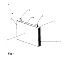
- FIG. 1 is a perspective view of a prismatic storage cell of prior art
- FIG. 2 is a perspective view of a prismatic storage cell with fastening mechanisms
- FIG. 3 is perspective exploded view of an intermediate sheet with fastening mechanism and the arrangement of several intermediate sheets in a cell module;
- FIG. 4 is a perspective view of a clamped cell module
- FIG. 5 is perspective view of an intermediate sheet with flag-like fastening mechanism and end-side flaring, and with head-side edgings;
- FIG. 6 is perspective view of an intermediate sheet with head-side edgings as supports in tensional direction for supporting the friction forces, or as variant for non-pressed cell modules;
- FIG. 7 is a perspective view of a cooling body and an exploded cooling body
- FIG. 8 illustrates a perspective view of a cooling body positioned to be assembled on the clamped cell module and the result of such assembly
- FIG. 9 a is a perspective view of a clamping member
- FIG. 9 b illustrates a perspective view of a first clamping member positioned to clamp the cooling body to the cell module and the result of such clamping
- FIG. 10 illustrates a cooling body partially clamped to the cell module and a fully clamped cooling body
- FIG. 11 is a perspective view of an assembled battery unit.
- FIG. 1 a prismatic storage cell 1 of prior art is shown.
- a prismatic storage cell 1 is generally accommodated in a prismatic cell casing 2 with two large surfaces 3 arranged parallel to each other and four narrow side surfaces 4 , which with their narrow length define the cell depth, or cell thickness.
- the two electrodes 5 of the storage cell 1 project from the side surface 4 a , specifically the head surface 4 a , to the top.
- FIG. 2 shows a prismatic cell casing 2 of a storage cell 1 with integrated fastening mechanism 6 that is, for example, available in form of an extruded part made of aluminum.
- the prismatic cell casings 2 are provided with at least one bottom-side fastening mechanism 6 as a device for fastening a cooling body to the coolant casing, specifically a fastening mechanism 6 that is established at the narrow side surface 4 b that forms the cell casing bottom 4 b directed to the bottom, parallel opposite to the head surface 4 a of the coolant casing.
- a fastening mechanism 6 As illustrated in FIG. 2 , as an exemplary fastening mechanism 6 , four half rivets 7 are illustrated.
- the cell stacks of a cell module 9 are extended by at least one intermediate sheet 8 that has at least one fastening mechanism 6 projecting at the bottom side of the cell module 9 .
- FIG. 3 shows such a cell module 9 in form of a cell stack where the prismatic cell casings 2 with their large surfaces 3 arranged parallel to each other are displaced one adjacent to the other in a stack.
- intermediate sheets 8 are inserted between the prismatic cell casings 2 so that in the cell stack of the prismatic cell casing 2 storage cells 1 and intermediate sheets 8 alternate arranged one next to the other.
- the fastening mechanism 6 corresponds to the contour of a half rivet 7 .
- FIG. 4 shows a clamped cell module 9 .
- the cell module 9 comprises a plurality of storage cells 1 with the prismatic cell casings 2 having their large surfaces 3 are arranged one above the other in a stack or adjacent to one another in a stack, and intermediate sheets 8 inserted between the prismatic cell casings 2 of the storage cells 1 .
- the prismatic cell casings 2 and the intermediate sheets 8 form the cell module 9 in the form of a cell stack where the cell casings 2 of the storage cells 1 and the intermediate sheets 8 are alternate arranged one above the other or one adjacent to the other.
- the cell module 9 is clamped using a clamping device, including as exemplary illustrated in FIG. 4 , two clamping plates 11 with three horizontally oriented, parallel distanced clamping bodies 11 a each situated on the faces 12 of the cell module 1 .
- the clamping plates 11 are designed wider than the large surfaces 3 of the cell casings 2 such that they project over the cell casings 2 on both sides in the horizontal direction as illustrated in FIG. 4 .
- the clamping bodies 11 a of the clamping plates 11 located on the opposite faces 12 of the cell module 9 are connected to each other by totally six clamping shafts 13 that run on both sides (three clamping shafts at one side) parallel to both longitudinal sides 14 of the cell module 9 .
- Both end regions 15 of the clamping shafts 13 are passed through holes in the clamping bodies 11 a , whereby both end regions 15 , as to the representation of FIG. 4 , are established as external threads that correspond to the internal threads of hexagonal nuts 16 as the clamping member 16 .
- both end regions 15 of the clamping shafts 13 placed on both sides parallel to the longitudinal sides 14 of the cell module 9 to the clamping members 16 the process of cell module clamping is performed, with, as to FIG. 4 , washers 17 placed between the clamping members 16 and the clamping bodies 11 a .
- the intermediate sheets 8 are force-closed fixed after cell module clamping between the storage cells 1 so that the fastening mechanisms 6 are capable to take tensional forces in direction of the cell height.
- intermediate sheets 8 with head-side edgings 18 are used instead as illustrated in FIG. 5 .
- the fastening mechanisms 6 of the intermediate sheets 8 are provided in form of flag-like sheet stripes 19 with end-side flaring 20 .
- the mutually oriented edgings 18 of the intermediate sheets 8 are situated on the head surfaces 4 a of the cell casings 2 , as shown in FIG. 6 .
- a intermediate sheet 8 with head-side edgings functions as support in tensional direction to support the friction forces, or as variant for unpressed cell modules, respectively.
- FIG. 7 shows the structure of a cooling body 21 for the battery unit.
- the cooling body 21 can comprise a wide multi channel flat tube 22 with collecting tubes 23 . Further, it has a plurality of through holes 24 . At the points of the through holes 24 either no channels of the multi channel flat tube 22 exist or the respective channels are not connected to the collecting tubes 23 .
- a common base plate 25 that simplifies mounting but also can have heat-insulating properties.
- a further configuration of the cooling body 21 is the design in form of plates such as known from plate heat exchangers.
- the plates do not comprise, however, two profiled half shells of sheet metal, but preferably comprise a profiled plate of sheet metal and a planar plate of sheet metal. For tightness reasons both plates are preferably brazed or welded to each other.
- the planar plate side is in thermal contact to the bottoms of the storage cells.
- Wide multi channel flat tubes 22 or plates do not exclude the use of a base plate 25 , for example for stability or thermal reasons.
- FIG. 8 represents the process of joining together a clamped cell module and a cooling body 21 .
- the cooling body 21 is designed such that the main direction of the coolant flow crosses the storage cells 1 of a cell module 9 , or is oriented in direction of the cell depth (cell thickness).
- the cooling body 21 is provided with through holes 24 dependent on the type of fastening mechanism 6 (half rivets, as to FIG. 8 ) so that the cooling body 21 can be brought into contact with the cell casing bottom surfaces 4 b of all cell casings 2 in order to effectively dissipate the heat loss developed in the storage cells 1 .
- Specific clamping members 26 fix the cooling body 21 to the cell module 9 , or press the cooling body 21 flatly to the cell casing bottoms 4 b , respectively, for uninterruptible heat conduction, whereby FIG. 9 a shows a single clamping member and, FIG. 9 b the mounting of a cooling body 21 to a cell module 9 using the first clamping member 26 .
- a clamping member 26 as to the exemplary embodiment shown in FIG. 9 b , is typically not wider than two cell depths and about as long as the width of a storage cell 1 .
- the clamping members 26 can also be established wider so that they can fix and press against the cooling body 21 several storage cells 1 or a whole cell module 9 at the same time (not illustrated).
- the height and cross-section of a clamping member 26 apart from its material properties, depend on the width and number of fastening mechanisms 6 per storage cell 1 , or per intermediate sheet 8 , respectively.
- the clamping member 26 is preferably provided with through holes 27 corresponding to the fastening mechanisms at the storage cell 1 /cell module 9 , the through holes 27 which as illustrated laterally change to a T-slot 28 .
- the clamping member 26 can be placed flat on the cooling body 21 , or the base plate 25 of the cooling body 21 , through the through holes 27 over the fastening mechanism 6 .
- the heads of the fastening mechanisms 6 come into the T-slot area 28 .
- the contact surface of the T-slot 28 is established as an inclined area (as inclined plane) (alternatively, also the contact surface of the head of the fastening mechanism 6 , or both surfaces)
- the clamping member 26 and the fastening means 6 , or the storage cells 1 or cell module 9 are pulled against each other.
- the cell casing bottom not shown in FIG. 9 b , see FIG. 8
- the cooling body 21 are pressed to each other so tight that their surfaces sufficiently contact each to ensure continuous heat conduction.
- easy and simultaneous fixing and clamping of the plate-shaped cooling body is performed using slide members that are captively premounted to the plate-shaped cooling body through guides.
- the guides are integrated at the lower side of the base plate 25 , the corresponding counterparts are provided at the clamping members 26 .
- FIG. 10 shows further mounting of the cooling body 21 to the cell module 9 using six clamping members 26 .
- the clamping members 26 are made of plastics and relaxation is expected due to the necessary surface pressure between the fastening mechanisms 6 and the clamping members 26
- the clamping members 26 in the region of the T-slots 28 may be provided with metallic backing plates or spring members. Additionally or alternatively, the clamping members 26 in the region of the T-slots 28 may be provided with metallic cores or inserts.
- the clamping members 26 are captively premounted to the base plate 25 over T-slots, such as dovetail guides or the like.
- FIG. 11 shows a completely assembled battery unit 29 for hybrid or electric vehicles, comprising a cell module 9 and a cooling device 21 .
Landscapes
- Engineering & Computer Science (AREA)
- Manufacturing & Machinery (AREA)
- Chemical & Material Sciences (AREA)
- Chemical Kinetics & Catalysis (AREA)
- Electrochemistry (AREA)
- General Chemical & Material Sciences (AREA)
- Secondary Cells (AREA)
- Battery Mounting, Suspending (AREA)
Abstract
Description
Claims (10)
Applications Claiming Priority (4)
| Application Number | Priority Date | Filing Date | Title |
|---|---|---|---|
| DE102009027465 | 2009-07-03 | ||
| DE102009027465.0 | 2009-07-03 | ||
| DE102010029872A DE102010029872A1 (en) | 2009-07-03 | 2010-06-09 | Battery assembly for hybrid or electric vehicles |
| DE102010029872.7 | 2010-06-09 |
Publications (2)
| Publication Number | Publication Date |
|---|---|
| US20110003187A1 US20110003187A1 (en) | 2011-01-06 |
| US8524387B2 true US8524387B2 (en) | 2013-09-03 |
Family
ID=43299295
Family Applications (1)
| Application Number | Title | Priority Date | Filing Date |
|---|---|---|---|
| US12/829,307 Expired - Fee Related US8524387B2 (en) | 2009-07-03 | 2010-07-01 | Battery unit for hybrid or electric vehicles |
Country Status (3)
| Country | Link |
|---|---|
| US (1) | US8524387B2 (en) |
| CN (1) | CN101944643B (en) |
| DE (1) | DE102010029872A1 (en) |
Cited By (5)
| Publication number | Priority date | Publication date | Assignee | Title |
|---|---|---|---|---|
| US20150357687A1 (en) * | 2014-06-04 | 2015-12-10 | Mahle International Gmbh | Temperature control device for controlling the temperature of a battery |
| US9450275B2 (en) | 2012-12-28 | 2016-09-20 | Johnson Controls Technology Company | Polymerized lithium ion battery cells and modules with overmolded heat sinks |
| US9853334B2 (en) | 2007-11-07 | 2017-12-26 | Enerdel, Inc. | Battery assembly with temperature control device |
| US10109829B2 (en) | 2015-11-05 | 2018-10-23 | Ford Global Technologies, Llc | Support assembly for traction battery |
| US10476045B2 (en) | 2016-02-22 | 2019-11-12 | Ford Global Technologies, Llc | Extruded battery case |
Families Citing this family (49)
| Publication number | Priority date | Publication date | Assignee | Title |
|---|---|---|---|---|
| US7531270B2 (en) * | 2006-10-13 | 2009-05-12 | Enerdel, Inc. | Battery pack with integral cooling and bussing devices |
| DE102010031462A1 (en) * | 2010-07-16 | 2012-01-19 | Sb Limotive Company Ltd. | Battery cell module, battery and motor vehicle |
| DE102011107075B4 (en) * | 2010-08-30 | 2019-11-28 | Samsung Sdi Co., Ltd. | battery module |
| DE102010046529A1 (en) * | 2010-09-24 | 2012-03-29 | Volkswagen Ag | Frame system for battery cells and battery module |
| WO2012052131A2 (en) * | 2010-10-14 | 2012-04-26 | Magna E-Car Systems Gmbh & Co Og | Rechargeable battery having a bending support and production method therefor |
| CA3053807A1 (en) | 2010-10-29 | 2012-05-03 | Dana Canada Corporation | Heat exchanger and battery unit structure for cooling thermally conductive batteries |
| KR101303426B1 (en) * | 2011-01-12 | 2013-09-05 | 로베르트 보쉬 게엠베하 | Battery module |
| EP2650960B1 (en) * | 2011-01-26 | 2020-01-01 | LG Chem, Ltd. | Cooling element having improved assembly productivity and battery modules including same |
| DE102011003535A1 (en) * | 2011-02-02 | 2012-08-02 | Behr Gmbh & Co. Kg | tensioning devices |
| AT511117B1 (en) * | 2011-03-09 | 2014-11-15 | Avl List Gmbh | ELECTRIC ENERGY STORAGE |
| CN107946689B (en) * | 2011-04-15 | 2021-01-22 | Cps科技控股有限公司 | Battery system with external thermal management system |
| AT511541A1 (en) * | 2011-05-16 | 2012-12-15 | Avl List Gmbh | RECHARGEABLE BATTERY |
| JP2012248339A (en) * | 2011-05-25 | 2012-12-13 | Sanyo Electric Co Ltd | Power unit for electric power and vehicle with power unit |
| DE102011077340A1 (en) * | 2011-06-10 | 2012-12-13 | Sb Limotive Company Ltd. | Battery module, battery with this battery module and motor vehicle with this battery |
| DE102011077349A1 (en) * | 2011-06-10 | 2012-12-13 | Sb Limotive Co., Ltd. | Battery and motor vehicle with this battery |
| DE102011077331A1 (en) * | 2011-06-10 | 2012-12-13 | Sb Limotive Company Ltd. | Battery module, battery with this battery module and motor vehicle with this battery |
| DE102011107007B4 (en) * | 2011-07-09 | 2026-05-07 | Volkswagen Aktiengesellschaft | Arrangement of a traction battery in a motor vehicle |
| DE102011080974B4 (en) * | 2011-08-16 | 2023-06-01 | Robert Bosch Gmbh | battery and motor vehicle |
| DE102011081537A1 (en) * | 2011-08-25 | 2013-02-28 | Sb Limotive Company Ltd. | Battery system with temperature control of at least one battery cell and motor vehicle |
| DE202012102969U1 (en) | 2011-09-21 | 2012-09-05 | Visteon Global Technologies, Inc. | Battery cooling arrangement |
| CN102437305A (en) * | 2011-12-16 | 2012-05-02 | 淄博国利新电源科技有限公司 | Three-dimensional ventilating battery partition plate |
| US8999547B2 (en) * | 2011-12-22 | 2015-04-07 | Samsung Sdi Co., Ltd. | Battery module |
| US9437903B2 (en) | 2012-01-31 | 2016-09-06 | Johnson Controls Technology Company | Method for cooling a lithium-ion battery pack |
| DE102012208239A1 (en) * | 2012-05-16 | 2013-11-21 | Robert Bosch Gmbh | battery assembly |
| US9287536B2 (en) | 2012-08-07 | 2016-03-15 | John E. Waters | Battery module construction |
| DE102012218162B4 (en) * | 2012-10-04 | 2023-12-14 | Bayerische Motorenwerke Aktiengesellschaft | Energy storage arrangement |
| DE102013200774A1 (en) | 2013-01-18 | 2014-07-24 | Robert Bosch Gmbh | Device for controlling temperature of battery module of battery system for e.g. electric vehicle, has chamber formed and filled with coolant such that device expands in region of contact surface with inner pressure rising in chamber |
| JP6114041B2 (en) * | 2013-01-21 | 2017-04-12 | 住友重機械工業株式会社 | Storage module and work machine equipped with storage module |
| US20140356652A1 (en) * | 2013-06-04 | 2014-12-04 | Ford Global Technologies, Llc | Battery thermal management system for electrified vehicle |
| DE102013011692A1 (en) * | 2013-07-12 | 2015-01-29 | Daimler Ag | Energy storage device with a tempering device, method for producing the energy storage device |
| DE102013112732B4 (en) * | 2013-11-19 | 2021-04-29 | Dr. Ing. H.C. F. Porsche Aktiengesellschaft | Motor vehicle battery for the purely electric drive of a motor vehicle |
| JP6172016B2 (en) * | 2014-03-26 | 2017-08-02 | 株式会社デンソー | Battery module and battery pack |
| US9887401B2 (en) * | 2015-08-21 | 2018-02-06 | The Boeing Company | Battery assembly, battery containment apparatus, and related methods of manufacture |
| DE102016009212B4 (en) * | 2016-08-01 | 2026-01-29 | Audi Ag | Battery module and battery |
| KR102167632B1 (en) * | 2016-09-19 | 2020-10-19 | 주식회사 엘지화학 | Battery pack and vehicle comprising the battery pack |
| DE102017200442A1 (en) * | 2017-01-12 | 2018-07-12 | Mahle International Gmbh | Akkumulatortemperieranordnung |
| US10446893B2 (en) * | 2017-01-23 | 2019-10-15 | Ford Global Technologies, Llc | Electrified vehicle battery packs with battery attachment features |
| CN110959224A (en) * | 2017-07-31 | 2020-04-03 | 松下知识产权经营株式会社 | Battery modules, battery packs, and combined battery packs |
| WO2019036002A2 (en) * | 2017-08-18 | 2019-02-21 | Hyliion Inc. | Battery pack optimization for thermal management |
| JP7027255B2 (en) * | 2018-05-31 | 2022-03-01 | 本田技研工業株式会社 | Battery pack |
| ES2745350B2 (en) * | 2018-08-28 | 2021-11-16 | Torres Martinez M | PRESSURIZED ELECTROCHEMICAL BATTERY AND MANUFACTURING PROCESS OF THE SAME |
| JP7151493B2 (en) * | 2019-01-15 | 2022-10-12 | トヨタ自動車株式会社 | battery device |
| DE102019215636A1 (en) * | 2019-10-11 | 2021-04-15 | Robert Bosch Gmbh | Battery module |
| DE102019130384A1 (en) | 2019-11-11 | 2021-05-12 | Audi Ag | Method for assembling a traction battery for an electrically powered vehicle |
| JP7298550B2 (en) * | 2020-06-02 | 2023-06-27 | トヨタ自動車株式会社 | power storage device |
| TR2021012320A1 (en) * | 2021-08-04 | 2023-01-23 | İzmi̇r Yüksek Teknoloji̇ Ensti̇tüsü Rektörlüğü | A HYBRID BATTERY PACK THERMAL MANAGEMENT SYSTEM |
| CN115602965A (en) * | 2022-10-21 | 2023-01-13 | 中国第一汽车股份有限公司(Cn) | A battery cooling structure, battery assembly, electric vehicle and design method |
| CN116093473B (en) * | 2023-04-10 | 2023-06-23 | 江苏智泰新能源科技有限公司 | Combined lithium ion battery energy storage system |
| TR2023014013A1 (en) * | 2023-10-30 | 2025-05-21 | Oyak Renault Otomobil Fabrikalari Anonim Sirketi | A MODULAR BATTERY CASE |
Citations (6)
| Publication number | Priority date | Publication date | Assignee | Title |
|---|---|---|---|---|
| US5419982A (en) * | 1993-12-06 | 1995-05-30 | Valence Technology, Inc. | Corner tab termination for flat-cell batteries |
| US6858344B2 (en) | 2001-07-19 | 2005-02-22 | Matsushita Electric Industrial Co., Ltd. | Prismatic battery having cooling structure and battery pack using the same |
| US20050170240A1 (en) | 2004-02-04 | 2005-08-04 | Daimlerchrysler Ag | Electrochemical energy store |
| DE102006010063A1 (en) | 2006-03-04 | 2007-09-06 | Bbp Kunststoffwerk Marbach Baier Gmbh | Battery cooling device for vehicle, has base housing with homogeneous receivers and closed and liquid-sealed cooling medium chamber with inlet and outlet for cooling liquid, where cooling device is formed by laser welding |
| DE102007063176A1 (en) | 2007-12-20 | 2008-09-11 | Daimler Ag | Battery, particularly for hybrid drive or fuel cell vehicle, has heat conducting plate for tempering battery, which has multiple single cells connected together, in parallel or serially |
| DE102008016936A1 (en) | 2007-04-05 | 2008-10-09 | Behr Gmbh & Co. Kg | Electrochemical energy storage unit |
Family Cites Families (1)
| Publication number | Priority date | Publication date | Assignee | Title |
|---|---|---|---|---|
| JP2001196103A (en) * | 2000-01-12 | 2001-07-19 | Matsushita Electric Ind Co Ltd | Battery cooling structure |
-
2010
- 2010-06-09 DE DE102010029872A patent/DE102010029872A1/en not_active Withdrawn
- 2010-07-01 US US12/829,307 patent/US8524387B2/en not_active Expired - Fee Related
- 2010-07-05 CN CN201010224829.1A patent/CN101944643B/en active Active
Patent Citations (6)
| Publication number | Priority date | Publication date | Assignee | Title |
|---|---|---|---|---|
| US5419982A (en) * | 1993-12-06 | 1995-05-30 | Valence Technology, Inc. | Corner tab termination for flat-cell batteries |
| US6858344B2 (en) | 2001-07-19 | 2005-02-22 | Matsushita Electric Industrial Co., Ltd. | Prismatic battery having cooling structure and battery pack using the same |
| US20050170240A1 (en) | 2004-02-04 | 2005-08-04 | Daimlerchrysler Ag | Electrochemical energy store |
| DE102006010063A1 (en) | 2006-03-04 | 2007-09-06 | Bbp Kunststoffwerk Marbach Baier Gmbh | Battery cooling device for vehicle, has base housing with homogeneous receivers and closed and liquid-sealed cooling medium chamber with inlet and outlet for cooling liquid, where cooling device is formed by laser welding |
| DE102008016936A1 (en) | 2007-04-05 | 2008-10-09 | Behr Gmbh & Co. Kg | Electrochemical energy storage unit |
| DE102007063176A1 (en) | 2007-12-20 | 2008-09-11 | Daimler Ag | Battery, particularly for hybrid drive or fuel cell vehicle, has heat conducting plate for tempering battery, which has multiple single cells connected together, in parallel or serially |
Cited By (5)
| Publication number | Priority date | Publication date | Assignee | Title |
|---|---|---|---|---|
| US9853334B2 (en) | 2007-11-07 | 2017-12-26 | Enerdel, Inc. | Battery assembly with temperature control device |
| US9450275B2 (en) | 2012-12-28 | 2016-09-20 | Johnson Controls Technology Company | Polymerized lithium ion battery cells and modules with overmolded heat sinks |
| US20150357687A1 (en) * | 2014-06-04 | 2015-12-10 | Mahle International Gmbh | Temperature control device for controlling the temperature of a battery |
| US10109829B2 (en) | 2015-11-05 | 2018-10-23 | Ford Global Technologies, Llc | Support assembly for traction battery |
| US10476045B2 (en) | 2016-02-22 | 2019-11-12 | Ford Global Technologies, Llc | Extruded battery case |
Also Published As
| Publication number | Publication date |
|---|---|
| CN101944643B (en) | 2015-02-18 |
| CN101944643A (en) | 2011-01-12 |
| US20110003187A1 (en) | 2011-01-06 |
| DE102010029872A1 (en) | 2011-01-05 |
Similar Documents
| Publication | Publication Date | Title |
|---|---|---|
| US8524387B2 (en) | Battery unit for hybrid or electric vehicles | |
| EP2065963B1 (en) | Battery system cooled via coolant | |
| CN102934277B (en) | Device for supplying power, having a cooling assembly | |
| CN104037373B (en) | Series of cells and there is the battery module of this series of cells | |
| JP5183172B2 (en) | Battery system | |
| KR101563405B1 (en) | Apparatus for contacting heat exchanger elements with battery modules of motor vehicle | |
| RU2496185C2 (en) | Thermostabilised module from electric batteries | |
| CN103650200B (en) | Electric supply installation | |
| US8409743B2 (en) | Battery system with battery cells arranged in array alignment | |
| US20120282506A1 (en) | Electrochemical energy store for vehicles and method for cooling or heating such an electrochemical store | |
| CN111430604B (en) | Battery pack for vehicle and vehicle with battery pack | |
| JP6073737B2 (en) | Power storage module | |
| US20120301771A1 (en) | Energy store device | |
| US20140106199A1 (en) | Energy storage apparatus having a temperature control device | |
| US20110189526A1 (en) | Energy storage unit | |
| US20190267686A1 (en) | Battery module | |
| US20140178722A1 (en) | Battery mounting and cooling system | |
| US20110267778A1 (en) | Apparatus for Supplying Voltage to a Motor Vehicle Having Optimized Heat Dissipation | |
| US20140087231A1 (en) | Energy storage apparatus | |
| US20170194680A1 (en) | Power Supply Module for a Voltage Supply Apparatus Arranged in a Vehicle | |
| CN109565003B (en) | Battery cell carrier and housing for a stacked assembly including a plurality of battery cell carriers | |
| KR101781923B1 (en) | Battery cooler for vehicle | |
| CN104900822A (en) | Energy storage enclosure | |
| CN214706144U (en) | Battery module clamping device and battery pack | |
| KR102210929B1 (en) | Heat exchanger for battery cooling |
Legal Events
| Date | Code | Title | Description |
|---|---|---|---|
| AS | Assignment |
Owner name: VISTEON GLOBAL TECHNOLOGIES, INC., MICHIGAN Free format text: ASSIGNMENT OF ASSIGNORS INTEREST;ASSIGNORS:GRAAF, MARC;KOSTER, STEPHAN, DR.;WIESCHOLLEK, FLORIAN;SIGNING DATES FROM 20100723 TO 20100802;REEL/FRAME:024865/0222 |
|
| AS | Assignment |
Owner name: MORGAN STANLEY SENIOR FUNDING, INC., AS AGENT, NEW YORK Free format text: SECURITY AGREEMENT (REVOLVER);ASSIGNORS:VISTEON CORPORATION;VC AVIATION SERVICES, LLC;VISTEON ELECTRONICS CORPORATION;AND OTHERS;REEL/FRAME:025238/0298 Effective date: 20101001 Owner name: MORGAN STANLEY SENIOR FUNDING, INC., AS AGENT, NEW YORK Free format text: SECURITY AGREEMENT;ASSIGNORS:VISTEON CORPORATION;VC AVIATION SERVICES, LLC;VISTEON ELECTRONICS CORPORATION;AND OTHERS;REEL/FRAME:025241/0317 Effective date: 20101007 Owner name: MORGAN STANLEY SENIOR FUNDING, INC., AS AGENT, NEW Free format text: SECURITY AGREEMENT;ASSIGNORS:VISTEON CORPORATION;VC AVIATION SERVICES, LLC;VISTEON ELECTRONICS CORPORATION;AND OTHERS;REEL/FRAME:025241/0317 Effective date: 20101007 Owner name: MORGAN STANLEY SENIOR FUNDING, INC., AS AGENT, NEW Free format text: SECURITY AGREEMENT (REVOLVER);ASSIGNORS:VISTEON CORPORATION;VC AVIATION SERVICES, LLC;VISTEON ELECTRONICS CORPORATION;AND OTHERS;REEL/FRAME:025238/0298 Effective date: 20101001 |
|
| AS | Assignment |
Owner name: VISTEON SYSTEMS, LLC, MICHIGAN Free format text: RELEASE BY SECURED PARTY AGAINST SECURITY INTEREST IN PATENTS ON REEL 025241 FRAME 0317;ASSIGNOR:MORGAN STANLEY SENIOR FUNDING, INC.;REEL/FRAME:026178/0412 Effective date: 20110406 Owner name: VISTEON INTERNATIONAL BUSINESS DEVELOPMENT, INC., MICHIGAN Free format text: RELEASE BY SECURED PARTY AGAINST SECURITY INTEREST IN PATENTS ON REEL 025241 FRAME 0317;ASSIGNOR:MORGAN STANLEY SENIOR FUNDING, INC.;REEL/FRAME:026178/0412 Effective date: 20110406 Owner name: VC AVIATION SERVICES, LLC, MICHIGAN Free format text: RELEASE BY SECURED PARTY AGAINST SECURITY INTEREST IN PATENTS ON REEL 025241 FRAME 0317;ASSIGNOR:MORGAN STANLEY SENIOR FUNDING, INC.;REEL/FRAME:026178/0412 Effective date: 20110406 Owner name: VISTEON CORPORATION, MICHIGAN Free format text: RELEASE BY SECURED PARTY AGAINST SECURITY INTEREST IN PATENTS ON REEL 025241 FRAME 0317;ASSIGNOR:MORGAN STANLEY SENIOR FUNDING, INC.;REEL/FRAME:026178/0412 Effective date: 20110406 Owner name: VISTEON INTERNATIONAL HOLDINGS, INC., MICHIGAN Free format text: RELEASE BY SECURED PARTY AGAINST SECURITY INTEREST IN PATENTS ON REEL 025241 FRAME 0317;ASSIGNOR:MORGAN STANLEY SENIOR FUNDING, INC.;REEL/FRAME:026178/0412 Effective date: 20110406 Owner name: VISTEON GLOBAL TECHNOLOGIES, INC., MICHIGAN Free format text: RELEASE BY SECURED PARTY AGAINST SECURITY INTEREST IN PATENTS ON REEL 025241 FRAME 0317;ASSIGNOR:MORGAN STANLEY SENIOR FUNDING, INC.;REEL/FRAME:026178/0412 Effective date: 20110406 Owner name: VISTEON INTERNATIONAL BUSINESS DEVELOPMENT, INC., Free format text: RELEASE BY SECURED PARTY AGAINST SECURITY INTEREST IN PATENTS ON REEL 025241 FRAME 0317;ASSIGNOR:MORGAN STANLEY SENIOR FUNDING, INC.;REEL/FRAME:026178/0412 Effective date: 20110406 Owner name: VISTEON EUROPEAN HOLDING, INC., MICHIGAN Free format text: RELEASE BY SECURED PARTY AGAINST SECURITY INTEREST IN PATENTS ON REEL 025241 FRAME 0317;ASSIGNOR:MORGAN STANLEY SENIOR FUNDING, INC.;REEL/FRAME:026178/0412 Effective date: 20110406 Owner name: VISTEON ELECTRONICS CORPORATION, MICHIGAN Free format text: RELEASE BY SECURED PARTY AGAINST SECURITY INTEREST IN PATENTS ON REEL 025241 FRAME 0317;ASSIGNOR:MORGAN STANLEY SENIOR FUNDING, INC.;REEL/FRAME:026178/0412 Effective date: 20110406 Owner name: VISTEON GLOBAL TREASURY, INC., MICHIGAN Free format text: RELEASE BY SECURED PARTY AGAINST SECURITY INTEREST IN PATENTS ON REEL 025241 FRAME 0317;ASSIGNOR:MORGAN STANLEY SENIOR FUNDING, INC.;REEL/FRAME:026178/0412 Effective date: 20110406 |
|
| FEPP | Fee payment procedure |
Free format text: PAYOR NUMBER ASSIGNED (ORIGINAL EVENT CODE: ASPN); ENTITY STATUS OF PATENT OWNER: LARGE ENTITY |
|
| AS | Assignment |
Owner name: HALLA VISTEON CLIMATE CONTROL CORPORATION, KOREA, Free format text: ASSIGNMENT OF ASSIGNORS INTEREST;ASSIGNOR:VISTEON GLOBAL TECHNOLOGIES, INC.;REEL/FRAME:030935/0958 Effective date: 20130726 |
|
| STCF | Information on status: patent grant |
Free format text: PATENTED CASE |
|
| AS | Assignment |
Owner name: VC AVIATION SERVICES, LLC, MICHIGAN Free format text: RELEASE OF SECURITY INTEREST IN INTELLECTUAL PROPERTY;ASSIGNOR:MORGAN STANLEY SENIOR FUNDING, INC.;REEL/FRAME:033107/0717 Effective date: 20140409 Owner name: VISTEON CORPORATION, MICHIGAN Free format text: RELEASE OF SECURITY INTEREST IN INTELLECTUAL PROPERTY;ASSIGNOR:MORGAN STANLEY SENIOR FUNDING, INC.;REEL/FRAME:033107/0717 Effective date: 20140409 Owner name: VISTEON GLOBAL TREASURY, INC., MICHIGAN Free format text: RELEASE OF SECURITY INTEREST IN INTELLECTUAL PROPERTY;ASSIGNOR:MORGAN STANLEY SENIOR FUNDING, INC.;REEL/FRAME:033107/0717 Effective date: 20140409 Owner name: VISTEON EUROPEAN HOLDINGS, INC., MICHIGAN Free format text: RELEASE OF SECURITY INTEREST IN INTELLECTUAL PROPERTY;ASSIGNOR:MORGAN STANLEY SENIOR FUNDING, INC.;REEL/FRAME:033107/0717 Effective date: 20140409 Owner name: VISTEON INTERNATIONAL BUSINESS DEVELOPMENT, INC., Free format text: RELEASE OF SECURITY INTEREST IN INTELLECTUAL PROPERTY;ASSIGNOR:MORGAN STANLEY SENIOR FUNDING, INC.;REEL/FRAME:033107/0717 Effective date: 20140409 Owner name: VISTEON SYSTEMS, LLC, MICHIGAN Free format text: RELEASE OF SECURITY INTEREST IN INTELLECTUAL PROPERTY;ASSIGNOR:MORGAN STANLEY SENIOR FUNDING, INC.;REEL/FRAME:033107/0717 Effective date: 20140409 Owner name: VISTEON ELECTRONICS CORPORATION, MICHIGAN Free format text: RELEASE OF SECURITY INTEREST IN INTELLECTUAL PROPERTY;ASSIGNOR:MORGAN STANLEY SENIOR FUNDING, INC.;REEL/FRAME:033107/0717 Effective date: 20140409 Owner name: VISTEON GLOBAL TECHNOLOGIES, INC., MICHIGAN Free format text: RELEASE OF SECURITY INTEREST IN INTELLECTUAL PROPERTY;ASSIGNOR:MORGAN STANLEY SENIOR FUNDING, INC.;REEL/FRAME:033107/0717 Effective date: 20140409 Owner name: VISTEON INTERNATIONAL HOLDINGS, INC., MICHIGAN Free format text: RELEASE OF SECURITY INTEREST IN INTELLECTUAL PROPERTY;ASSIGNOR:MORGAN STANLEY SENIOR FUNDING, INC.;REEL/FRAME:033107/0717 Effective date: 20140409 Owner name: VISTEON INTERNATIONAL BUSINESS DEVELOPMENT, INC., MICHIGAN Free format text: RELEASE OF SECURITY INTEREST IN INTELLECTUAL PROPERTY;ASSIGNOR:MORGAN STANLEY SENIOR FUNDING, INC.;REEL/FRAME:033107/0717 Effective date: 20140409 |
|
| AS | Assignment |
Owner name: HANON SYSTEMS, KOREA, REPUBLIC OF Free format text: CHANGE OF NAME;ASSIGNOR:HALLA VISTEON CLIMATE CONTROL CORPORATION;REEL/FRAME:037007/0103 Effective date: 20150728 |
|
| FPAY | Fee payment |
Year of fee payment: 4 |
|
| MAFP | Maintenance fee payment |
Free format text: PAYMENT OF MAINTENANCE FEE, 8TH YEAR, LARGE ENTITY (ORIGINAL EVENT CODE: M1552); ENTITY STATUS OF PATENT OWNER: LARGE ENTITY Year of fee payment: 8 |
|
| FEPP | Fee payment procedure |
Free format text: MAINTENANCE FEE REMINDER MAILED (ORIGINAL EVENT CODE: REM.); ENTITY STATUS OF PATENT OWNER: LARGE ENTITY |
|
| LAPS | Lapse for failure to pay maintenance fees |
Free format text: PATENT EXPIRED FOR FAILURE TO PAY MAINTENANCE FEES (ORIGINAL EVENT CODE: EXP.); ENTITY STATUS OF PATENT OWNER: LARGE ENTITY |
|
| STCH | Information on status: patent discontinuation |
Free format text: PATENT EXPIRED DUE TO NONPAYMENT OF MAINTENANCE FEES UNDER 37 CFR 1.362 |
|
| FP | Lapsed due to failure to pay maintenance fee |
Effective date: 20250903 |