US8520720B2 - Spread spectrum communication system, clear channel assessment device and related method - Google Patents
Spread spectrum communication system, clear channel assessment device and related method Download PDFInfo
- Publication number
- US8520720B2 US8520720B2 US13/158,450 US201113158450A US8520720B2 US 8520720 B2 US8520720 B2 US 8520720B2 US 201113158450 A US201113158450 A US 201113158450A US 8520720 B2 US8520720 B2 US 8520720B2
- Authority
- US
- United States
- Prior art keywords
- signal
- calculated value
- coupled
- spreading
- generate
- Prior art date
- Legal status (The legal status is an assumption and is not a legal conclusion. Google has not performed a legal analysis and makes no representation as to the accuracy of the status listed.)
- Active, expires
Links
- 238000001228 spectrum Methods 0.000 title claims abstract description 48
- 238000004891 communication Methods 0.000 title claims abstract description 40
- 238000000034 method Methods 0.000 title claims description 36
- 230000008569 process Effects 0.000 claims description 13
- 238000001914 filtration Methods 0.000 claims description 9
- 230000004044 response Effects 0.000 claims description 3
- 238000013461 design Methods 0.000 description 4
- 238000010586 diagram Methods 0.000 description 4
- 238000001514 detection method Methods 0.000 description 3
- 238000012545 processing Methods 0.000 description 2
- 230000004075 alteration Effects 0.000 description 1
- 238000012986 modification Methods 0.000 description 1
- 230000004048 modification Effects 0.000 description 1
- 230000008054 signal transmission Effects 0.000 description 1
- 230000007480 spreading Effects 0.000 description 1
Images


Classifications
-
- H—ELECTRICITY
- H04—ELECTRIC COMMUNICATION TECHNIQUE
- H04B—TRANSMISSION
- H04B1/00—Details of transmission systems, not covered by a single one of groups H04B3/00 - H04B13/00; Details of transmission systems not characterised by the medium used for transmission
- H04B1/69—Spread spectrum techniques
- H04B1/707—Spread spectrum techniques using direct sequence modulation
-
- H—ELECTRICITY
- H04—ELECTRIC COMMUNICATION TECHNIQUE
- H04B—TRANSMISSION
- H04B7/00—Radio transmission systems, i.e. using radiation field
- H04B7/02—Diversity systems; Multi-antenna system, i.e. transmission or reception using multiple antennas
- H04B7/04—Diversity systems; Multi-antenna system, i.e. transmission or reception using multiple antennas using two or more spaced independent antennas
- H04B7/08—Diversity systems; Multi-antenna system, i.e. transmission or reception using multiple antennas using two or more spaced independent antennas at the receiving station
- H04B7/0802—Diversity systems; Multi-antenna system, i.e. transmission or reception using multiple antennas using two or more spaced independent antennas at the receiving station using antenna selection
- H04B7/0805—Diversity systems; Multi-antenna system, i.e. transmission or reception using multiple antennas using two or more spaced independent antennas at the receiving station using antenna selection with single receiver and antenna switching
Definitions
- the present invention relates to a spread spectrum (SS) communication technique, and more particularly, to a spread spectrum communication system, a clear channel assessment (CCA) device utilizing a plurality of receiving paths for clear channel assessment, and a related method.
- SS spread spectrum
- CCA clear channel assessment
- Spread spectrum is a communication technique of spreading the spectrum of a transmitted signal into a frequency band having a wider bandwidth, and is commonly used in wireless communication.
- Spread spectrum technique can be more stringently divided into two categories: the first being that, after spread spectrum modulation is performed, the signal transmission bandwidth is much larger than the original signal bandwidth; the second being that a transmitting end will employ a unique symbol, which does not affect transmitted data, and a receiving terminal also has to utilize the unique symbol to decode the spread spectrum to acquire the actual data transmitted from the transmitting end.
- DSSS direct-sequence spread spectrum
- FHSS frequency-hopping spread spectrum
- Spread spectrum communication technique is immune to background noise, interference and self multi-path interference, and influence from electromagnetic interference (EMI) is also minimal. Therefore, through the use of the spread spectrum technique, code division multiple access (CDMA) communication can be realized, which allows more users to independently utilize wider bandwidths at the same time.
- CDMA code division multiple access
- a receiving end of a spread spectrum communication system utilizes a rake receiver to receive signal power via different wireless communication paths; however, the rake receiver has to start operation after finishing channel assessment, and is of little help for signal processing (e.g., packet detection) before channel assessment. Since packet assessment is the most significant part in signal reception, if packets cannot be detected correctly, subsequent signal detection and processing operations also cannot proceed properly.
- signal processing e.g., packet detection
- FIG. 1 is a diagram of a conventional spread spectrum communication system 100 .
- the spread spectrum communication system 100 includes an antenna 110 , a radio frequency demodulator 115 , an analog-to-digital converter (ADC) 120 , a digital finite impulse response (DFIR) filter, a clear channel assessment (CCA) device 140 , a switch circuit 150 , a rake receiver 160 and a symbol examination circuit 170 .
- the antenna 110 is for receiving a radio frequency (RF) signal S RF .
- the radio frequency demodulator 115 is coupled to the antenna 110 , and is for demodulating the radio frequency signal S RF into an analog baseband signal S BB .
- the ADC 120 is coupled to the radio frequency demodulator 115 , and is for converting the analog baseband signal S BB into a digital signal S dig .
- the DFIR filter 130 is coupled to the ADC 120 , and is for filtering the digital signal S dig to generate a filtered signal S f .
- the CCA device 140 is coupled to the DFIR filter 130 , and is for generating a channel assessment signal S cca according to signal characteristics of the filtered signal S f .
- the switch circuit 150 is coupled to the CCA device 140 , and is for referring to the channel assessment signal S cca to be selectively conducting (an “on” status) or non-conducting (an “off” status).
- the rake receiver 160 is coupled to the switch circuit 150 , and is for receiving the filtered signal S f to generate a received signal S r when the switching circuit 150 is conducting.
- the symbol examination circuit 170 is coupled to the rake receiver 160 , and is for performing symbol examination for the received signal S r .
- the CCA device 140 includes a de-spreading processor 141 , a switch 143 , a first power calculator 145 , a second power calculator 147 and a comparator 149 .
- the de-spreading processor 141 is for receiving the filtered signal S f and performing a de-spreading process for the filtered signal S f to generate a de-spreading signal S ds accordingly.
- the switch 143 is coupled to the de-spreading processor 141 , and refers to the de-spreading signal S ds to be selectively conducting or non-conducting.
- the first power calculator 145 is coupled to the switch 143 , and is for receiving the de-spreading signal S ds , and calculating the power of the de-spreading signal S ds to generate a first calculated value C 1 .
- the second power calculator 147 is for receiving the filtered signal S f , and calculating the power of the filtered signal S f to generate a second calculated value C 2 .
- the comparator 149 is coupled to the first power calculator 145 and the second power calculator 147 , and is for generating the channel assessment signal S cca according to the first calculated value C 1 and the second calculated value C 2 .
- the CCA device 140 can detect if there is a packet being transmitted by referring to signal characteristics of the filtered signal S f .
- a signal power after de-spreading e.g., the calculated value C 1
- the CCA device 140 determines that a packet is detected.
- the CCA device 140 will control the switch circuit 150 to be conducting via the channel assessment signal S cca , and activate the following rake receiver 160 and symbol examination circuit 170 .
- the rake receiver 160 can enhance signal detection quality; however, if the CCA device 140 cannot successfully detect a packet in time, the rake receiver 160 is unable to proceed to following operations.
- one of the objectives of the present invention is to provide a spread spectrum communication system, a clear channel assessment device utilizing a plurality of receiving paths for clear channel assessment, and related methods, in order to solve aforementioned problems encountered in the prior art.
- a spread spectrum system includes a first antenna, a second antenna, a first radio frequency demodulator, a second radio frequency demodulator, a first analog-to-digital converter (ADC), a second ADC, a first filter, a second filter, a clear channel assessment device and a selection device.
- the first antenna is for receiving a first radio frequency signal.
- the second antenna is for receiving a second radio frequency signal.
- the first radio frequency demodulator is coupled to the first antenna, and is for converting the first radio frequency signal into a first analog baseband signal.
- the second radio frequency demodulator is coupled to the second antenna, and is for converting the second radio frequency signal into a second analog baseband signal.
- the first ADC is coupled to the first radio frequency demodulator, and is for converting the first analog baseband signal into a first digital signal.
- the second ADC is coupled to the second radio frequency demodulator, and is for converting the second analog baseband signal into a second digital signal.
- the first filter is coupled to the first ADC, and is for filtering the first digital signal to generate a first filtered signal.
- the second filter is coupled to the second ADC, and is for filtering the second digital signal to generate a second filtered signal.
- the clear channel assessment device is coupled to the first filter and the second filter, and is for generating a channel assessment signal and a path selection signal according to signal characteristics of the first filtered signal and the second filtered signal.
- the selection device is coupled to the first filter, the second filter and the clear channel assessment device, and the selection device is for referring to at least one of the channel assessment signal and path selection signal to selectively output the first filtered signal, output the second filtered signal, or generate no signal output.
- a clear channel assessment device includes a first input terminal, a second input terminal, a first de-spreading device, a second de-spreading device, a first switch, a second switch, a first power calculator, a second power calculator, a third power calculator, a fourth power calculator and a channel assessment comparator.
- the first input terminal is for receiving a first input signal.
- the second input terminal is for receiving a second input signal.
- the first de-spreading device is coupled to the first input terminal, and is for performing a de-spreading process for the first input signal to generate a first de-spreading signal.
- the second de-spreading device is coupled to the second input terminal, and is for performing a de-spreading process for the second input signal to generate a second de-spreading signal.
- the first switch is coupled to the first de-spreading device, and is selectively conducting or non-conducting according to the first de-spreading signal.
- the second switch is coupled to the second de-spreading device, and is selectively conducting or non-conducting according to the second de-spreading signal.
- the first power calculator is coupled to the first switch, and is for receiving the first de-spreading signal transmitted by the first switch when the first switch is conducting, and calculating a first calculated value according to a signal power of the first de-spreading signal.
- the second power calculator is coupled to the second switch, and is for receiving the second de-spreading signal transmitted by the second switch when the second switch is conducting, and calculating a second calculated value according to a signal power of the second de-spreading signal.
- the third power calculator is coupled to the first filter, and is for calculating a third calculated value according to a signal power of the first filtered signal.
- the fourth power calculator is coupled to the second filter, and is for calculating a fourth calculated value according to a signal power of the second filtered signal.
- the channel assessment comparator is coupled to the first power calculator, the second power calculator, the third power calculator and the fourth power calculator, and the channel assessment comparator is for generating the channel assessment signal according to the first calculated value, the second calculated signal, the third calculated signal and the fourth calculated signal.
- a spread spectrum communication method includes: deriving a first signal from a first antenna via a first path; deriving a second signal from a second antenna via a second path; generating a channel assessment signal and a path selection signal according to signal characteristics of the first signal and the second signal; and referring to at least one of the channel assessment signal and path selection signal to selectively output one of the first filtered signal, the second filtered signal, or generate no signal output.
- FIG. 1 is a diagram of a conventional spread spectrum communication system.
- FIG. 2 is a diagram of a spread spectrum system according to an embodiment of the present invention.
- FIG. 3 is an exemplary flow chart of a spread spectrum communication method according to an embodiment of the present invention.
- the first antenna 202 receives a first radio frequency signal S RF1 .
- the first radio frequency demodulator 203 is coupled to the first antenna 202 , and is for converting the first radio frequency signal S RF1 into a first analog baseband signal S BB1 .
- the first analog-to-digital converter (ADC) 206 is coupled to the first radio frequency demodulator 203 , and is for converting the first analog baseband signal S BB1 into a first digital signal S dig1 .
- the second antenna 204 receives a second radio frequency signal S RF2 .
- the second radio frequency demodulator 205 is coupled to the second antenna 204 , and is for converting the second radio frequency signal S RF2 into a second analog baseband signal S BB2 .
- the second ADC 208 is coupled to the second radio frequency demodulator 205 , and is for converting the second analog baseband signal S BB2 into a second digital signal S dig2 .
- the first filter 210 is coupled to the first ADC 206 , and is for filtering the first digital signal S dig1 to generate a first filtered signal S f1 .
- the second filter 212 is coupled to the second ADC 208 , and is for filtering the second digital signal S dig2 to generate a second filtered signal S f2 .
- the clear channel assessment (CCA) device 220 is coupled to the first filter 210 and the second filter 212 , and is for generating a channel assessment signal S cca ′ and a path selection signal S path according to signal characteristics of the first filtered signal S f1 and the second filtered signal S f2 .
- CCA clear channel assessment
- the selection device 260 is coupled to the first filter 210 , the second filter 212 and the CCA device 220 , and the selection device 260 is for referring to at least one of the channel assessment signal S cca ′ and path selection signal S path to selectively output the first filtered signal S f1 , output the second filtered signal S f2 , or generate no signal output.
- the first filter 210 and the second filter 212 may both be realized by digital finite impulse response (DFIR) filters; however, this is not supposed to be a limitation to the present invention.
- the first filter 210 and the second filter 212 may also be implemented with other kinds of filters according to different design requirements in other embodiments.
- the CCA device 220 has a first input terminal 310 and a second input terminal 320 used for receiving a first input signal and a second input signal, respectively.
- the first input terminal 310 is coupled to the first filter 210
- the second input terminal 320 is coupled to the second filter 212 .
- the aforementioned first input signal is the first filtered signal S f1 generated by the first filter 210
- the aforementioned second input signal is the second filtered signal S f2 generated by the second filter 212 .
- This example is for illustrative purposes only, and is not supposed to be a limitation to the present invention. Any communication system utilizing the CCA device 200 shown in FIG. 2 obeys the spirit of the present invention and accordingly falls within the scope of the present invention.
- the first de-spreading device 222 is coupled to the first filter 210 via the first terminal 310 , and is for performing a de-spreading process for the first filtered signal S f1 to thereby generate a first de-spreading signal S ds1 .
- the second de-spreading device 224 is coupled to the second filter 212 via the second terminal 320 , and is for performing a de-spreading process for the second filtered signal S f2 to thereby generate a second de-spreading signal S ds2 .
- the first switch 226 is coupled to the first de-spreading device 222 , and is selectively conducting (an “on” status) or non-conducting (an “off” status) according to the first de-spreading signal S ds1 .
- the second switch 228 is coupled to the second de-spreading device 224 , and is selectively conducting or non-conducting according to the second de-spreading signal S ds2 .
- a first power calculator 230 is coupled to the first switch 226 , and is for receiving the first de-spreading signal S ds1 transmitted via the first switch 226 when the first switch 226 is conducting, and calculating a first calculated value C cal1 according to a signal power of the first de-spreading signal S ds1 .
- a second power calculator 232 is coupled to the second switch 228 , and is for receiving the second de-spreading signal S ds2 transmitted via the second switch 228 when the second switch 228 is conducting, and calculating a second calculated value C cal2 according to a signal power of the second de-spreading signal S ds2 .
- a third power calculator 234 is coupled to the first filter 210 , and is for calculating a third calculated value C cal3 according to a signal power of the first filtered signal S f1 .
- a fourth power calculator 236 is coupled to the second filter 212 , and is for calculating a fourth calculated value C cal4 according to a signal power of the second filtered signal S f2 .
- a path power comparator 238 is coupled to the first power calculator 230 , the second power calculator 232 , the third power calculator 234 and the fourth power calculator 236 , and is for generating the channel assessment signal S cca ′ according to the first calculated value C cal1 , the second calculated signal C cal2 , the third calculated signal C cal3 and the fourth calculated signal C cal4 .
- a channel assessment comparator 240 includes (but is not limited to) a first adder 242 , a second adder 244 and a comparator 246 .
- the first adder 242 is coupled to the first power calculator 230 and the second power calculator 232 , and is for summing up the first calculated value C cal1 and the second calculated value C cal2 to generate a fifth calculated value C cal5 .
- the second adder 244 is coupled to the third power calculator 234 and the fourth power calculator 236 , and is for summing up the third calculated value C cal3 and the fourth calculated value C cal4 to generate a sixth calculated value C cal6 .
- the comparator 246 is coupled to the first adder 242 and the second adder 244 , and is for comparing the fifth calculated value C cal5 and the sixth calculated value C cal6 to generate the channel assessment signal S cca ′.
- the selection device 260 includes (but is not limited to) a path selector 262 and a switch circuit 264 .
- the path selector 262 is coupled to the first filter 210 , the second filter 212 and the CCA device 220 , and is for referring to the path selection signal S path to selectively output the first filtered signal S f1 or the second filtered signal S f2 .
- the switch circuit 264 is coupled to the path selector 262 , and is selectively conducting or non-conducting according to the channel assessment signal S cca ′.
- the path selector 262 may be implemented by a multiplexer; however, this is not supposed to be a limitation to the present invention.
- any device capable of providing signal selection functionality may be utilized to act as the path selector 262 , and these kinds of variation in design also fall within the scope of the present invention.
- the switch circuit 264 is coupled to an output terminal of the path selector 262 ; however, this is also not a limitation to the present invention.
- the selection device 260 can also be composed of two switch circuits and a path selector, where those switch circuits are coupled to different input terminals of the path selector. This kind of variation in design also falls within the scope of the present invention.
- the spread spectrum communication system 200 further includes a rake receiver 270 and a symbol examination circuit 280 .
- the rake receiver 270 is coupled to the switch circuit 264 , and is for receiving the first filtered signal S f1 or the second filtered signal S f2 via the path chosen by the selection device 260 to generate a received signal S rec .
- the symbol examination circuit 280 is coupled to the rake receiver 270 , and is for performing a symbol examination for the received signal S rec .
- the spread spectrum communication system 200 utilizes two different signal receiving paths to receive signals, and performs channel assessment and path selection according to signal powers received via two different paths; however, this example is only for illustrative purposes and is not supposed to be a limitation to the present invention. Utilizing a plurality of paths (i.e., more than two different paths) to receive signals and then performing channel assessment or path selection also falls within the scope of the present invention.
- the selection device 260 will output different outcomes according to magnitudes of the first calculated value C cal1 , the second calculated value C cal2 , the third calculated value C cal3 , the fourth calculated value C cal4 , the fifth calculated value C cal5 and the sixth calculated value C cal6 : if the first calculated value C cal1 is larger than the second calculated value C cal2 , a path selection signal S path1 generated by the path power comparator 238 will control the path selector 262 to output the first filtered signal S f1 ; if the first calculated value C cal1 is smaller than the second calculated value C cal2 , a path selection signal S path2 generated by the path power comparator 238 will control the path selector 262 to output the second filtered signal S f2 ; if the fifth calculated value C cal5 is larger than a specific ratio of
- the CCA device 220 will generate the channel assessment signal and the path selection signal simultaneously/concurrently; however, this is for illustrative purposes only and is not supposed to be a limitation to the present invention. In other embodiments, the CCA device 220 may only generate the channel assessment signal or only generate the path selection signal/path comparison result; these kinds of variation in design also fall within the scope of the present invention.
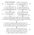
- FIG. 3 is an exemplary flow chart of a spread spectrum communication method according to an embodiment of the present invention. Please note that if the result is substantially the same, the steps are not required to be executed in the exact order shown in FIG. 3 . In addition, the steps in FIG. 3 are not required to be executed sequentially, i.e., other steps can be inserted in between. The steps are detailed as follows:
- Step 402 Utilize a first antenna to receive a first radio frequency signal.
- Step 404 Utilize a second antenna to receive a second radio frequency signal.
- Step 406 Convert the first radio frequency signal into a first analog baseband signal.
- Step 408 Convert the second radio frequency signal into a second analog baseband signal.
- Step 410 Convert the first analog baseband signal into a first digital signal.
- Step 412 Convert the second analog baseband signal into a second digital signal.
- Step 414 Filter the first digital signal to generate a first filtered signal.
- Step 416 Filter the second digital signal to generate a second filtered signal.
- Step 418 Generate a channel assessment signal and a path selection signal according to signal characteristics of the first digital signal and the second digital signal.
- Step 420 Refer to at least one of the channel assessment signal and the path selection signal to selectively output the first filtered signal, output the second filtered signal, or generate no signal output.
- a first signal and a second signal are derived from a first antenna and a second antenna via a first path and a second path, respectively (steps 402 - 416 ).
- the first radio frequency signal S RF1 is received from the first antenna 202 , and then the first radio frequency signal S RF1 goes through the first radio frequency demodulator 203 , the first ADC 206 and the first filter 210 and is converted into the first filtered signal S f1 .
- the first path is a signal path in which the first radio frequency demodulator 203 , the first ADC 206 and the first filter 210 are disposed, and the first signal is the first filtered signal S f1 .
- the second path is a signal path in which the second radio frequency demodulator 205 , the second ADC 208 and the second filter 212 are disposed, and the second signal is the second filtered signal S f2 .
- the path power comparator 238 is utilized to generate the path selection signal S path (step 418 ).
- an output signal is generated by referring to the path selection signal (i.e., the path selection signal S path ) to selectively output the first signal (i.e., the first filtered signal S f1 ) or the second signal (i.e., the second filtered signal S f2 ), and the output signal is selectively outputted by referring to the channel assessment signal.
- the path selection signal i.e., the path selection signal S path
- the first signal i.e., the first filtered signal S f1
- the second signal i.e., the second filtered signal S f2
- the present invention provides a spread spectrum communication system, a clear channel assessment apparatus and related method.
- the spread spectrum system and the clear channel assessment apparatus of the present invention receive signals via a plurality of receiving paths and a plurality of input terminals, calculate powers of the received signals before and after de-spreading, and then perform channel assessment as well as path selection according to calculation results to thereby provide more reliable examination results.
- the present invention can provide stable receiving performance when the signal energy received by the receiving end of the system/apparatus is very weak, and therefore can choose a better receiving path for signal reception.
Landscapes
- Engineering & Computer Science (AREA)
- Computer Networks & Wireless Communication (AREA)
- Signal Processing (AREA)
- Mobile Radio Communication Systems (AREA)
- Circuits Of Receivers In General (AREA)
Abstract
Description
Claims (16)
Applications Claiming Priority (3)
| Application Number | Priority Date | Filing Date | Title |
|---|---|---|---|
| TW99119726A | 2010-06-17 | ||
| TW099119726 | 2010-06-17 | ||
| TW099119726A TWI437829B (en) | 2010-06-17 | 2010-06-17 | Spread spectrum communication system, clear channel assessment device and related method |
Publications (2)
| Publication Number | Publication Date |
|---|---|
| US20110310934A1 US20110310934A1 (en) | 2011-12-22 |
| US8520720B2 true US8520720B2 (en) | 2013-08-27 |
Family
ID=45328638
Family Applications (1)
| Application Number | Title | Priority Date | Filing Date |
|---|---|---|---|
| US13/158,450 Active 2032-04-24 US8520720B2 (en) | 2010-06-17 | 2011-06-12 | Spread spectrum communication system, clear channel assessment device and related method |
Country Status (2)
| Country | Link |
|---|---|
| US (1) | US8520720B2 (en) |
| TW (1) | TWI437829B (en) |
Citations (2)
| Publication number | Priority date | Publication date | Assignee | Title |
|---|---|---|---|---|
| US20030007473A1 (en) * | 1999-10-21 | 2003-01-09 | Jon Strong | Method and apparatus for integrating wireless communication and asset location |
| US20050047384A1 (en) * | 2003-08-27 | 2005-03-03 | Wavion Ltd. | WLAN capacity enhancement using SDM |
-
2010
- 2010-06-17 TW TW099119726A patent/TWI437829B/en active
-
2011
- 2011-06-12 US US13/158,450 patent/US8520720B2/en active Active
Patent Citations (2)
| Publication number | Priority date | Publication date | Assignee | Title |
|---|---|---|---|---|
| US20030007473A1 (en) * | 1999-10-21 | 2003-01-09 | Jon Strong | Method and apparatus for integrating wireless communication and asset location |
| US20050047384A1 (en) * | 2003-08-27 | 2005-03-03 | Wavion Ltd. | WLAN capacity enhancement using SDM |
Also Published As
| Publication number | Publication date |
|---|---|
| US20110310934A1 (en) | 2011-12-22 |
| TWI437829B (en) | 2014-05-11 |
| TW201201527A (en) | 2012-01-01 |
Similar Documents
| Publication | Publication Date | Title |
|---|---|---|
| US7106816B2 (en) | Supporting multiple wireless protocols in a wireless device | |
| JP3437524B2 (en) | Wireless communication device and wireless communication method | |
| JP2003520463A (en) | System and method for demodulating a turbo-coded signal by pilot-assisted coherent decoding | |
| JP2002064467A (en) | Method and device for cancelling multiple access interference in code division multiple access(cdma) communication system | |
| US8050639B2 (en) | Multi-antenna communication apparatus | |
| US6351462B1 (en) | CDMA receiving apparatus and method therefor | |
| EP1124346A1 (en) | Method and apparatus for radio reception | |
| US7003022B2 (en) | Matched filter and receiver for mobile radio communication system | |
| US20160329949A1 (en) | Apparatus and methods for scalable receivers | |
| GB2411546A (en) | Interference cancellation in CDMA system | |
| US8750817B2 (en) | Controlling filter bandwidth based on blocking signals | |
| JP2002520942A (en) | Improved CDMA receiver and method of operation thereof | |
| KR20010102190A (en) | Multibit spread spectrum signalling | |
| KR102918419B1 (en) | A nfc device, a method of operating the nfc device and a communication system including the nfc device | |
| US7327994B2 (en) | Architecture for multiple-antenna systems | |
| US9172413B2 (en) | Method and apparatus for performing wireless communications with aid of successive data processing in multiple iterations | |
| TW201203876A (en) | A radio receiver in a wireless communication system | |
| US6553058B1 (en) | Multi-user parallel interface canceler apparatus | |
| US8520720B2 (en) | Spread spectrum communication system, clear channel assessment device and related method | |
| US6263012B1 (en) | Receiver apparatus for CDMA communication system | |
| CN114531173B (en) | Multi-antenna frequency division duplex mode terminal receiving sensitivity optimization method and device and terminal equipment | |
| CN102299726B (en) | Spread spectrum communication system, idle channel estimating device and relevant method | |
| JP2001339455A (en) | Receiving device and wireless communication device | |
| US7573934B2 (en) | Spread spectrum rake receiver | |
| JP2001024554A (en) | Interference canceller for CDMA receiver |
Legal Events
| Date | Code | Title | Description |
|---|---|---|---|
| AS | Assignment |
Owner name: REALTEK SEMICONDUCTOR CORP., TAIWAN Free format text: ASSIGNMENT OF ASSIGNORS INTEREST;ASSIGNORS:LIN, YU-NAN;CHANG, YIN-SHAO;REEL/FRAME:026430/0364 Effective date: 20110608 |
|
| STCF | Information on status: patent grant |
Free format text: PATENTED CASE |
|
| FPAY | Fee payment |
Year of fee payment: 4 |
|
| MAFP | Maintenance fee payment |
Free format text: PAYMENT OF MAINTENANCE FEE, 8TH YEAR, LARGE ENTITY (ORIGINAL EVENT CODE: M1552); ENTITY STATUS OF PATENT OWNER: LARGE ENTITY Year of fee payment: 8 |
|
| MAFP | Maintenance fee payment |
Free format text: PAYMENT OF MAINTENANCE FEE, 12TH YEAR, LARGE ENTITY (ORIGINAL EVENT CODE: M1553); ENTITY STATUS OF PATENT OWNER: LARGE ENTITY Year of fee payment: 12 |