US8515644B2 - Method and device for controlling the speed of a motor vehicle - Google Patents
Method and device for controlling the speed of a motor vehicle Download PDFInfo
- Publication number
- US8515644B2 US8515644B2 US10/797,680 US79768004A US8515644B2 US 8515644 B2 US8515644 B2 US 8515644B2 US 79768004 A US79768004 A US 79768004A US 8515644 B2 US8515644 B2 US 8515644B2
- Authority
- US
- United States
- Prior art keywords
- vehicle
- time gap
- speed control
- preceding vehicle
- distance
- Prior art date
- Legal status (The legal status is an assumption and is not a legal conclusion. Google has not performed a legal analysis and makes no representation as to the accuracy of the status listed.)
- Active, expires
Links
- 238000000034 method Methods 0.000 title claims abstract description 8
- 230000001133 acceleration Effects 0.000 claims description 6
- 230000003213 activating effect Effects 0.000 claims 2
- 230000003044 adaptive effect Effects 0.000 description 6
- 230000006870 function Effects 0.000 description 5
- 230000006399 behavior Effects 0.000 description 4
- 238000002485 combustion reaction Methods 0.000 description 2
- 239000000446 fuel Substances 0.000 description 2
- 230000001419 dependent effect Effects 0.000 description 1
- 238000010586 diagram Methods 0.000 description 1
Images

Classifications
-
- B—PERFORMING OPERATIONS; TRANSPORTING
- B60—VEHICLES IN GENERAL
- B60W—CONJOINT CONTROL OF VEHICLE SUB-UNITS OF DIFFERENT TYPE OR DIFFERENT FUNCTION; CONTROL SYSTEMS SPECIALLY ADAPTED FOR HYBRID VEHICLES; ROAD VEHICLE DRIVE CONTROL SYSTEMS FOR PURPOSES NOT RELATED TO THE CONTROL OF A PARTICULAR SUB-UNIT
- B60W30/00—Purposes of road vehicle drive control systems not related to the control of a particular sub-unit, e.g. of systems using conjoint control of vehicle sub-units
- B60W30/14—Adaptive cruise control
- B60W30/16—Control of distance between vehicles, e.g. keeping a distance to preceding vehicle
-
- B—PERFORMING OPERATIONS; TRANSPORTING
- B60—VEHICLES IN GENERAL
- B60W—CONJOINT CONTROL OF VEHICLE SUB-UNITS OF DIFFERENT TYPE OR DIFFERENT FUNCTION; CONTROL SYSTEMS SPECIALLY ADAPTED FOR HYBRID VEHICLES; ROAD VEHICLE DRIVE CONTROL SYSTEMS FOR PURPOSES NOT RELATED TO THE CONTROL OF A PARTICULAR SUB-UNIT
- B60W2554/00—Input parameters relating to objects
- B60W2554/40—Dynamic objects, e.g. animals, windblown objects
- B60W2554/404—Characteristics
- B60W2554/4041—Position
-
- B—PERFORMING OPERATIONS; TRANSPORTING
- B60—VEHICLES IN GENERAL
- B60W—CONJOINT CONTROL OF VEHICLE SUB-UNITS OF DIFFERENT TYPE OR DIFFERENT FUNCTION; CONTROL SYSTEMS SPECIALLY ADAPTED FOR HYBRID VEHICLES; ROAD VEHICLE DRIVE CONTROL SYSTEMS FOR PURPOSES NOT RELATED TO THE CONTROL OF A PARTICULAR SUB-UNIT
- B60W2710/00—Output or target parameters relating to a particular sub-units
- B60W2710/06—Combustion engines, Gas turbines
- B60W2710/0605—Throttle position
-
- B—PERFORMING OPERATIONS; TRANSPORTING
- B60—VEHICLES IN GENERAL
- B60W—CONJOINT CONTROL OF VEHICLE SUB-UNITS OF DIFFERENT TYPE OR DIFFERENT FUNCTION; CONTROL SYSTEMS SPECIALLY ADAPTED FOR HYBRID VEHICLES; ROAD VEHICLE DRIVE CONTROL SYSTEMS FOR PURPOSES NOT RELATED TO THE CONTROL OF A PARTICULAR SUB-UNIT
- B60W2710/00—Output or target parameters relating to a particular sub-units
- B60W2710/06—Combustion engines, Gas turbines
- B60W2710/0616—Position of fuel or air injector
Definitions
- the present invention relates to a method and a device for controlling the speed of a motor vehicle, in which the speed functions in terms of a constant distance control in the case that at least one preceding vehicle is detected by a radar sensor, or the speed control functions in terms of a constant speed control in the case that no preceding vehicle is detected by a radar sensor, the distance to the preceding vehicle being able to be set by the driver in the form of a time gap.
- a change in the time gap by the driver causes the longitudinal dynamics of the speed control to change.
- An adaptive speed control that emits a radar beam and detects a preceding vehicle based on the reflected and received partial waves is known from the publication “Adaptive Cruise Control System Aspects and Development Trends” by Winner, Witte, Uhler and Lichtenberg, published at the SAE International Congress & Exposition, Detroit, Feb. 26-29, 1996. If this adaptive speed control detects a preceding vehicle, the speed of the vehicle is controlled in terms of a constant distance control and the preceding vehicle is followed. If the radar sensor detects that there is no preceding vehicle, the speed control regulates the speed of the vehicle in terms of constant speed control to a speed input set by the driver. It is also described that the distance of the vehicle from the preceding vehicle is able to be set in the form of a time gap. In this context, the time gap represents the time period that the driver's own vehicle requires to cover the intermediate vehicle distance. This results in a speed-dependent distance based on the natural driving behavior of a human driver.
- the core of the present invention is to change the driving behavior of the speed control as a function of the time gap setting.
- Drivers who prefer a sporty driving style select a shorter time gap compared to drivers who prefer driving comfortably and in a safety-conscious manner and select greater time gaps.
- Drivers who prefer driving in a sporty manner and accordingly select a shorter time gap also prefer more dynamic driving behavior for the speed control.
- the adjustment of the longitudinal dynamics of the vehicle as a function of the selected time gap allows the driver to select a driving style in a simple and traceable manner that would correspond with the driver's own driving style without distance control.
- a different driving program is selected by selecting and changing the time gap.
- the vehicle is also capable of accelerating or decelerating more quickly given a small time gap distance than in the case of greater time gaps.
- the deceleration devices of the vehicle are first activated at a shorter distance from the preceding vehicle. This advantage achieves a more dynamic driving style, provided that the driver selected a shorter time gap that corresponds with the sporty driver desire.
- a realization of the method of the present invention in the form of a control element provided for a control unit of an adaptive distance or speed control of a motor vehicle is of particular importance.
- a program is stored on the control element, is executable on a computer, in particular on a microprocessor or signal processor, and is suitable for carrying out the method of the present invention. Therefore, in this case, the present invention is realized by a program stored on the control element so that this control element provided with the program represents the present invention in the same manner as the method which is suitably carried out by the program.
- an electric storage medium e.g. a read only memory, may be used as the control element.
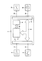
- the FIGURE shows a block diagram of an exemplary embodiment of the device of the present invention.
- the FIGURE shows a speed control device 1 , which has an input circuit 2 among other things.
- Input circuit 2 supplies input signals to speed control device 1 .
- object data 4 which are provided by a send and receive device for radar beam 3 , are supplied to input circuit 2 .
- the send and receive device for radar beam 3 sends radar signals that are reflected by objects at the edge of the roadway and by preceding vehicles.
- the reflected and received radar partial waves are evaluated in send and receive device 3 .
- At least the distance of detected objects, the relative speed of the detected objects, as well as the azimuth angle of the detected objects are supplied as object data 4 to input circuit 2 by send and receive device 3 .
- operating signals 6 which are generated by an operating device 5 , are supplied to input circuit 2 .
- Operating device 5 includes operating and control devices that the driver of the motor vehicle operates to activate the adaptive speed control as well as to select its functional settings. Operating element 5 allows the driver among other things to define a time gap that corresponds with the distance at which the driver's own vehicle is to follow behind a preceding vehicle.
- the signals received via input circuit 2 are supplied via a data exchange device 8 to a computing device 7 .
- Computing device 7 uses the input data to ascertain output signals that are relayed via data exchange device 8 to output circuit 11 .
- speed control device 1 has a storage device 9 , which is able to communicate with the computing device via a data exchange system 10 .
- data exchange device 8 may also be provided for data exchange device 8 as well as data exchange device 10 to be configured as a single data exchange system to which all components are connected.
- Different driving programs that may be transmitted via data exchange device 10 to computing device 7 depending on the selection of the time gap via operating element 5 are advantageously stored in storage device 9 .
- a change in the time gap via operating device 5 allows computing device 7 , which determines control signals for acceleration and deceleration devices 12 , 14 of the vehicle from the input signals, to accept a suitable driving program from memory 9 .
- the selected driving program corresponds with a longitudinal dynamics characteristic that corresponds with the selected time gap. If the driver desires a sporty, dynamic driving behavior, he selects a short time gap via operating device 5 , and a driving program that allows, for example, greater acceleration and deceleration values by the speed control than in the case of time gaps for a greater distance is accepted in computing device 7 from memory 9 .
- the deceleration devices of the vehicle are first activated at a shorter distance from the preceding vehicle than in the case of a comfortable and safety-conscious driving program corresponding to a greater time gap.
- the control signals determined as a function of supplied object data 4 and the selected driving program are sent via data exchange device 8 to an output circuit 11 , which sends an acceleration or a torque request 13 to a power-determining control element of an internal combustion engine 12 .
- Power-determining control element 12 may be configured, for example, as an electrically actuated throttle valve or as a fuel metering device in the form of a fuel injector for an internal combustion engine.
- Output circuit 10 also sends a deceleration signal 15 to deceleration devices 14 of the vehicle for the case that the vehicle must decrease its own speed. Deceleration devices 14 of the vehicle are advantageously configured as electrically actuatable breaking systems.
- the described device allows the driver to change the driving dynamics of speed control 1 via an easily manipulatable operating element 5 so that driver's driving desire is satisfied.
- the driver has access to a transparent operating concept for adaptive speed and distance control that is easily adaptable to the driver's wishes. This results in an easy to operate system, thereby increasing the transparency of the controller as well as the acceptance by the driver.
Landscapes
- Engineering & Computer Science (AREA)
- Automation & Control Theory (AREA)
- Transportation (AREA)
- Mechanical Engineering (AREA)
- Control Of Driving Devices And Active Controlling Of Vehicle (AREA)
- Controls For Constant Speed Travelling (AREA)
- Traffic Control Systems (AREA)
- Control Of Vehicle Engines Or Engines For Specific Uses (AREA)
Abstract
Description
Claims (3)
Applications Claiming Priority (3)
| Application Number | Priority Date | Filing Date | Title |
|---|---|---|---|
| DE10310720A DE10310720A1 (en) | 2003-03-10 | 2003-03-10 | Method and device for regulating the speed of a motor vehicle |
| DE10310720.7 | 2003-03-10 | ||
| DE10310720 | 2003-03-10 |
Publications (2)
| Publication Number | Publication Date |
|---|---|
| US20040254712A1 US20040254712A1 (en) | 2004-12-16 |
| US8515644B2 true US8515644B2 (en) | 2013-08-20 |
Family
ID=32748203
Family Applications (1)
| Application Number | Title | Priority Date | Filing Date |
|---|---|---|---|
| US10/797,680 Active 2031-01-15 US8515644B2 (en) | 2003-03-10 | 2004-03-09 | Method and device for controlling the speed of a motor vehicle |
Country Status (3)
| Country | Link |
|---|---|
| US (1) | US8515644B2 (en) |
| EP (1) | EP1457379B1 (en) |
| DE (2) | DE10310720A1 (en) |
Cited By (3)
| Publication number | Priority date | Publication date | Assignee | Title |
|---|---|---|---|---|
| US10279808B2 (en) | 2017-05-17 | 2019-05-07 | Bendix Commercial Vehicle Systems Llc | Adaptive cruise control system with speed based mode |
| US10308248B2 (en) * | 2016-07-01 | 2019-06-04 | Hyundai Motor Company | Control apparatus and method for improving fuel efficiency in CACC system |
| US10946859B2 (en) | 2016-07-01 | 2021-03-16 | Hyundai Motor Company | Control apparatus and method for improving fuel efficiency in CACC system |
Families Citing this family (1)
| Publication number | Priority date | Publication date | Assignee | Title |
|---|---|---|---|---|
| US7966118B2 (en) * | 2007-12-18 | 2011-06-21 | GM Global Technology Operations LLC | Automatic time headway setting for adaptive cruise control system |
Citations (9)
| Publication number | Priority date | Publication date | Assignee | Title |
|---|---|---|---|---|
| US4853720A (en) | 1986-05-09 | 1989-08-01 | Hitachi, Ltd. | Condition adaptive-type control method for internal combustion engines |
| US5594645A (en) | 1993-05-19 | 1997-01-14 | Mazda Motor Corporation | Cruise controller for vehicles |
| US6081763A (en) * | 1996-03-26 | 2000-06-27 | Jaguar Cars Limited | Cruise control system for motor vehicles |
| EP1063626A1 (en) | 1999-06-23 | 2000-12-27 | Nissan Motor Company, Limited | Vehicle spacing control system |
| US6273204B1 (en) * | 1996-10-02 | 2001-08-14 | Robert Bosch Gmbh | Method and arrangement for controlling the speed of a vehicle |
| US6311120B1 (en) * | 1998-01-08 | 2001-10-30 | Nissan Motor Co., Ltd. | Automatic speed control device for vehicle |
| DE10029842A1 (en) | 2000-06-16 | 2001-12-20 | Daimler Chrysler Ag | System for supporting vehicle driver to maintain safe distance has mode in which distance to preceding vehicle is regulated to minimum safe distance with no other influence on speed/distance |
| EP1209649A2 (en) | 2000-11-24 | 2002-05-29 | Toyota Jidosha Kabushiki Kaisha | Vehicle warning apparatus for generating warning signal depending upon operator's brake operating characteristics |
| US6941215B2 (en) * | 2000-03-28 | 2005-09-06 | Robert Bosch Gmbh | Method and device for triggering a request for taking control in acc-controlled vehicles |
Family Cites Families (12)
| Publication number | Priority date | Publication date | Assignee | Title |
|---|---|---|---|---|
| US5173859A (en) * | 1990-11-05 | 1992-12-22 | General Motors Corporation | Automatic vehicle deceleration |
| GB9303434D0 (en) * | 1993-02-20 | 1993-04-07 | Lucas Ind Plc | Method of and apparatus for cruise control |
| JP3189560B2 (en) * | 1994-03-25 | 2001-07-16 | 株式会社デンソー | Inter-vehicle distance detection device and inter-vehicle distance alarm device |
| GB9425057D0 (en) * | 1994-12-13 | 1995-02-08 | Lucas Ind Plc | Apparatus and method for cruise control |
| JP3143063B2 (en) * | 1996-06-07 | 2001-03-07 | 株式会社日立製作所 | Travel control device for moving objects |
| DE19736756A1 (en) * | 1997-08-23 | 1999-02-25 | Volkswagen Ag | Distance control method and device for a vehicle |
| DE19749296C5 (en) * | 1997-11-07 | 2007-01-11 | Daimlerchrysler Ag | Method for determining a tripping threshold value for an automatic braking process |
| DE19804641A1 (en) * | 1998-02-06 | 1999-08-12 | Bayerische Motoren Werke Ag | Distance-related vehicle speed control system |
| DE19910590A1 (en) * | 1999-03-10 | 2000-09-14 | Volkswagen Ag | Distance control method and device for a vehicle |
| DE19943611A1 (en) * | 1999-09-11 | 2001-03-22 | Bosch Gmbh Robert | Distance control device |
| JP3909647B2 (en) * | 2000-12-13 | 2007-04-25 | 本田技研工業株式会社 | Auto cruise equipment |
| US6622810B2 (en) * | 2001-11-05 | 2003-09-23 | General Motors Corporation | Adaptive cruise control system |
-
2003
- 2003-03-10 DE DE10310720A patent/DE10310720A1/en not_active Withdrawn
- 2003-10-22 EP EP03023940A patent/EP1457379B1/en not_active Expired - Lifetime
- 2003-10-22 DE DE50313033T patent/DE50313033D1/en not_active Expired - Lifetime
-
2004
- 2004-03-09 US US10/797,680 patent/US8515644B2/en active Active
Patent Citations (10)
| Publication number | Priority date | Publication date | Assignee | Title |
|---|---|---|---|---|
| US4853720A (en) | 1986-05-09 | 1989-08-01 | Hitachi, Ltd. | Condition adaptive-type control method for internal combustion engines |
| US5594645A (en) | 1993-05-19 | 1997-01-14 | Mazda Motor Corporation | Cruise controller for vehicles |
| US6081763A (en) * | 1996-03-26 | 2000-06-27 | Jaguar Cars Limited | Cruise control system for motor vehicles |
| US6273204B1 (en) * | 1996-10-02 | 2001-08-14 | Robert Bosch Gmbh | Method and arrangement for controlling the speed of a vehicle |
| US6311120B1 (en) * | 1998-01-08 | 2001-10-30 | Nissan Motor Co., Ltd. | Automatic speed control device for vehicle |
| EP1063626A1 (en) | 1999-06-23 | 2000-12-27 | Nissan Motor Company, Limited | Vehicle spacing control system |
| US6434471B1 (en) * | 1999-06-23 | 2002-08-13 | Nissan Motor Co., Ltd. | Vehicle spacing control system |
| US6941215B2 (en) * | 2000-03-28 | 2005-09-06 | Robert Bosch Gmbh | Method and device for triggering a request for taking control in acc-controlled vehicles |
| DE10029842A1 (en) | 2000-06-16 | 2001-12-20 | Daimler Chrysler Ag | System for supporting vehicle driver to maintain safe distance has mode in which distance to preceding vehicle is regulated to minimum safe distance with no other influence on speed/distance |
| EP1209649A2 (en) | 2000-11-24 | 2002-05-29 | Toyota Jidosha Kabushiki Kaisha | Vehicle warning apparatus for generating warning signal depending upon operator's brake operating characteristics |
Non-Patent Citations (1)
| Title |
|---|
| "Adaptive Cruise Control System Aspects and Development Trends" by Winner, Witte, Uhler and Lichtenberg, published at the SAE International Congress & Exposition, Detroit, Feb. 26-29, 1996. |
Cited By (4)
| Publication number | Priority date | Publication date | Assignee | Title |
|---|---|---|---|---|
| US10308248B2 (en) * | 2016-07-01 | 2019-06-04 | Hyundai Motor Company | Control apparatus and method for improving fuel efficiency in CACC system |
| US10946859B2 (en) | 2016-07-01 | 2021-03-16 | Hyundai Motor Company | Control apparatus and method for improving fuel efficiency in CACC system |
| US11654906B2 (en) | 2016-07-01 | 2023-05-23 | Hyundai Motor Company | Control apparatus and method for improving fuel efficiency in CACC system |
| US10279808B2 (en) | 2017-05-17 | 2019-05-07 | Bendix Commercial Vehicle Systems Llc | Adaptive cruise control system with speed based mode |
Also Published As
| Publication number | Publication date |
|---|---|
| US20040254712A1 (en) | 2004-12-16 |
| EP1457379A3 (en) | 2008-03-12 |
| DE50313033D1 (en) | 2010-10-14 |
| DE10310720A1 (en) | 2004-09-23 |
| EP1457379A2 (en) | 2004-09-15 |
| EP1457379B1 (en) | 2010-09-01 |
Similar Documents
| Publication | Publication Date | Title |
|---|---|---|
| US7440835B2 (en) | Vehicle cruise control system | |
| US7460946B2 (en) | Preceding vehicle following cruise control system | |
| US7561955B2 (en) | Preceding-vehicle following control system | |
| KR100785643B1 (en) | System layers for automotive electronics and operational functions | |
| CN111516693A (en) | A method and vehicle-mounted terminal for an adaptive driving mode | |
| US20030033069A1 (en) | Electronically actuated drive train in a motor vehicle and an associated operating method | |
| US7925414B2 (en) | Method and device for influencing the longitudinal velocity of a motor vehicle | |
| US7171299B1 (en) | Driveline clunk management system | |
| CN110481548B (en) | Vehicle control device and vehicle | |
| JP2013203341A (en) | Travel control device | |
| US5445125A (en) | Electronic throttle control interface | |
| US7177748B2 (en) | Device and method for controlling a motor vehicle travel speed | |
| US8515644B2 (en) | Method and device for controlling the speed of a motor vehicle | |
| US20190345887A1 (en) | Vehicle controlling device and vehicle having the same | |
| CN113787962A (en) | Sound production control method and system of active sound wave device | |
| US9440534B2 (en) | Automotive gas pedal management to increase driving safety and reduce fuel consumption and exhaust gas emission in motor vehicles | |
| US6314359B1 (en) | System for modifying a load bias function based on transient engine operation | |
| KR960034702A (en) | Cruise control integration system and method | |
| US8706373B2 (en) | Acceleration adjuster for vehicles with an electronic accelerator | |
| JPH0223369B2 (en) | ||
| JP2021024338A (en) | Following travel control device | |
| US7194352B2 (en) | Method and arrangement for controlling the speed of a vehicle | |
| KR20230159246A (en) | Vehicle control device, vehicle, vehicle control method, and non-transitory storage medium | |
| JP7387224B2 (en) | Follow-up travel control device | |
| KR20250173038A (en) | Engine potential module for vehicle |
Legal Events
| Date | Code | Title | Description |
|---|---|---|---|
| AS | Assignment |
Owner name: ROBERT BOSCH GMBH, GERMANY Free format text: ASSIGNMENT OF ASSIGNORS INTEREST;ASSIGNORS:LEINEWEBER, THILO;STAMM, AXEL;DORENKAMP, STEPHAN;REEL/FRAME:015616/0123;SIGNING DATES FROM 20040407 TO 20040414 Owner name: ROBERT BOSCH GMBH, GERMANY Free format text: ASSIGNMENT OF ASSIGNORS INTEREST;ASSIGNORS:LEINEWEBER, THILO;STAMM, AXEL;DORENKAMP, STEPHAN;SIGNING DATES FROM 20040407 TO 20040414;REEL/FRAME:015616/0123 |
|
| STCF | Information on status: patent grant |
Free format text: PATENTED CASE |
|
| FPAY | Fee payment |
Year of fee payment: 4 |
|
| MAFP | Maintenance fee payment |
Free format text: PAYMENT OF MAINTENANCE FEE, 8TH YEAR, LARGE ENTITY (ORIGINAL EVENT CODE: M1552); ENTITY STATUS OF PATENT OWNER: LARGE ENTITY Year of fee payment: 8 |
|
| MAFP | Maintenance fee payment |
Free format text: PAYMENT OF MAINTENANCE FEE, 12TH YEAR, LARGE ENTITY (ORIGINAL EVENT CODE: M1553); ENTITY STATUS OF PATENT OWNER: LARGE ENTITY Year of fee payment: 12 |