US851237A - Pneumatic stacker. - Google Patents
Pneumatic stacker. Download PDFInfo
- Publication number
- US851237A US851237A US26317305A US1905263173A US851237A US 851237 A US851237 A US 851237A US 26317305 A US26317305 A US 26317305A US 1905263173 A US1905263173 A US 1905263173A US 851237 A US851237 A US 851237A
- Authority
- US
- United States
- Prior art keywords
- tube
- shaft
- stacker
- sills
- pulley
- Prior art date
- Legal status (The legal status is an assumption and is not a legal conclusion. Google has not performed a legal analysis and makes no representation as to the accuracy of the status listed.)
- Expired - Lifetime
Links
Images


Classifications
-
- B—PERFORMING OPERATIONS; TRANSPORTING
- B65—CONVEYING; PACKING; STORING; HANDLING THIN OR FILAMENTARY MATERIAL
- B65G—TRANSPORT OR STORAGE DEVICES, e.g. CONVEYORS FOR LOADING OR TIPPING, SHOP CONVEYOR SYSTEMS OR PNEUMATIC TUBE CONVEYORS
- B65G51/00—Conveying articles through pipes or tubes by fluid flow or pressure; Conveying articles over a flat surface, e.g. the base of a trough, by jets located in the surface
- B65G51/02—Directly conveying the articles, e.g. slips, sheets, stockings, containers or workpieces, by flowing gases
- B65G51/03—Directly conveying the articles, e.g. slips, sheets, stockings, containers or workpieces, by flowing gases over a flat surface or in troughs
Definitions
- This invention relates to pneumatic stackers.
- One object of the invention is to provide a comparatively simple, inexpensive, durable and eflicient means for stacking straw in the manner characteristic of machines to which the present machine relates.
- Another object of the invention resides in the construction of a stacker wherein the stacker tube will be telescopic whereby it may be adjusted to different lengths and provided with means for preventing dry or damp straw from becoming clogged therein.
- Astill further object of the invention is to arrange one or more sieves with relation to the fan and beater of the machine to save grain blown over by the pneumatic action of the fan.
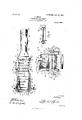
- Figure 1 is a side elevation of my invention.
- Fig. 2 is a longitudinal sectional'view thereof.
- Fig. 3 is a top plan view of the invention with the trough removed.
- Fig. 4 is an end view of the invention with the stacker tube swung back upon the machine.
- Fig. 5 is a detail perspective view of the hanger arranged between the corresponding ends of the sills and the base section of the stacker tube.
- Fig. 6 ]S a detail vlew of the fan casing.
- Fig. 7 18 a detail view of the brackets for supporting the fan wheel shaft.
- Fig. 8 is a detail view of a portion of the stacker.
- the reference charac ters 1 and 2 designate the usual side sills of a machine of the present character whose forward ends are connected by means of a cross piece 3 in the manner illustrated.
- a cross piece 3 mounted upon the upper faces of the sills 1. and 2 at the rear ends thereof are alining ournal boxes or bearings at in which a shaft 5 is journaled and upon which latter is loosely mounted, a heater 6 having longitudinal alining wings 7.
- a hanger 8 has its opposite upwardly directed side portions 9 provided with alining perforations 10 at their upper ends through which the aforesaid beater shaft '5 passes. It will be seen that the upwardly directed portions 9 lie parallel with the inner faces of the corresponding sills 1 and 2 and that the hanger 8 thereof extends beneath the sills for the reception of the contracted end 11 of the fan casing 12 which latter is secured thereto by means of rivets, bolts or the like and with the circular portion of the fan casing secured in any suitable manner to the inner faces of the sills 1 and 2.
- the free edge of the hanger 8 of the hanger has a tongue 13 struck up therefrom intermediate the side members 9 forming an opening 14 for a purpose presently explained.
- a fan 15 is fixedly secured upon a transverse shaft 16 arranged transversely of and projecti ng through the openings 17 of the fan casing 12, the-said shaft being supported in the manner stated through the instrumentality of suitable brackets 17 and 18.
- These brackets 17 and 18 are of a substantially V-shape with their leg portions secured to the outer faces of the side sills by means of rivets, belts or the like 19 with the shaft 16 journaled through the perforations or .open ings 20 at their bight portion, the legs of the bracket 17 being bent inwardly as at 21 and then downwardly in a vertical direction as at 22 to lie substantially in alinement with the inner face of the corresponding sill whereby the pulley wheels 23 and 24 at one end of the shaft 16 may be arranged for the reception of belts hereinafter described.
- the other bracket 18 is not bent in the manner described with reference to the bracket 17 but the fan shaft 16 is provided. with pulleys 25 and 26 at its opposite end, the pulley wheels at the opposite end of said shaft being arranged adjacent the outer faces of the corresponding brackets.
- brackets 28 and 29 Secured by means of belts or the like 27 upon the outer faces of the sills 1 and 2 are brackets 28 and 29, each of which has a laterally directed extension 30 provided with a passage 31 leading through the corresponding bracket.
- Journaled in the said extensions of the brackets and arranged transversely of the machine is a drive shaft 32 carrying a driving pulley 33 at one of its ends and other pulleys 34 and 35 disposed fixedly thereupon and arranged between the inner faces of the brackets and the outer faces of the sills of the corresponding brackets and sills, as clearly shown in the drawings.
- the inner section 39 of the stacker tube is provided with wings 40 and 41 provided with alining perforations 42 for engagement with the beater shaft between the inner faces of the sills and the correspondingly upwardly directed portions 9 of the aforesaid hanger and whereby the tube may be swung backwardly and forwardly over the machine.
- the inner bottom edge of the said section 39 of the stacker tube has an ear 43 depending therefrom and directed downwardly and provided with a perforation 44 for the reception of one end of the short transverse shaft 44 having its opposite end journaled in the perforation 45 of the depending car 46 arranged in alinement with the aforesaid ear, the outer end of the said short transverse shaft 44 having pulleys 45 and 46 thereon adjacent the outer faces of the depending ear 46 as clearly shown in the drawings.
- the first named ear 43 of the section 39 is arranged upon one side of an opening designed to register with the opening 14 of the aforesaid hanger 8 and that a pulley wheel 46 is journaled on the said short transverse shaft 44 adjacent to the ear 43 over which passes a belt 47 connecting the pulley 48 journaled in the depending ears 49 of the section 50 of the stacker tube.
- This pulley wheel 48 is ournaled over a notch or opening 51 in the under-face of the tube section 50 in a manner similar to the disposition of the pulley 46 whereby the pulleys may rotate freely.
- the tube belt 47 is provided with a series of teeth for action upon the straw to carry it upwardly through the tube and to prevent clogging therein especially when the straw is in a damp condition.
- the intermediate sections 52 and 53 of the tube are arranged telescopically with relation to each other and with respect to the section 50, there being a head 54 pivotally mounted upon the outer end of the section 50 which latter has its under portion cut away to enlarge the opening at the upper end of the stacker tube as shown.
- the under edge of the section 39 is designed to contact with the longitudinal stop 55 arranged upon the under-face of-the body portion 8 of the aforesaid hanger, the stop being so far inwardly from the edge of the said body portion 8 as to permit an overlapping of the said section 39 with the hanger.
- the stacker tube can be swung over the sills and when swung thereover, the up wardly directed shield portion 39 of the section 39 passes the beater and downwardly therebetween and a transverse shaft 56 journaled in the sills 1 and 2, the body portion of the stacker tube resting at its free end upon the table 57 within the trough formed by the side pieces 58 and 59 connected at one end by the cross piece 60.
- a foraminated plate or sieve 61 Arranged intermediate the table 57 and the said transverse shaft 56 is a foraminated plate or sieve 61 through which grain blown over the machine may pass and be fed into a receptacle of-the machine not shown by way of the spout 62 fixedly secured in any suitably manner to the sills 1 and 2 in advance of the fan wheel casing 12.
- a transversely of the ma chine and journaled in the sills 1 and 2 at the ends of the latter opposite to the ends in which the transverse shaft 56 is ournaled is another shaft 62.
- shafts 56 and 62 are arranged preferably in alinernent and each has a pair of pulley wheels 63 and 64 respectively mounted thereupon over which travels an endless conveyor apron 65, the apron working under and above the table. 57' and the foraminated plate or sieve 61 as: clearly shown in the drawings.
- a pulleywheel 66 for a purpose presently explained.
- a belt 69 which engages over the pulley 45.” on the short transverse shaft 44 whilefroin the pulley 46 of the said short shaft 44 leads.
- stacker tube belt being provided with teeth for the purpose of'preventing clogging of the straw within the tube when the straw is in a damp condition.
- the stacker tube is sectional with its sections telescoping for the purpose of adjustment and by which the tube may be collapsed. Another feature ofmy invention resides in the fact that I form the lower end of the stacker tube in such manner as to prevent grain from being blown over the machine and directing it over the endless apron and through the sieve when it may pass over or through the spout between the side sills as should now be well understood.
- a pneumatic stacker a frame, a fan wheel casing associated with the frame, a fan Wheel mounted within said casing, an endless conveyor apron associated with the frame, a stacker tube pivotally connected to one end of the frame, a toothed belt arranged to travel within the stacker tube, a beater arranged between the base of the tube and the corresponding end of the frame, a drive shaft, and connections between the drive shaft, the fan wheel, the beater, the conveyor apron. and the stacker tube belt to operate them simul taneously.
- a frame In a pneumatic stacker, a frame, a fan wheel associated with the frame, a casing enclosing the fan wheel and having a reduced end portion, a stacker tube pivoted. to one end of the frame and adapted to overlap the reduced portion of the casing, an endless conveyor apron arranged within the frame and terminating short of the base of the stacker tube, a beater arranged between the said end of the apron and the base of the stacker tube, a sieve arranged within the frame, a spout "communicating with said sieve, an endless toothed belt arranged to travel within the stacker tube, a drive shaft, and means in communication with the drive shaft for operating the said apron, the fan wheel, the beater and said endless apron simultaneously.
Description
PATBNTED APR. 23, 1907.
- 0. HOLEN.
PNEUMATIC STAGKER'.
APPLIGATION FILED MAY 31, 1905.
3 SHEETS-SHEET 1.
No. 851,237. PATENTBD APR. 23, 1907. w
0. HOLEN.
PNEUMATIC STAGKERI APPLIOATION rum) MAY 31, 1905.
3 SHEETS-SHEET B.
N3. 851,237. PATENTED APR. 23-, "1907.
0. HOLE'N.
PNEUMATIC STAGKBR. APPLICATION FILED MAY 31, 1905.
3 SHEETS-SHEET 3.
1,4: uomzlk PETERS cm. wasumcnm, n. c.
OLE HOLEN, OF BRITTON, SOUTH DAKOTA.
PNEUMATEC STACKERH Specification of Letters Patent.
Patented April 23, 1907.
Application filed May 81,1905. $erial No. 263,178.
To all whom it may concern.-
Be it known that I, OLE HOLEN, a citizen of the United States, residing at Britten, in the county of Marshall, State of South Dakota, have invented certain new and useful Improvements in Pneumatic Stackers and I do hereby declare the following to be a full, clear, and exact description of the invention, such as will enable others skilled in the art to which it appertains to make and use the same.
This invention relates to pneumatic stackers.
One object of the invention is to provide a comparatively simple, inexpensive, durable and eflicient means for stacking straw in the manner characteristic of machines to which the present machine relates.
Another object of the invention resides in the construction of a stacker wherein the stacker tube will be telescopic whereby it may be adjusted to different lengths and provided with means for preventing dry or damp straw from becoming clogged therein.
Astill further object of the invention is to arrange one or more sieves with relation to the fan and beater of the machine to save grain blown over by the pneumatic action of the fan.
With these and other objects in view, the present invention consists in the combination and arrangement of parts as will be hereinafter fully described, shown inthe accompanying drawings and particularly pointed out in the appended claims it being understood that changes in the form, proportion, size andminor details may be made within the scope of the claims, without departing from the spirit or sacrificing any of the advantages of the present invention.
In the accompanying drawings: Figure 1 is a side elevation of my invention. Fig. 2 is a longitudinal sectional'view thereof. Fig. 3 is a top plan view of the invention with the trough removed. Fig. 4 is an end view of the invention with the stacker tube swung back upon the machine. Fig. 5 is a detail perspective view of the hanger arranged between the corresponding ends of the sills and the base section of the stacker tube. Fig. 6 ]S a detail vlew of the fan casing. Fig. 7 18 a detail view of the brackets for supporting the fan wheel shaft. Fig. 8 is a detail view of a portion of the stacker.
Referring now more particularly to the accompanying drawings, the reference charac ters 1 and 2 designate the usual side sills of a machine of the present character whose forward ends are connected by means of a cross piece 3 in the manner illustrated. Mounted upon the upper faces of the sills 1. and 2 at the rear ends thereof are alining ournal boxes or bearings at in which a shaft 5 is journaled and upon which latter is loosely mounted, a heater 6 having longitudinal alining wings 7.
A hanger 8 .has its opposite upwardly directed side portions 9 provided with alining perforations 10 at their upper ends through which the aforesaid beater shaft '5 passes. It will be seen that the upwardly directed portions 9 lie parallel with the inner faces of the corresponding sills 1 and 2 and that the hanger 8 thereof extends beneath the sills for the reception of the contracted end 11 of the fan casing 12 which latter is secured thereto by means of rivets, bolts or the like and with the circular portion of the fan casing secured in any suitable manner to the inner faces of the sills 1 and 2. The free edge of the hanger 8 of the hanger has a tongue 13 struck up therefrom intermediate the side members 9 forming an opening 14 for a purpose presently explained.
A fan 15 is fixedly secured upon a transverse shaft 16 arranged transversely of and projecti ng through the openings 17 of the fan casing 12, the-said shaft being supported in the manner stated through the instrumentality of suitable brackets 17 and 18. These brackets 17 and 18 are of a substantially V-shape with their leg portions secured to the outer faces of the side sills by means of rivets, belts or the like 19 with the shaft 16 journaled through the perforations or .open ings 20 at their bight portion, the legs of the bracket 17 being bent inwardly as at 21 and then downwardly in a vertical direction as at 22 to lie substantially in alinement with the inner face of the corresponding sill whereby the pulley wheels 23 and 24 at one end of the shaft 16 may be arranged for the reception of belts hereinafter described. The other bracket 18 is not bent in the manner described with reference to the bracket 17 but the fan shaft 16 is provided. with pulleys 25 and 26 at its opposite end, the pulley wheels at the opposite end of said shaft being arranged adjacent the outer faces of the corresponding brackets.
Secured by means of belts or the like 27 upon the outer faces of the sills 1 and 2 are brackets 28 and 29, each of which has a laterally directed extension 30 provided with a passage 31 leading through the corresponding bracket. Journaled in the said extensions of the brackets and arranged transversely of the machine is a drive shaft 32 carrying a driving pulley 33 at one of its ends and other pulleys 34 and 35 disposed fixedly thereupon and arranged between the inner faces of the brackets and the outer faces of the sills of the corresponding brackets and sills, as clearly shown in the drawings. Connecting the pulley wheel 34 of the countershaft and the pulley 24 of the fan wheel shaft is a belt 36, there being another belt 37 arranged upon the opposite side of the machine and connecting the pulley wheels 35 and 25 of the counterand fan wheel shafts respectively. It will be seen, therefore, that upon rotation of the counter or drive shaft, the fan wheel shaft is operated through the instrumentality of said belts.
The inner section 39 of the stacker tube is provided with wings 40 and 41 provided with alining perforations 42 for engagement with the beater shaft between the inner faces of the sills and the correspondingly upwardly directed portions 9 of the aforesaid hanger and whereby the tube may be swung backwardly and forwardly over the machine. The inner bottom edge of the said section 39 of the stacker tube has an ear 43 depending therefrom and directed downwardly and provided with a perforation 44 for the reception of one end of the short transverse shaft 44 having its opposite end journaled in the perforation 45 of the depending car 46 arranged in alinement with the aforesaid ear, the outer end of the said short transverse shaft 44 having pulleys 45 and 46 thereon adjacent the outer faces of the depending ear 46 as clearly shown in the drawings. It will be observed that the first named ear 43 of the section 39 is arranged upon one side of an opening designed to register with the opening 14 of the aforesaid hanger 8 and that a pulley wheel 46 is journaled on the said short transverse shaft 44 adjacent to the ear 43 over which passes a belt 47 connecting the pulley 48 journaled in the depending ears 49 of the section 50 of the stacker tube. This pulley wheel 48 is ournaled over a notch or opening 51 in the under-face of the tube section 50 in a manner similar to the disposition of the pulley 46 whereby the pulleys may rotate freely. The tube belt 47 is provided with a series of teeth for action upon the straw to carry it upwardly through the tube and to prevent clogging therein especially when the straw is in a damp condition. The intermediate sections 52 and 53 of the tube are arranged telescopically with relation to each other and with respect to the section 50, there being a head 54 pivotally mounted upon the outer end of the section 50 which latter has its under portion cut away to enlarge the opening at the upper end of the stacker tube as shown.
In order to prevent the stacker tube falling too far downward with respect to the machine, the under edge of the section 39 is designed to contact with the longitudinal stop 55 arranged upon the under-face of-the body portion 8 of the aforesaid hanger, the stop being so far inwardly from the edge of the said body portion 8 as to permit an overlapping of the said section 39 with the hanger. Of course the stacker tube can be swung over the sills and when swung thereover, the up wardly directed shield portion 39 of the section 39 passes the beater and downwardly therebetween and a transverse shaft 56 journaled in the sills 1 and 2, the body portion of the stacker tube resting at its free end upon the table 57 within the trough formed by the side pieces 58 and 59 connected at one end by the cross piece 60. Arranged intermediate the table 57 and the said transverse shaft 56 is a foraminated plate or sieve 61 through which grain blown over the machine may pass and be fed into a receptacle of-the machine not shown by way of the spout 62 fixedly secured in any suitably manner to the sills 1 and 2 in advance of the fan wheel casing 12. Arranged transversely of the ma chine and journaled in the sills 1 and 2 at the ends of the latter opposite to the ends in which the transverse shaft 56 is ournaled is another shaft 62. These shafts 56 and 62 are arranged preferably in alinernent and each has a pair of pulley wheels 63 and 64 respectively mounted thereupon over which travels an endless conveyor apron 65, the apron working under and above the table. 57' and the foraminated plate or sieve 61 as: clearly shown in the drawings. Upon the shaft 56 eXteriorly of the sill 1 is a pulleywheel 66 for a purpose presently explained. Leading from the pulley 24 of the shaft 16 is a belt 69 which engages over the pulley 45." on the short transverse shaft 44 whilefroin the pulley 46 of the said short shaft 44 leads. a belt 67 over the pulley 70 of the beater shaft, there being a belt 68 leading from the pulley wheel 26 of the shaft 16 to the pulley of the apron shafts as clearly shown in the draw ings.
It will now be understood that upon rnoti on of the drive shaft the fan is rotated to gether with the beater, the endless apron and also the stacker tube belt through the instrumentality of the several shafts being connected together through the instrumentality of the aforesaid belt connections. It will also be, understood that if straw be placed upon the apron within the trough, the same will be. conveyed to the lower end of the stacker tube and forced upwardly through the latter and out of its up er end, the beater being arranged at the ase of the tube for the purpose of beating the straw in the usual manner, the
stacker tube belt being provided with teeth for the purpose of'preventing clogging of the straw within the tube when the straw is in a damp condition. It will also be understood that the stacker tube is sectional with its sections telescoping for the purpose of adjustment and by which the tube may be collapsed. Another feature ofmy invention resides in the fact that I form the lower end of the stacker tube in such manner as to prevent grain from being blown over the machine and directing it over the endless apron and through the sieve when it may pass over or through the spout between the side sills as should now be well understood.
What is claimed is:
1. In a pneumatic stacker, a frame, a fan wheel casing associated with the frame, a fan Wheel mounted within said casing, an endless conveyor apron associated with the frame, a stacker tube pivotally connected to one end of the frame, a toothed belt arranged to travel within the stacker tube, a beater arranged between the base of the tube and the corresponding end of the frame, a drive shaft, and connections between the drive shaft, the fan wheel, the beater, the conveyor apron. and the stacker tube belt to operate them simul taneously.
2. In a pneumatic stacker, a frame, a fan wheel associated with the frame, a casing enclosing the fan wheel and having a reduced end portion, a stacker tube pivoted. to one end of the frame and adapted to overlap the reduced portion of the casing, an endless conveyor apron arranged within the frame and terminating short of the base of the stacker tube, a beater arranged between the said end of the apron and the base of the stacker tube, a sieve arranged within the frame, a spout "communicating with said sieve, an endless toothed belt arranged to travel within the stacker tube, a drive shaft, and means in communication with the drive shaft for operating the said apron, the fan wheel, the beater and said endless apron simultaneously.
In testimony whereof, I affix my signature, in presence of two witnesses.
OLE HOLEN.
Witnesses JOHN F. WILSON, W. H. INGERSOLL.
Priority Applications (1)
| Application Number | Priority Date | Filing Date | Title |
|---|---|---|---|
| US26317305A US851237A (en) | 1905-05-31 | 1905-05-31 | Pneumatic stacker. |
Applications Claiming Priority (1)
| Application Number | Priority Date | Filing Date | Title |
|---|---|---|---|
| US26317305A US851237A (en) | 1905-05-31 | 1905-05-31 | Pneumatic stacker. |
Publications (1)
| Publication Number | Publication Date |
|---|---|
| US851237A true US851237A (en) | 1907-04-23 |
Family
ID=2919695
Family Applications (1)
| Application Number | Title | Priority Date | Filing Date |
|---|---|---|---|
| US26317305A Expired - Lifetime US851237A (en) | 1905-05-31 | 1905-05-31 | Pneumatic stacker. |
Country Status (1)
| Country | Link |
|---|---|
| US (1) | US851237A (en) |
Cited By (1)
| Publication number | Priority date | Publication date | Assignee | Title |
|---|---|---|---|---|
| US2629978A (en) * | 1949-05-14 | 1953-03-03 | Case Co J I | Ensilage harvester |
-
1905
- 1905-05-31 US US26317305A patent/US851237A/en not_active Expired - Lifetime
Cited By (1)
| Publication number | Priority date | Publication date | Assignee | Title |
|---|---|---|---|---|
| US2629978A (en) * | 1949-05-14 | 1953-03-03 | Case Co J I | Ensilage harvester |
Similar Documents
| Publication | Publication Date | Title |
|---|---|---|
| US2877057A (en) | Ensilage loader | |
| US851237A (en) | Pneumatic stacker. | |
| US1306586A (en) | Beet digging and topping machine | |
| US730671A (en) | Cane-harvester. | |
| US326443A (en) | Grain harvester and binder | |
| US1338045A (en) | Straw-spreader | |
| US750642A (en) | Joseph e | |
| US756655A (en) | Corn-husking machine. | |
| US1254750A (en) | Threshing-machine. | |
| US195184A (en) | Improvement in grain-separators | |
| US498323A (en) | Reaper | |
| US1291938A (en) | Combined corn snapper, husker, and sifter. | |
| US748640A (en) | Pneumatic straw-stacker | |
| US374513A (en) | Band-cutter and feeder | |
| US1535500A (en) | Corn husker | |
| US207554A (en) | Improvement in harvesters | |
| US873829A (en) | Pneumatic stacker. | |
| US864238A (en) | Corn-husking machine. | |
| US362244A (en) | Machine for cutting off the soiled butts of grain-stalks | |
| US881113A (en) | Attachment for binders. | |
| US539814A (en) | Band-cutter and feeder | |
| US436136A (en) | Corn-husking and fodder-preparing machine | |
| US947562A (en) | Husking and shredding machine. | |
| US140305A (en) | Improvement in corn-harvesters | |
| US533723A (en) | Machine for cutting green corn |