US8511676B2 - Medium feeding device and image forming apparatus - Google Patents
Medium feeding device and image forming apparatus Download PDFInfo
- Publication number
- US8511676B2 US8511676B2 US13/352,385 US201213352385A US8511676B2 US 8511676 B2 US8511676 B2 US 8511676B2 US 201213352385 A US201213352385 A US 201213352385A US 8511676 B2 US8511676 B2 US 8511676B2
- Authority
- US
- United States
- Prior art keywords
- medium
- gear
- feeding
- driving force
- sheet
- Prior art date
- Legal status (The legal status is an assumption and is not a legal conclusion. Google has not performed a legal analysis and makes no representation as to the accuracy of the status listed.)
- Active
Links
- 230000005540 biological transmission Effects 0.000 claims abstract description 68
- 230000007246 mechanism Effects 0.000 claims abstract description 59
- 238000001514 detection method Methods 0.000 claims abstract description 5
- 230000009471 action Effects 0.000 claims description 6
- 238000000926 separation method Methods 0.000 claims description 3
- 210000000078 claw Anatomy 0.000 description 53
- 230000003028 elevating effect Effects 0.000 description 43
- 238000000034 method Methods 0.000 description 17
- 230000008569 process Effects 0.000 description 17
- 230000002441 reversible effect Effects 0.000 description 14
- 230000007423 decrease Effects 0.000 description 7
- 230000008901 benefit Effects 0.000 description 6
- 238000004140 cleaning Methods 0.000 description 5
- 238000010586 diagram Methods 0.000 description 4
- 238000012840 feeding operation Methods 0.000 description 3
- 229910052736 halogen Inorganic materials 0.000 description 3
- 150000002367 halogens Chemical class 0.000 description 3
- 230000004048 modification Effects 0.000 description 3
- 238000012986 modification Methods 0.000 description 3
- 230000009467 reduction Effects 0.000 description 3
- 230000002159 abnormal effect Effects 0.000 description 2
- 230000000670 limiting effect Effects 0.000 description 2
- 239000002344 surface layer Substances 0.000 description 2
- 238000011144 upstream manufacturing Methods 0.000 description 2
- 239000003086 colorant Substances 0.000 description 1
- 230000003247 decreasing effect Effects 0.000 description 1
- 238000005265 energy consumption Methods 0.000 description 1
- 238000010438 heat treatment Methods 0.000 description 1
- 238000012544 monitoring process Methods 0.000 description 1
- 230000000149 penetrating effect Effects 0.000 description 1
- 230000002265 prevention Effects 0.000 description 1
- 230000002829 reductive effect Effects 0.000 description 1
- 238000007790 scraping Methods 0.000 description 1
- 230000003068 static effect Effects 0.000 description 1
- 239000000725 suspension Substances 0.000 description 1
Images


Classifications
-
- B—PERFORMING OPERATIONS; TRANSPORTING
- B65—CONVEYING; PACKING; STORING; HANDLING THIN OR FILAMENTARY MATERIAL
- B65H—HANDLING THIN OR FILAMENTARY MATERIAL, e.g. SHEETS, WEBS, CABLES
- B65H1/00—Supports or magazines for piles from which articles are to be separated
- B65H1/08—Supports or magazines for piles from which articles are to be separated with means for advancing the articles to present the articles to the separating device
- B65H1/14—Supports or magazines for piles from which articles are to be separated with means for advancing the articles to present the articles to the separating device comprising positively-acting mechanical devices
-
- B—PERFORMING OPERATIONS; TRANSPORTING
- B65—CONVEYING; PACKING; STORING; HANDLING THIN OR FILAMENTARY MATERIAL
- B65H—HANDLING THIN OR FILAMENTARY MATERIAL, e.g. SHEETS, WEBS, CABLES
- B65H2403/00—Power transmission; Driving means
- B65H2403/40—Toothed gearings
- B65H2403/48—Other
- B65H2403/481—Planetary
-
- B—PERFORMING OPERATIONS; TRANSPORTING
- B65—CONVEYING; PACKING; STORING; HANDLING THIN OR FILAMENTARY MATERIAL
- B65H—HANDLING THIN OR FILAMENTARY MATERIAL, e.g. SHEETS, WEBS, CABLES
- B65H2403/00—Power transmission; Driving means
- B65H2403/70—Clutches; Couplings
- B65H2403/72—Clutches, brakes, e.g. one-way clutch +F204
-
- B—PERFORMING OPERATIONS; TRANSPORTING
- B65—CONVEYING; PACKING; STORING; HANDLING THIN OR FILAMENTARY MATERIAL
- B65H—HANDLING THIN OR FILAMENTARY MATERIAL, e.g. SHEETS, WEBS, CABLES
- B65H2405/00—Parts for holding the handled material
- B65H2405/10—Cassettes, holders, bins, decks, trays, supports or magazines for sheets stacked substantially horizontally
- B65H2405/11—Parts and details thereof
- B65H2405/111—Bottom
- B65H2405/1117—Bottom pivotable, e.g. around an axis perpendicular to transport direction, e.g. arranged at rear side of sheet support
-
- B—PERFORMING OPERATIONS; TRANSPORTING
- B65—CONVEYING; PACKING; STORING; HANDLING THIN OR FILAMENTARY MATERIAL
- B65H—HANDLING THIN OR FILAMENTARY MATERIAL, e.g. SHEETS, WEBS, CABLES
- B65H2511/00—Dimensions; Position; Numbers; Identification; Occurrences
- B65H2511/20—Location in space
-
- B—PERFORMING OPERATIONS; TRANSPORTING
- B65—CONVEYING; PACKING; STORING; HANDLING THIN OR FILAMENTARY MATERIAL
- B65H—HANDLING THIN OR FILAMENTARY MATERIAL, e.g. SHEETS, WEBS, CABLES
- B65H2511/00—Dimensions; Position; Numbers; Identification; Occurrences
- B65H2511/50—Occurence
- B65H2511/51—Presence
-
- B—PERFORMING OPERATIONS; TRANSPORTING
- B65—CONVEYING; PACKING; STORING; HANDLING THIN OR FILAMENTARY MATERIAL
- B65H—HANDLING THIN OR FILAMENTARY MATERIAL, e.g. SHEETS, WEBS, CABLES
- B65H2801/00—Application field
- B65H2801/03—Image reproduction devices
- B65H2801/06—Office-type machines, e.g. photocopiers
Definitions
- the present invention relates to a medium feeding device for feeding a medium such as a printing paper, and an image forming apparatus having the medium feeding device.
- a general image forming apparatus includes a medium feeding device that feeds a medium, and an image forming portion that forms an image on the medium using electrophotography.
- the medium feeding device includes a medium placing plate on which a stack of the media is placed, and a pickup roller provided so as to contact the uppermost medium of the stack on the medium. The pickup roller feeds the media one by one.
- a height of the medium placing plate needs be adjusted. Therefore, there is proposed a medium feeding device including a spring is provided so as to press the medium placing from below, and an elevating arm is provided so as to abut against the medium placing plate from above.
- the height of the medium placing plate is controlled by driving the elevating arm using an exclusive motor (see, for example, Japanese Laid-open Patent Publication No. 2005-3520264).
- the medium feeding device further includes a height sensor for detecting a height of the medium placed on the medium placing plate, and a position sensor for detecting a home-position of the elevating arm.
- the conventional medium feeding device needs to be provided with an exclusive motor for moving the medium placing plate upward and downward.
- it is intended to provide a medium feeding device and an image forming unit capable of moving a medium upward and downward without using an exclusive motor.
- a medium feeding device including a main body, a medium placing member mounted to the main body so that the medium placing member is movable upward and downward, a feeding mechanism shiftably mounted to the main body, the feeding mechanism contacting a surface of the medium and feeding the medium in a predetermined direction, a conveying mechanism for conveying the medium fed by the feeding mechanism, a lifting unit that moves the medium placing member toward the feeding mechanism, a medium detecting unit for detecting presence and absence of the medium on the medium placing member, a driving source for driving at least one of the lifting unit and the conveying mechanism, a driving force transmission unit for transmitting a driving force of the driving source to the lifting unit, and a control unit that controls the driving source.
- the driving force transmission unit includes a first switching unit that connects or disconnects a transmission of the driving force from the driving source to the lifting unit based on a shifting of the feeding mechanism caused by a movement of the medium placing member, and a second switching unit that connects or disconnects a transmission of the driving force from the driving source to the lifting unit based on control by the control unit.
- the control unit causes the second switching unit to transmit the driving force to the lifting unit so as to move the medium placing member upward based on detection by the medium detecting unit.
- the first switching unit disconnects the transmission of the driving force to the lifting unit, so that the medium placing member is held at the predetermined position.
- the control unit causes the second switching unit to disconnect the transmission of the driving force to the lifting unit so that the medium placing member moves downward.
- FIG. 1 is a side view showing a basic configuration of an image forming apparatus according to the first embodiment of the present invention
- FIG. 2 is a perspective view showing an MPT according to the first embodiment of the present invention
- FIG. 3 is a sectional view showing an MPT according to the first embodiment of the present invention.
- FIG. 4 is a perspective view showing a main frame of the MPT and components mounted on the main frame according to the first embodiment of the present invention
- FIGS. 5A and 5B are top and bottom perspective views of a pickup frame of the MPT according to the first embodiment of the present invention.
- FIG. 5C is an enlarged perspective view showing a part of the pickup frame shown in FIGS. 5A and 5B ;
- FIG. 6 is a perspective view showing a swinging shaft of the MPT according to the first embodiment of the present invention.
- FIG. 7 is a perspective view showing the swinging shaft, an arm and a driving force transmission portion according to the first embodiment of the present invention.
- FIG. 8 is a perspective view showing the swinging shaft, the arm and the driving force transmission portion according to the first embodiment of the present invention.
- FIG. 9A is a perspective view showing the main frame of the MPT and an MPT cover according to the first embodiment of the present invention.
- FIG. 9B is an enlarged perspective view showing a part of the main frame of the MPT and the MPT cover shown in FIG. 9A ;
- FIG. 10A is a perspective view showing the driving force transmission portion according to the first embodiment of the present invention.
- FIG. 10B is a schematic view showing a driving force transmission path of the driving force transmission portion shown in FIG. 10A ;
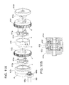
- FIGS. 11A and 11B are an exploded perspective view and a sectional view showing a gear portion of the driving force transmission portion of the MPT according to the first embodiment of the present invention
- FIGS. 12A and 12B are a plan view and a perspective view showing a state where a reset ratchet of the MPT is locked by a cam gear according to the first embodiment of the present invention
- FIGS. 12C and 12D are a plan view and a perspective view showing a state where the reset ratchet of the MPT is not locked by the cam gear according to the first embodiment of the present invention
- FIG. 13 is a timing chart showing an example of a rotation angle of the cam gear of the MPT and an output from a photo coupler according to the first embodiment of the present invention
- FIGS. 14A and 14B are exploded perspective views showing driving force transmission states of the driving force transmission portion of the MPT according to the first embodiment of the present invention
- FIG. 15 is an exploded perspective view showing a driving force transmission state of the driving force transmission portion of the MPT according to the first embodiment of the present invention.
- FIGS. 16A and 16B are exploded perspective views showing driving force transmission states of the driving force transmission portion of the MPT according to the first embodiment of the present invention
- FIG. 17 is a block diagram showing a control system of the image forming apparatus according to the first embodiment of the present invention.
- FIGS. 18A and 18B are side views showing an operation of a sheet placing plate of the MPT according to the first embodiment of the present invention.
- FIG. 19 is a flow chart showing an operation of the MPT according to the first embodiment of the present invention.
- FIGS. 20A and 20B are an exploded perspective view and a perspective view showing a lever portion of a sheet placing plate of an MPT according to the second embodiment of the present invention
- FIGS. 21A , 21 B and 21 C are schematic views showing an operation of a pickup frame, a lever portion and an elevating ratchet of the MPT according to the second embodiment of the present invention
- FIGS. 22A and 22B are perspective views respectively showing a lift gear and an internal tooth gear of an MPT according to the third embodiment of the present invention.
- FIGS. 23A and 23B are sectional views showing operations of the lift gear and the internal tooth gear of the MPT according to the third embodiment of the present invention.
- FIGS. 24A and 24B are sectional views showing meshing states between the lift gear and the internal tooth gear of the MPT according to the third embodiment of the present invention.
- FIG. 25A is a perspective view showing of a driving force transmission portion of an MPT according to the fourth embodiment of the present invention.
- FIG. 25B is a schematic view showing a driving force transmission path of the driving force transmission portion of the MPT according to the fourth embodiment of the present invention.
- FIG. 26 is a block diagram showing a control system of an image forming apparatus according to the fourth embodiment of the present invention.
- FIG. 27 is a flow chart showing an operation of the MPT according to the fourth embodiment of the present invention.
- FIG. 28 is a schematic view showing a driving force transmission path of an MPT according to the fifth embodiment of the present invention.
- FIG. 29 is a flow chart showing an operation of the MPT according to the fifth embodiment of the present invention.
- FIG. 30 is a schematic view showing a driving force transmission path of an MPT according to a modification of the fifth embodiment of the present invention.
- FIG. 1 is a schematic view showing an image forming apparatus 10 according to the first embodiment of the present invention.
- the image forming apparatus 1 includes a sheet tray 100 in which a stack of sheets (media) 101 is stored.
- the sheet tray 100 is detachably mounted to a lower part of a main body 11 of the image forming apparatus 10 .
- the sheet tray 100 includes a sheet placing plate 102 for placing the sheets 101 thereon, and a lift-up lever 103 for lifting the sheet placing plate 102 , and a pickup roller 202 for individually feeding the sheets 101 on the sheet placing plate 102 .
- the sheet placing plate 102 is swingably supported at a not shown supporting shaft.
- the lift-up lever 103 is provided on a feeding side (i.e., the right in FIG. 1 ) of the sheet tray 100 .
- the lift-up lever 103 is mounted to a rotation shaft 103 a rotated by a lift-up motor 104 .
- a driving force of the lift-up motor 104 is releasably transmitted to the rotation shaft 103 a .
- the sheet tray 100 includes an upward movement detecting unit 201 for detecting that the uppermost sheet 101 of the stack on the sheet placing plate 102 reaches a predetermined height (i.e., a height at which the uppermost sheet the contacts the pickup roller 202 ), a sheet remaining amount detecting sensor 205 for detecting a remaining amount of the sheets 101 on the sheet placing plate 102 .
- a predetermined height i.e., a height at which the uppermost sheet the contacts the pickup roller 202
- a sheet remaining amount detecting sensor 205 for detecting a remaining amount of the sheets 101 on the sheet placing plate 102 .
- the lift-up lever 103 When the sheet tray 100 is mounted to the main body 11 of the image forming apparatus 10 , the lift-up lever 103 is connected to the lift-up motor 104 , and the driving force of the lift-up motor 104 becomes transmittable to the lift-up lever 103 .
- a control unit 62 (not shown) of the image forming apparatus 10 drives the lift-up motor 104 , the lift-up lever 103 rotates to thereby lift the sheet placing plate 102 upward, and the sheets 101 placed on the sheet placing plate 102 moves upward.
- the control unit 62 stops the lift-up motor 104 based on a detection signal outputted by the upward movement detecting unit 201 . In this state, the pickup roller 202 rotates to feed the sheet 101 on the sheet placing plate 102 .
- a feeding roller 203 and a retard roller 204 are provided on a feeding side (i.e., right side) of the pickup roller 202 .
- the feeding roller 203 and the retard roller 204 contact each other.
- the pickup roller 202 , the feeding roller 203 and the retard roller 204 constitute a sheet feeding portion 200 .
- the pickup roller 202 and the feeding roller 203 are rotated by a feeding motor 72 ( FIG. 17 ) indirections shown by arrows in FIG. 1 .
- the pickup roller 202 an the feeding roller 203 respectively have one-way clutches therein, and are able to rotate idly even when the feeding motor 72 stops.
- the pickup roller 202 contacts the uppermost sheet 101 of the stack placed on the sheet placing plate 102 , and rotates so as to feed the sheet 101 .
- the retard roller 204 generates a torque in a direction shown by an arrow in FIG. 1 . Even when the pickup roller 202 feeds a plurality of the sheets 101 , the feed roller 203 and the retard roller 204 separate the sheets 101 so as to individually feed the sheets 101 into a conveying path.
- a pair of conveying rollers 302 for correcting a skew of the sheet 101 At a downstream side of the sheet feeding portion 200 in a conveying direction of the sheet 101 , a pair of conveying rollers 302 for correcting a skew of the sheet 101 , guide members 312 and 313 for guiding the sheet 101 from the sheet feeding portion 200 to the conveying rollers 302 , and another pair of conveying rollers 304 for conveying the sheet 101 to an image forming portion 400 described later.
- a sheet sensor 301 for detecting a passage of the sheet 101 is provided at a downstream side of the conveying rollers 302 in the conveying direction of the sheet 101 .
- a sheet sensor 303 for determining rotation-start timing of the conveying rollers 304 and a writing sensor for determining writing-start timing at the image forming unit 400 are respectively provided on an upstream side and a downstream side of the conveying rollers 304 .
- the conveying rollers 302 and 304 are respectively rotated by driving forces transmitted from conveying motors 73 and 74 ( FIG. 17 ) via not shown gears or the like, and controlled by a feeding-and-conveying control unit 67 ( FIG. 17 ).
- a multi-purpose tray (MPT) 600 as a medium feeding device is provided on a side (i.e., a right side in FIG. 1 ) of the image forming apparatus 10 .
- the MPT 600 includes a sheet placing plate 604 as a medium placing plate for placing a stack of sheets 606 as media, a pickup roller 602 as a feeding mechanism for individually feeding the sheets 606 on the sheet placing plate 604 , a feeding roller 601 for feeding the sheet 606 (fed by the sheet placing plate 604 ) to the main body 11 of the image forming apparatus 10 , and a retard roller 603 provided contacting the feeding roller 601 for separating the sheets 11 fed by the pickup roller 602 .
- a detailed description of the MPT 600 will be made later.
- the image forming apparatus 10 includes the image forming portion 400 including four process units 430 K, 430 Y, 430 M and 430 C that form images using toners (i.e., developers) of yellow, magenta, cyan and black.
- the process units 430 K, 430 Y, 430 M and 430 C are arranged in this order from an upstream side (i.e., the right in FIG. 1 ) of the conveying path of the sheet 101 .
- the process units 430 K, 430 Y, 430 M and 430 C are detachably mounted to the main body 11 of the image forming apparatus 10 .
- the process units 430 K, 430 Y, 430 M and 430 C have the same configuration, and are collectively referred to as the process unit 430 .
- the process unit 430 includes a photosensitive drum 431 as a latent image bearing body.
- the photosensitive drum 431 is rotatably supported, and is rotated by a not shown motor in a direction shown by an arrow in FIG. 1 .
- a charging roller 432 as a charging member
- an exposure device 433 as a developer bearing body
- a cleaning blade 435 as a cleaning member
- the charging roller 432 uniformly charges a surface of the photosensitive drum 431 .
- the exposure device 433 exposes the surface of the photosensitive drum 431 based on image date to form a latent image.
- the developing roller 434 develops the latent image on the surface of the photosensitive drum 431 to form a toner image.
- the cleaning blade 435 removes a residual toner (that remains on the surface of the photosensitive drum 431 after the toner image is transferred to the sheet) from the surface of the photosensitive drum 431 .
- a toner cartridge 436 as a developer storing portion for storing the toner to be supplied to the developing roller 432 is provided above the developing roller 434 . Respective rollers and the photosensitive drum 341 are rotated by driving forces transmitted from not shown driving sources via gears or the like.
- a transfer belt unit 460 is provided below the process units 430 K, 430 Y, 430 M and 430 C in FIG. 1 .
- the transfer belt unit 460 includes a transfer belt (i.e., a conveying belt) 461 that electrostatically absorbs and conveys the sheet 101 , further includes a driving roller 462 and a tension roller 463 around which the transfer belt 461 is stretched.
- the driving roller 462 is rotated by a driving force transmitted from a belt driving motor 76 ( FIG. 17 ) via not shown gears or the like, and is controlled by a belt driving control unit 69 ( FIG. 17 ) described later.
- the transfer belt 461 is moved by the rotation of the driving roller 462 .
- a cleaning blade 465 is provided for scraping off the toner adhering to the transfer belt 461
- a toner box 466 is provided for storing the scrapped-off by the cleaning blade 465 .
- Transfer rollers 464 are provided contacting the respective photosensitive drums 431 of the process units 430 K, 430 Y, 430 M and 430 C.
- the transfer rollers 464 are pressed against the photosensitive drums 431 via the transfer belt 461 .
- Each of the transfer rollers 464 has a resilient surface layer composed of rubber or the like having an electrical conductivity.
- the transfer roller 464 is applied with an electric potential for generating a difference in electric potential between the surface of the transfer roller 464 and the photosensitive drum 431 . Rotations of respective parts and voltages applied to respective parts of the image forming portion 400 are controlled by an image forming control unit 66 ( FIG. 17 ).
- a fixing portion 500 is provided at a downstream side (i.e., the left in FIG. 1 ) of the image forming unit 400 (i.e., the process cartridges 430 K, 430 Y, 430 M and 430 C) in the conveying direction of the sheet 101 .
- the fixing portion 500 includes an upper roller 501 and a lower roller 502 respectively having resilient surface layers.
- the upper roller 501 and the lower roller 502 have halogen lamps 503 a and 503 b as internal heat sources.
- the fixing portion 500 applies heat and pressure to the toner image on the sheet 101 conveyed from the image forming portion 400 , so that the toner image is molten and is fixed to the sheet 101 . Operations of respective parts of the fixing portion 500 are controlled by a fixing control unit 70 ( FIG. 17 ).
- Three pairs of ejection rollers 504 a , 504 b and 504 c are provided at a downstream side (i.e., the left in FIG. 1 ) of the fixing portion 500 in the conveying direction of the sheet 101 .
- the ejection rollers 504 a , 504 b and 504 c eject the sheet 101 to a stacker portion 505 provided on an upper cover 12 of the image forming apparatus 10 .
- the ejection rollers 504 a , 504 b and 504 c are rotated by a driving force transmitted from a conveying motor 75 ( FIG. 17 ) via not shown gears or the like, and is controlled by the feeding-and-conveying control unit 67 ( FIG. 17 ).
- a sheet sensor 506 is provided at a downstream side of the fixing portion 500 for determining rotation-start timings of the ejection rollers 504 a , 504 b and 504 c.
- FIG. 2 is a perspective view showing the MPT 600 .
- FIG. 3 is a sectional view taken along line III-III in FIG. 2 .
- a vertical direction is defined as Z direction.
- XY plane perpendicular to the Z direction
- Y direction A direction perpendicular to both of the X direction and the Z direction.
- the Y direction corresponds to a direction in which the sheet 606 is fed out from the MPT 600 .
- the MPT 600 includes a main frame 607 as a main body fixed to the main body 11 of the image forming apparatus 10 , and a pickup frame 611 as a movable body mounted to the main frame 607 mounted to the main frame 607 .
- the pickup frame 611 rotatably supports the feeding roller 601 and the pickup roller 602 .
- the feeding roller 601 and the pickup roller 602 both have axial directions in the X direction, and are adjacent to each other in the Y direction.
- the pickup frame 611 is mounted to the main frame 607 so that the pickup frame 611 is swingable about an axis O 1 ( FIG. 3 ) in the X direction.
- the axis O 1 also defines a rotation axis of the feeding roller 601 .
- An MPT cover 613 as a cover member is mounted to the main frame 607 so that the MPT cover 613 is swingable about an axis O 3 in the X direction.
- the MPT cover 613 engages a supporting hole 613 b formed on a lower end of the main frame 607 , and is supported so as to be swingable about the axis O 3 .
- arms 609 L and 609 R as arm members are mounted to the main frame 607 so that the arms 609 L and 609 R are swingable about an axis O 2 ( FIG. 3 ).
- the arms 609 L and 609 R have cam pins 609 c that engages cam grooves 613 c formed on both sides of the MPT cover 613 in the X direction. With the arms 609 L and 609 R, the MPT cover 613 is supported by the main frame 607 in a suspension manner.
- the MPT cover 613 is swingable between an upright position where the MPT cover 613 is retracted in a space inside the main frame 607 and a lying position where the MPT cover 613 protrudes outside from the main frame 607 as shown in FIG. 2 .
- the MPT cover 613 swings together with the arms 609 L and 609 R.
- the MPT cover 613 has a lock lever 613 a that engages an engaging portion (not shown) of the main frame 607 when the MPT cover 613 is in the upright position.
- a sheet placing plate 604 as a medium placing member is mounted to the MPT 613 for placing the sheets 606 .
- Supporting pins 604 a are formed on both sides of the sheet placing plate 604 in the X direction.
- the supporting pins 604 a engage guide grooves 613 d formed on the MPT cover 613 , with which the sheet placing plate 604 is swingable about the axis in the X direction.
- a swinging shaft 605 ( FIG. 3 ) as a lifting unit abuts against the sheet placing plate 604 from below.
- the swinging shaft 605 pushes the sheet placing plate 604 upward toward the pickup roller 602 using a driving force transmitted from a feeding motor 71 ( FIG. 17 ) as a driving source via a driving force transmitting portion (i.e., a driving force transmitting mechanism) 612 .
- a driving force transmitting portion i.e., a driving force transmitting mechanism 612 .
- An upper surface of the sheet placing plate 604 (or a surface of the uppermost sheet 606 when the sheets 606 are placed on the sheet placing plate 604 ) contacts the pickup roller 602 .
- a pair of side guides 610 L and 610 R are mounted to the sheet placing plate 604 so that the side guides 610 L and 610 R are movable in the X direction.
- the side guides 610 L and 610 R define both ends of the sheet 606 in the widthwise direction.
- a support guide 608 a is reversibly mounted to the MPT cover 613
- a slidable support guide 608 b is mounted to the support guide 608 a so as to protrude from the support guide 608 a.
- the MPT 600 includes a feeding roller 601 and a retard roller 603 are provided at a downstream side (i.e. right in FIG. 3 ) thereof in a feeding direction of the sheet 606 .
- the feeding roller 601 and the retard roller 603 face each other in the Z direction.
- the retard roller 603 is applied with a torque (i.e., a separation force) for separating the sheets 606 .
- the retard roller 603 is supported by the retard frame 603 a swingably mounted to the main frame 607 , and is pressed against the feeding roller 601 by a spring 603 b.
- FIG. 4 is a perspective view showing the main frame 607 and components mounted thereto.
- the retard roller 603 is mounted to the retard frame 603 a ( FIG. 3 ).
- a sheet sensor 614 as a medium detecting unit is provided in the vicinity of the retard roller 603 .
- the sheet sensor 614 is used for determining presence or absence of the sheet 606 on the sheet placing plate 604 .
- the sheet sensor 614 includes, for example, a lever member and a photo coupler.
- FIGS. 5A and 5B are respectively top and bottom perspective views showing the pickup frame 611 .
- a shaft 601 a of the feeding roller 601 and a shaft of the pickup roller 602 are rotatably supported by the pickup frame 611 .
- a rotation axis of the shaft 601 a of the feeding roller 601 is the above described axis O 1 .
- a feeding driving gear 611 d as a selective transmission unit is provided on an end of a shaft 601 a of the feeding roller 601 .
- the feeding driving gear 611 d has a one-way clutch therein.
- the one-way clutch is locked, and the shaft 601 a rotates in the direction shown by the arrow “a”. Therefore, the feeding roller 601 rotates in the direction shown by the arrow “a”.
- the one-way clutch rotates idly, and a rotation of the feeding driving gear 611 d is not transmitted to the shaft 601 a . Therefore, the feeding roller 610 does not rotate.
- a rotation of the feeding roller 601 is transmitted to the pickup roller 602 via gears (not shown) provided in the pickup frame 611 , so that the pickup roller 602 rotates in the same direction as the pickup roller 602 . Therefore, when the feeding driving gear 611 d rotates in the direction shown by the arrow “a” in FIG. 5A , the feeding roller 601 and the pickup roller 602 both rotate in the direction shown by the arrow “a” in FIG. 5A . In contrast, when the feeding driving gear 611 d rotates in the direction shown by the arrow a′ in FIG. 5A , the feeding roller 601 and the pickup roller 602 do not rotate.
- torsion springs 611 e and 611 f are provided on both sides of the pickup frame 611 .
- the torsion springs 611 e and 611 f biases the pickup frame 611 in a direction (shown by an arrow “b”) in which the pickup roller 602 contacts the sheet 606 .
- Each of the torsion springs 611 e and 611 f has an end that abuts against a predetermined part of the main frame 607 so that the torsion springs 611 e and 611 f bias the pickup frame 611 .
- FIG. 5C is an enlarged perspective view showing an end portion of the pickup frame 611 in the X direction.
- a claw portion 611 g as a first switching unit is formed on an end portion of the pickup frame 611 on the feeding driving gear 611 d side.
- the claw portion 611 g of the pickup frame 611 engages ratchet claws w formed on an outer circumference of an elevating ratchet 612 f (described later) of a driving force transmission portion 612 .
- the claw portion 611 g moves apart from the ratchet claws w of the elevating ratchet 612 f when the pickup frame 611 moves upward together with the sheet placing plate 604 as will be described later.
- FIG. 6 is a perspective view showing the swinging shaft 605 .
- FIGS. 7 and 8 are perspective views showing the swinging shaft 605 , the arms 609 L and 609 R and the driving force transmission portion 612 .
- the swinging shaft 605 includes a shaft 605 a extending in the X direction along a bottom portion of the sheet placing plate 604 , and a pair of gears 605 b (i.e., planet gears) fixed to both ends of the shaft 605 a .
- the gears 605 b are fixed to the shaft 605 a so that phases of the gears 605 b match each other.
- the arms 609 L and 609 R have arc-shaped guide holes (grooves) 609 b .
- the arc-shaped guide holes 609 b are formed in a concentric fashion with a lift-up gear 612 k (described later) of the driving force transmitting portion 612 .
- Both ends of the shaft 605 a respectively engage the arc-shaped guide holes 609 b of the arms 609 L and 609 R. With such a structure, a swinging of the swinging shaft 605 is guided.
- the arms 609 L and 609 R have internal tooth racks 609 a as internal tooth portions.
- the internal tooth racks 609 a are formed in a concentric fashion with the lift-up gear 612 k (described later) of the driving force transmitting portion 612 .
- the gears 605 b fixed to both ends of the shaft 605 a mesh with the internal tooth racks 609 a .
- the gears 605 b rotate and revolve while meshing with the lift-up gear 612 k and the internal tooth racks 609 a , with the result that the swinging shaft 605 moves (swings) substantially upward or downward along the guide holes 609 b.
- FIG. 9A is a perspective view showing the main frame 607 and the MPT cover 613 .
- FIG. 9B is an enlarged view showing a part encircled by a dashed-two dotted line in FIG. 9A .
- the MPT cover 613 is swingable with respect to the main frame 607 as described above. When the MPT 600 is not used, the MPT cover 613 is swung to the upright position as shown by an arrow in FIG. 9A , and is retracted in the main frame 607 . As the MPT cover 613 swings, the arms 609 L and 609 R also swing about the axis O 2 ( FIG. 3 ) in the same direction as the MPT cover 613 .
- the swinging shaft 605 supported at the arc-shaped guide holes 609 b of the arms 609 L and 609 R move apart from the lift-up gear 612 k of the driving force transmission portion 612 as shown in FIG. 9B .
- FIG. 10A is a perspective view showing the driving force transmission portion 612 .
- the driving force transmission portion 612 has a bracket 612 a on an end in the X direction.
- the bracket 612 a has a plurality of posts rotatably supporting the respective gears.
- the driving force transmission portion 612 has another bracket (not shown) on the other end in the X direction so as to face the bracket 612 a .
- a reduction gear 612 b , an idle gear 612 c , a one-way gear 612 d , and a cam gear 612 m as a movable body and a photo coupler 612 n as a detecting unit are mounted to the bracket 612 a . These components will be described later.
- FIG. 10B is a schematic view showing a driving force transmission path of the driving force transmission portion 612 .
- the feeding driving gear 611 d (for transmitting the driving force to the feeding roller 601 ) is also shown in FIG. 10B .
- a rotation of the feeding motor 71 of the image forming apparatus 10 is transmitted to the reduction gear 612 b via not shown gears.
- the reduction gear 612 b meshes with the idle gear 612 c .
- the idle gear 612 c meshes with the one-way gear 612 d .
- the rotation of the feeding motor 71 is also transmitted to the feeding driving gear 611 d via not shown gears.
- arrows h (solid line) indicate rotating directions of the respective gears when the sheet 606 is being fed.
- the one-way clutch of the feeding driving gear 611 d is locked (that is, the one-way clutch transmits the rotation to the shaft 601 a ), and the feeding roller 601 and the pickup roller 602 rotate.
- a one-way clutch mechanism provided between the one-way gear 612 d and a driven gear 612 e (described later) is locked, and the driving force is transmitted to the swinging shaft 605 .
- arrows h′ (dashed line) indicate rotating directions opposite to those shown by the arrows h.
- the feeding driving gear 611 d rotates in the direction shown by the arrow h′
- the one-way clutch of the feeding driving gear 611 d rotates idly, and the feeding roller 601 and the pickup roller 602 do not rotate.
- the one-way clutch mechanism provided in the one-way gear 612 d (coupled with the driven gear 612 e ) rotates idly, and the driving force is not transmitted to the swinging shaft 605 .
- the rotation of the feeding motor 71 is also transmitted to the cam gear 612 m via gears and a one-way clutch mechanism (not shown).
- the cam gear 612 m rotates only in the direction shown by the arrow h′ by the action of the one-way clutch mechanism. Therefore, the cam gear 612 m does not rotate while the sheet 606 is being fed.
- FIGS. 11A and 11B are respectively an exploded perspective view and a sectional view showing gears of the driving force transmission portion 612 .
- the driving force transmission portion 612 includes the driven gear 612 e , a elevating ratchet 612 f , planet gears 612 g (with a planet gear holder 612 h ), a lock gear 612 i , a reset ratchet 612 j , planet gears 612 p (with a planet gear holder 612 q ) and a lift-up gear 612 which are coupled coaxially with the one-way gear 612 d and are arranged along the X direction in this order from the one-way gear 612 d side.
- These gears are supported by a common shaft 619 ( FIG. 10A ) omitted in FIG. 11A .
- the driven gear 612 e is provided adjacent to the one-way gear 612 d .
- the one-way clutch mechanism is provided between the one-way gear 612 d and the driven gear 612 e so that the driven gear 612 e follows the rotation of the one-way gear 612 d only when the one-way gear 612 d rotates in the direction shown by the arrow h.
- the driven gear 612 e has an external tooth portion that meshes with the planet gears 612 g as described later.
- the one-way gear 612 d and the driven gear 612 e constitute a sun gear (i.e., a third sun gear) having the one-way clutch mechanism.
- the one-way clutch mechanism can be configured as, for example, a mechanism using a coil spring or a mechanism using a needle bearing.
- the one-way clutch mechanism uses a coil spring, when the one-way gear 612 d rotates in the direction shown by the arrow h, the coil spring is wound tightly around shaft portions of the one-way gear 612 d and the driven gear 612 e so as to transmit the rotation to the driven gear 612 e.
- the elevating ratchet 612 f has a ring shape, and has a plurality of ratchet claws w (i.e., a to-be-engaged portion) on an outer circumference thereof.
- the driven gear 612 e is inserted into inside the elevating ratchet 612 f from the one-way gear 612 d side.
- Three planet gears 612 g i.e., third planet gears
- the planet gear holder 612 h is mounted to the elevating ratchet 612 f .
- the planet gear holder 612 h has a ring shape, and rotatably holds the planet gears 612 g .
- the planet gears 612 g mesh with the external tooth portion of the drive gear 612 e inserted into inside the elevating ratchet 612 f .
- the elevating ratchet 612 f and the planet gear holder 612 h constitute a second carrier that holds the planet gears 612 g so that the planet gears 612 g are able to revolve around the external tooth portion of the driven gear 612 e (i.e., the third sun gear).
- the lock gear 612 i as a second sun gear is constituted by two ring-shaped portions one of which has a larger diameter than the other.
- the ring-shaped portions i.e., a larger portion and a smaller portion
- An internal tooth portion b is formed on an inner circumference of the larger portion of the lock gear 612 i .
- the internal tooth portion b meshes with the planet gears 612 g .
- An external tooth portion e is formed on an outer circumference of the smaller portion of the lock gear 612 i .
- the external tooth portion e meshes with the planet gears 612 p .
- the lock gear 612 i is fixed to the shaft 619 ( FIG. 10A ) inserted inside the lock gear 612 i via a one-way clutch mechanism that rotates only in a direction shown by an arrow g.
- the shaft 619 is fixed to the bracket 612 a ( FIG. 10A ) and does not rotate. Therefore, the lock gear 612 i rotates only in the direction shown by the arrow g.
- the reset ratchet 612 j has a ring shape, and has a plurality of ratchet claws v (i.e., a to-be-engaged portion) on an outer circumference thereof.
- the smaller portion of the lock gear 612 i is inserted inside the reset ratchet 612 j.
- Three planet gears 612 p as second planet gears are rotatably supported by the planet gear holder 612 q .
- the planet gear holder 612 q is fixed to the reset ratchet 612 j .
- the planet gears 612 p mesh with the external tooth portion e of the smaller portion of the lock gear 612 i (inserted inside the reset ratchet 612 j ).
- the reset ratchet 612 j and the planet gear holder 612 q constitute a first carrier that holds the planet gears 612 p so that the planet gears 612 p are able to revolve around the external tooth portion e of the lock gear 612 i (i.e., the second sun gear).
- the lift-up gear 612 k as a first sun gear has an internal tooth portion c on an inner circumference on the one-way gear 612 d side.
- the internal tooth portion c mesh with the planet gears 612 p .
- the lift-up gear 612 k has an external tooth portion d that mesh with one of the gear 605 b (i.e., first planet gears) mounted on the swinging shaft 605 .
- three planet gears 612 g and three planet gears 612 p are provided.
- the number of the planet gears 612 g and 612 p can be more than three, or less than three as long as the planet gears 612 g and 612 p can transmit the driving force.
- FIGS. 12A and 12B are a front view and a perspective view showing a mechanism for locking a rotation of the reset ratchet 612 j .
- the above described cam gear 612 m has an axial direction in the X direction, and has a cam portion i which is adjacent to the reset ratchet 612 j . Further, the cam gear 612 m has an external tooth portion r that meshes with a gear (not shown) with which the rotation of the feeding motor 71 (in the direction shown by the arrow h′ in FIG. 10B ) is transmitted to the cam gear 612 m.
- a lock piece 612 o as a second switching unit is provided adjacent to the cam gear 612 m so that the lock piece 612 o is movable in the X direction.
- the lock piece 612 o has a cam portion j that engages the cam portion i of the cam gear 612 m .
- the lock piece 612 o has a claw portion m (i.e., a to-be-engaged portion) that engages the ratchet claws v on the outer circumference of the reset ratchet 612 j .
- a photo coupler 612 n is provided adjacent to the lock piece 612 o .
- the lock piece 612 o has a light shielding plate s having a window k.
- the photo coupler 612 n outputs HIGH signal.
- the window k of the lock piece 612 o is in the light path of the photo coupler 612 n
- the photo coupler 612 n outputs Low signal.
- the lock piece 612 o is biased by a spring 612 r in the X direction toward the cam gear 612 m.
- the claw portion m of the lock piece 612 o engages the ratchet claw v of the reset ratchet 612 j , so as to lock the rotation of the reset ratchet 612 j .
- the light shielding plate s of the lock piece 612 o blocks the light path of the photo coupler 612 n , and therefore the photo coupler 612 n outputs HIGH signal.
- FIG. 13 is a timing chart showing a relationship between a rotating angle of the cam gear 612 m , output from the photo coupler 612 n (HIGH/LOW), and a locking state of the reset ratchet 612 j .
- the timing chart of FIG. 13 is merely an example, and this embodiment is not limited to the timing chart of FIG. 13 .
- the claw portion m of the lock piece 612 o engages the ratchet claws v of the reset ratchet 612 j , and lock the rotation of the reset ratchet 612 j .
- the rotating angle of the cam gear 612 m is in another predetermined range (for example, from 130 to 360 degrees)
- the claw portion m of the lock piece 612 o moves apart from the ratchet claws v of the reset ratchet 612 j , and allows the rotation of the reset ratchet 612 j.
- FIGS. 14A , 14 B and 15 are exploded perspective views showing driving force transmission states at respective parts of the driving force transmission portion 612 .
- FIG. 14A shows a state where the lock piece 612 o engages the reset ratchet 612 j to lock the rotation of the reset ratchet 612 j , and the claw portion 611 g of the pickup frame 611 engages the ratchet claws w of the elevating ratchet 612 f to lock the rotation of the elevating ratchet 612 f .
- lock piece 612 o and the claw portion 611 g of the pickup frame 611 are illustrated with simplified shapes.
- the rotation of the reset ratchet 612 j is locked by the lock piece 612 o , and therefore the planet gears 612 p (that mesh with the external tooth portion e of the lock gear 612 i ) do not rotate, but respectively rotate in a direction shown by arrows. Therefore, the lift-up gear 612 k (having the internal tooth portion c that meshes with the planet gears 612 p ) rotes as shown by an arrow.
- the gear 605 b of the swinging shaft 605 meshes with the external tooth portion d of the lift-up gear 612 k , and also meshes with the internal tooth rack 609 a of the arm 609 R.
- the gear 605 b of the swinging shaft 605 rotates in a direction shown by an arrow, and also revolves around the lift-up gear 612 k in an opposite direction.
- the swinging shaft 605 moves upward, and pushes the sheet placing plate 604 upward.
- FIG. 14B shows a state where the lock piece 612 o engages the reset ratchet 612 j to lock the rotation of the reset ratchet 612 j , and the claw portion 611 g of the pickup frame 611 is apart from the elevating ratchet 612 f to release the locking on the rotation of the elevating ratchet 612 f.
- the lock gear 612 i (having the internal tooth portion b that meshes with the planet gears 612 g ) does not rotate in a direction shown by a dashed arrow by the action of the one-way clutch mechanism. Therefore, the planet gears 612 g respectively rotate in a direction shown by arrows and revolve in an opposite direction, so that the elevating ratchet 612 f rotates in the same direction as the revolving direction of the planet gears 612 . In this state, the lock gear 612 i does not rotate, and therefore the planet gears 612 p and the lift-up gear 612 k do not rotate. Therefore, the swinging shaft 605 does not move.
- FIG. 15 is a state where the lock piece 612 o moves apart from the reset ratchet 612 j to release the locking on the rotation of the reset ratchet 612 j , and the claw portion 611 g of the pickup frame 611 engages the elevating ratchet 612 f to lock the rotation of the elevating ratchet 612 f .
- the one-way gear 612 d rotates in the direction shown by the arrow h
- the driven gear 612 e also rotates in the direction shown by the arrow h.
- the planet gears 612 g (mounted to the elevating ratchet f via the planet gear holder 612 h ) do not revolve, but respectively rotate in a direction shown by arrows.
- the lock gear 612 i (having the internal tooth portion b that meshes with the planet gears 612 g ) rotates in the same direction as the rotating direction of the planet gears 612 g .
- the planet gears 612 p that mesh with the external tooth portion e of the lock gear 612 i ) respectively rotate in a direction shown by arrows.
- FIGS. 16A and 16B are exploded perspective views showing a state where the swinging shaft 605 is in an uppermost position (including a case where sheets 606 are placed on the sheet placing plate 604 ), and the one-way gear 612 d does not rotate.
- FIG. 16A shows a state where the lock piece 612 o engages the reset ratchet 612 j to lock the rotation of the reset ratchet 612 j , and the claw portion 611 g of the pickup frame 611 is apart from the elevating ratchet 612 f to release the locking on the rotation of the elevating ratchet 612 f .
- a downward force is applied to the swinging shaft 605 , due to a total weight of the swinging shaft 605 , the sheet placing plate 604 (omitted in FIG. 16A ) and the sheets 606 placed on the sheet placing plate 604 .
- a torque (in a direction to cause the swinging shaft 605 to move downward) is applied to the gear 605 b , the lift-up gear 612 k , the planet gears 612 p , the planet gear holder 612 q , the reset ratchet 612 j and the lock gear 612 i respectively in directions shown by dashed arrows.
- the rotation of the reset ratchet 612 j is locked by the lock piece 612 o (and therefore the revolving of the planet gears 612 p is also locked), and the lock gear 612 i does not rotate in the direction shown by the dashed arrow by the action of the one-way clutch mechanism.
- the planet gears 612 p that mesh with the external tooth portion e of the lock gear 612 i
- the lift-up gear 612 k (having the internal tooth portion c that meshes with the planet gears 612 p ) does not rotate.
- the swinging shaft 605 does not move downward.
- FIG. 16B shows a state where the lock piece 612 o moves apart from the reset ratchet 612 j to release the locking on the rotation of the reset ratchet 612 j , and the claw portion 611 g of the pickup frame 611 is apart from the elevating ratchet 612 f to release the locking on the rotation of the elevating ratchet 612 f .
- a downward force is applied to the swinging shaft 605 , due to a total weight of the swinging shaft 605 , the sheet placing plate 604 (omitted in FIG. 16B ) and the sheets 606 placed on the sheet placing plate 604 .
- a torque (in a direction to cause the swinging shaft 605 to move downward) is applied to the gear 605 b , the lift-up gear 612 k , the planet gears 612 p , the planet gear holder 612 q , the reset ratchet 612 j and the lock gear 612 i respectively in directions shown by dashed arrows.
- the lock gear 612 i does not rotate in the direction shown by the dashed arrow by the action of the one-way clutch mechanism, but the reset ratchet 612 j is rotatable. Therefore, the planet gears 612 p (that mesh with the external tooth portion e of the lock gear 612 i ) rotate and revolve.
- the lift-up gear 612 k (having the internal tooth portion c that meshes with the planet gears 612 p ) rotates in the same direction as the planet gears 612 p , and the swinging shaft 605 moves downward.
- the rotation of the elevating ratchet 612 f is locked by the claw portion 611 g of the pickup frame 611 .
- FIG. 17 is a block diagram showing a control system of the image forming apparatus 10 .
- the control system of the image forming apparatus 10 will be described with reference to FIGS. 1 and 17 .
- the control unit 62 of the image forming apparatus 10 includes, for example, a microprocessor, an ROM, an RAM, an IO port, a timer or the like.
- the control unit 62 receives printing data and control command from a not shown host device, and performs a whole printing operation of the image forming apparatus 10 .
- the control unit 62 receives various kinds of signals from an operation unit 63 and sensors 64 .
- the operation unit 63 has a display panel 63 b for displaying a condition of the image forming apparatus 10 , an operation key 63 a operated by an operator for inputting instructions, and the like.
- the sensors 64 for monitoring operating conditions of the image forming apparatus 10 include sheet sensors 301 , 303 and 506 for detecting the positions of the sheet along the conveying path, a writing sensor 305 , a temperature/humidity sensor, a density sensor, a slackening sensor, the sheet remaining amount detecting sensor 205 , the upward movement detecting unit 201 , a photo coupler 612 n and the like.
- the control unit 62 controls the image forming control unit 66 , the feeding-and-conveying control unit 67 , the belt driving control unit 69 and the fixing control unit 70 .
- the image forming control unit 66 controls operations of respective parts of the image forming portion 400 based on instruction from the control unit 62 .
- the image forming control unit 66 controls the rotations of the photosensitive drums 431 , the exposures of the exposure devices 433 of the process units 430 K, 430 Y, 430 M and 430 C.
- the feeding-and-conveying control unit 67 controls the feeding motor 72 and thereby controls the sheet feeding portion 200 (i.e., the pickup roller 202 , the feed roller 203 and the retard roller 204 ) so as to feed the sheet 101 .
- the control unit 62 receives instruction from the host device or the control unit 63 to feed the sheet 606 from the MPT 500 , the control unit 62 causes the feeding-and-conveying control unit 67 to control the feeding motor 71 and to control the MPT 600 (i.e., the feeding roller 601 , the pickup roller 602 and the retard roller 603 ) so as to feed the sheet 606 .
- the feeding-and-conveying control unit 67 also controls the conveying motors 73 , 74 and 75 and thereby controls the conveying rollers 304 and the ejection rollers 504 a , 504 b and 504 c so as to convey the sheet 101 (or the sheet 606 ).
- the feeding motor 71 is provided in the main body 11 of the image forming apparatus 10 , it is also possible to provide the feeding motor 71 in the MPT 600 .
- the belt driving control unit 69 controls the belt driving motor 76 based on the instruction from the control unit 62 and thereby controls the rotation of the driving roller 462 for driving the transfer belt 461 .
- the fixing control unit 70 includes a driving source for rotating the upper roller 501 and the lower roller 502 , a power source for heating the halogen lamps 503 a and 503 b , and the like, and controls the upper roller 501 and the lower roller 502 and the halogen lamps 503 a and 503 b based on the instruction from the control unit 62 .
- the MPT 600 and respective components for conveying the sheet 606 (fed from the MPT 600 ) toward the image forming portion 400 constitute a medium feeding device.
- FIGS. 18A and 18B are views for illustrating an operation of the sheet placing plate 604 of the MPT 600 .
- FIG. 19 is a flow chart showing an operation of the MPT 60 .
- step S 101 In a standby mode (step S 101 ) where the sheets 606 are not placed on the sheet placing plate 604 , the lock piece 612 o is apart from the reset ratchet 612 j .
- the sheet placing plate 604 is in a lowermost position (i.e., is not lifted up), and therefore the claw portion 611 g of the pickup frame 611 engages the elevating ratchet 612 f (see, FIG. 15 ).
- the control unit 62 When the control unit 62 receives printing data and control command from the host device (step S 102 ), the control unit 62 checks the presence or absence of the sheets 606 on the sheet placing plate 604 (step S 103 a ) using the sheet sensor 614 ( FIG. 4 ). When the presence of the sheets 606 is not detected by the sheet sensor 614 (NO in step S 103 a ), the control unit 62 causes the display panel 63 b to display a message (for example, an alarm) prompting an operator to set the sheets 606 on the sheet placing plate 604 (step S 103 b ). When the presence of the sheets 606 is detected by the sheet sensor 614 (YES in step S 103 a ), the control unit 62 causes the feeding motor 71 to start rotation in a reverse direction (step S 104 a ).
- a message for example, an alarm
- the rotating direction of the feeding motor 71 causing the one-way gear 612 d in the direction shown by the arrow h ( FIG. 10B ) is referred to as a “normal direction”.
- the rotating direction of the feeding motor 71 causing the one-way gear 612 d in the direction shown by the arrow h′ is referred to as a “reverse direction”.
- control unit 62 detects that the output of the photo coupler 612 n changes from LOW to HIGH (step S 104 b ), the control unit 62 causes the feeding-and-conveying control unit 67 to stop the feeding motor 71 (step S 104 c ).
- the control unit 62 causes the feeding-and-conveying control unit 67 to start the rotation of the feeding motor 71 in the normal direction (step S 105 a ).
- the rotation of the feeding motor 71 in the normal direction is transmitted to the pickup roller 602 via the feeding driving gear 611 d , and the pickup roller 602 rotates.
- the one-way gear 612 d rotates in the direction shown by the arrow h, and the swinging shaft 605 moves upward.
- the sheet placing plate 604 on which the sheets 606 are placed also moves upward.
- the sheet placing plate 604 moves (swings) upward, the uppermost sheet 606 of the stack (i.e., the sheets 606 ) placed on the sheet placing plate 604 contacts the pickup roller 602 that is rotating, and is fed toward the feeding roller 601 .
- the pickup frame 611 swings upward.
- the claw portion 611 g of the pickup frame 611 moves apart from the elevating ratchet 612 f , and release the locking on the rotation of the elevation ratchet 612 f . Therefore, as was described with reference to FIG. 14B , the elevating ratchet 612 f rotates idly, and the upward movement of the swinging shaft 605 (that is, the upward movement of the sheet placing plate 604 ) stops.
- the pickup roller 602 is not pushed by the sheets 606 on the sheet placing plate 604 as shown in FIG. 18A . Therefore, the pickup frame 611 swings downward, and the claw portion 611 g of the pickup frame 611 engages the elevating ratchet 612 f again. Therefore, a state where the rotation of the one-way gear 612 d is transmittable to the swinging shaft 605 is reached ( FIG. 14A ), and the swinging shaft 605 moves upward to push the sheet placing plate 604 upward.
- the control unit 62 stops the rotation of the feeding motor 71 at a predetermined timing before a trailing end of the sheet 606 (which is being fed) passes the pickup roller 602 (step S 105 b ). In this state, a leading end of the sheet 606 reaches the conveying rollers 304 . Thereafter, the sheet 606 is conveyed by the conveying rollers 304 , the transfer belt 461 and the like. While the feeding motor 71 stops, the rotation of the one-way gear 612 d also stops, and therefore the sheet placing plate 604 does not move upward. However, as shown in FIG. 16A , the lock piece 612 o engages the reset ratchet 612 j , and therefore the position of the swinging shaft 605 is maintained. In other words, the sheet placing plate 604 does not move downward.
- control unit 62 waits for the trailing end of the sheet 606 to pass the sheet sensor 303 ( FIG. 1 ) provided on the downstream side of the MPT 600 (step S 106 ), and checks whether there is printing command for printing the next page (step S 107 ).
- step S 107 If there is printing command for printing the next page (YES in step S 107 ), the control unit 62 checks the presence or absence of the sheets 606 on the sheet placing plate 604 using the sheet sensor 614 (step S 108 ). When the presence of the sheets 606 is detected by the sheet sensor 614 (YES in step S 108 ), the control unit 62 repeats the above described processes from the step S 105 a.
- the control unit 62 causes the feeding motor 71 to start rotating in the reverse direction (step S 109 a ).
- the feeding motor rotates in the reverse direction
- the cam gear 612 m rotates to move the lock piece 612 o in the X direction.
- the claw portion m of the lock piece 612 o moves apart from the reset ratchet 612 j , and releases the locking on the rotation of the reset ratchet 612 j .
- the reset ratchet 612 j becomes rotatable, the sheet placing plate 604 and the swinging shaft 605 move downward due their own weight as shown in FIG.
- step S 109 b the control unit 62 causes the feeding-and-conveying control unit 67 to stop the feeding motor 71 (step S 109 c ). Then, the control unit 62 causes the display panel 63 b to display a message (for example, an alarm) prompting the operator to set the sheets 606 on the sheet placing plate 604 (step S 110 ), and proceeds to the above described step 103 a.
- a message for example, an alarm
- step S 107 if there is no printing command for printing the next page (NO in step S 107 ), the control unit 62 determines the presence or absence of the sheets 606 on the sheet placing plate 604 using the sheet sensor (step S 111 ). If the presence of the sheets 606 is detected by the sheet sensor 614 (YES in step S 111 ), the control unit 62 proceeds to the above described step S 102 .
- step S 111 If the presence of the sheets 606 is not detected by the sheet sensor 614 (NO in step S 111 ), the control unit 62 causes the sheet placing plate 604 to move downward (steps S 112 a , S 112 b and S 112 C) in a similar manner to the above described steps 109 a through 109 c , and proceeds to the above described step S 102 .
- the sheet 606 fed by the pickup roller 602 is further fed by the feeding roller 601 , and is conveyed by the conveying rollers 304 ( FIG. 1 ) toward the image forming portion 400 .
- the transfer belt 461 absorbs the sheet 606 , and conveys the sheet 606 through the process units 430 K, 430 Y, 430 M and 430 C.
- toner images of respective colors are formed on the respective photosensitive drums 431 , and are transferred to the sheet 606 on the transfer belt 461 .
- the sheet 606 (to which the toner image is transferred) is conveyed to the fixing portion 500 , and the toner image is fixed to the sheet 606 .
- the sheet 606 to which the toner image is fixed is ejected to the stacker portion 505 by the ejection rollers 504 a , 504 b and 504 c.
- the sheet placing plate 604 can be moved upward and downward using the feeding motor 71 for rotating the pickup roller 602 . Therefore, it is not necessary to provide an exclusive motor for moving the sheet placing plate 604 upward and downward. Further, the number of the sensors required for the movement of the sheet placing plate 604 can be minimized. Accordingly, cost, size and energy consumption of the medium feeding device and the image forming apparatus can be relatively reduced.
- the second embodiment of the present invention will be described.
- components that are the same as those of the first embodiment are assigned the same reference numerals, and duplicate explanations thereof will be omitted.
- the second embodiment is different from the first embodiment in the structure of the claw portion 611 g ( 615 g ) of the pickup frame 611 .
- FIG. 20A is a perspective view showing an end portion of the pickup frame 611 in the X direction according to the second embodiment.
- the pickup frame 611 of the second embodiment includes a lever 615 as a lever member.
- the lever 615 is provided coaxially on the axis (i.e., the swinging axis of the pickup frame 611 ).
- the lever 615 includes a cylindrical body and a claw portion 615 a formed on the cylindrical body.
- the claw portion 615 a has the same shape as the claw portion 611 a ( FIG. 5C ) of the first embodiment.
- the lever 615 also includes a hole portion 615 b that extends in an arc-shape concentric with the axis O 1 .
- a post 611 h is formed on the end surface of the pickup frame 611 .
- the post portion 611 h is inserted into the hole portion 615 b.
- the lever 615 is supported by a shaft (not shown) penetrating through the lever 615 so that the lever 615 is swingable about the axis O 1 .
- a shaft not shown
- the lever 615 is swingable about the axis O 1 .
- the post portion 611 h is inserted into the hole portion 615 b of the lever 615 , a swingable range of the lever 615 about the axis O 1 is limited.
- FIGS. 21A , 21 B and 21 C are schematic view showing a relationship between an operation of the pickup frame 611 , the lever 615 and the elevating ratchet 612 f .
- FIG. 21A shows a state where the pickup roller 602 is pushed upward by the sheets 606 (omitted in FIG. 21 ) on the sheet placing plate 604 and the pickup frame 611 swings upward. This corresponds to the state shown in FIG. 18B described in the first embodiment.
- the lever 615 swings downward due to its own weight about the axis O 1 with respect to the pickup frame 611 .
- the post portion 611 h contacts an upper surface of the hole portion 615 b of the lever 615 , and prevents the lever 615 from further swinging downward.
- FIG. 21B shows a state where the number of sheets 606 on the sheet placing plate 604 decreases, and the pickup frame 611 swings downward. This corresponds to the state shown in FIG. 18A described in the first embodiment.
- the post portion 611 h also moves downward while contacting the upper surface of the hole portion 615 b . Therefore, the lever 615 moves downward, and the claw portion 615 a of the lever 615 engages the elevating ratchet 612 f .
- the pickup roller 602 held by the pickup frame 611 contacts the upper surface of the sheets 606 (the number of which decreases) on the sheet placing plate 604 .
- FIG. 21C shows a state where the pickup frame 611 further swings downward from the state shown in FIG. 21B .
- the pickup frame 611 and the lever 615 are independently swingable in this second embodiment, and therefore the pickup frame 611 can swing further downward even when the claw portion 615 a of the lever 615 engages the elevating ratchet 612 f (and therefore the lever 615 does not swings downward).
- the post portion 611 h is apart from the upper surface of the hole portion 615 b.
- the sheet placing plate 604 moves upward and the sheets 606 push the pickup roller 612 f in a state where the claw portion 611 g of the pickup frame 611 engages the elevating ratchet 612 f . Therefore, a biasing force with which the pickup roller 602 abuts against the sheets 606 is also applied to the claw portion 611 g of the pickup frame 611 , with the result that a contacting force between the pickup frame 611 and the sheets 606 may decrease, or a contacting state may become uneven.
- the lever 615 having the claw portion 615 a and the pickup frame 611 holding the pickup roller 602 are independently swingable, and therefore the biasing force with which the pickup roller 602 abuts against the sheets 606 is not applied to the claw portion 615 a.
- An operation of the image forming apparatus 10 of the second embodiment is the same as that of the first embodiment.
- the difference in operation between the first and second embodiments is that the pickup frame 611 is swingable downward even when the claw portion 615 a of the lever 615 engages the elevating ratchet 612 f , and that the biasing force with which the pickup roller 602 abuts against the sheets 606 is not applied to the claw portion 615 a of the lever 615 .
- the following advantage can be achieved in addition to the advantages of the first embodiment. That is, according to the second embodiment, the contacting state between the pickup roller 602 and the sheets 606 can be made even, and therefore a skew or multiple feeding of the sheets 606 can be surely prevented.
- the third embodiment of the present invention will be described.
- components that are the same as those of the first and second embodiments are assigned the same reference numerals, and duplicate explanations thereof will be omitted.
- the third embodiment is different from the first embodiment in the structure of the lift-up gear 612 k.
- FIGS. 22A and 22B are perspective views of components of a lift-up gear of the third embodiment.
- the lift-up gear (i.e., the third sub gear) of the third embodiment corresponds to the lift-up gear 612 k of the first and second embodiments.
- the lift-up gear of the third embodiment is constituted by a combination of a lift gear 616 as a first member shown in FIG. 22A , and an internal tooth gear 617 as a second member shown in FIG. 22B .
- the lift gear 616 has an external tooth portion d that meshes with the gear 605 b ( FIG. 11A ) of the swinging shaft 605 .
- the internal tooth gear 617 has an internal tooth portion c ( FIG. 23 ) that meshes with the planet gears 612 p ( FIG. 11A ).
- the lift gear 616 and the internal tooth gear 617 both have substantially disk shape, and face each other in the direction of the rotation axis.
- the lift gear 616 has convexes 616 a and concaves 616 b (i.e., concave-convex surface) on a surface facing the internal tooth gear 617 .
- the convexes 616 a and concaves 616 b are arranged alternately and at constant intervals in a circumferential direction of the lift gear 616 .
- the internal tooth gear 617 has concaves 617 a and convexes 617 b (i.e., concave-convex surface) on a surface facing the lift gear 617 .
- the concaves 617 a and convexes 617 b are arranged alternately and at constant intervals in a circumferential direction of the internal tooth gear 617 .
- FIG. 23A is a sectional view showing a supporting structure of the lift gear 616 and the internal tooth gear 617 .
- the shaft 619 is fixed to the bracket 612 a of the driving force transmission portion 612 .
- the shaft 619 rotatably supports the lift gear 616 and the internal tooth gear 617 .
- the shaft 619 is inserted through respective hole portions formed at center portions of the lift gear 616 and the internal tooth gear 61 .
- a stopper ring 619 a is fixed to the shaft 619 for limiting a position of the internal tooth gear 617 in the axial direction.
- a spring 618 as a biasing member is provided between the bracket 612 a and the lift gear 616 .
- the lift gear 616 is biased by the spring 618 toward the internal tooth gear 617 .
- the spring 618 generates a biasing force P.
- the spring 618 when the convexes 616 a and the concaves 616 b of the lift gear 616 respectively engage the convexes 617 b and the concaves 617 a of the internal tooth gear 617 , the spring 618 generates a biasing force P′.
- the lift gear 616 and the internal tooth gear 617 are coupled with each other in such a manner that the convexes 616 a engage the concaves 617 a and the concaves 616 b engage the convexes 617 b ( FIG. 23A ).
- FIG. 24A is an enlarged sectional view showing a state where the convexes 616 a and the concaves 616 b of the lift gear 616 engage the concaves 617 a and the convexes 617 b of the internal tooth gear 617 .
- FIG. 24B is an enlarged sectional view showing a state where a slip occurs between the lift gear 616 and the internal tooth gear 617 .
- a necessary torque (applied to the lift gear 616 ) for moving the sheet placing plate 604 (on which the sheets 606 are placed) upward is expressed as a torque T.
- a torque when the slip occurs between the lift gear 616 and the internal tooth gear 617 as shown in FIG. 24B is expressed as a torque M.
- the biasing force P′ of the spring 618 is set so as to satisfy the relationship: M>T. Therefore, if a torque M greater than the necessary torque. T for moving the sheet placing plate 604 upward is applied to the lift gear 616 , the slip occurs between the lift gear 616 and the internal tooth gear 617 . Therefore, the lift gear 616 , the internal tooth gear 617 and the spring 618 constitute a torque clutch mechanism.
- An internal radius and an external radius of a region where the convexes and concaves of the lift gear 616 and the internal tooth gear 617 engage each other are respectively expressed as R 1 and R 2 ( FIG. 22B ).
- a tapered angle of the convexes and concaves of the lift gear 616 and the internal tooth gear 617 is expressed as ⁇ .
- a static friction coefficient between the lift gear 616 and the internal tooth gear 617 is expressed as ⁇ .
- An operation of the MPT of the third embodiment is the same as that of the first embodiment.
- the difference between the first and third embodiments is that, when the lift gear 616 is applied with the predetermined torque or more, a slip occurs between the lift gear 616 and the internal tooth gear 617 . That is, the lift gear 616 rotates idly. Therefore, when the lift gear 616 is applied with a large torque under abnormal conditions (for example, when an operator pushes the sheet placing plate 604 downward in a state where the sheet placing plate 604 is in the uppermost position), the lift gear 616 rotates idly, and therefore components such as gears are prevented from being damaged.
- the lift gear 616 rotates idly when the lift gear 616 is applied with the predetermined torque or more, and therefore damage to components can be prevented even when the lift gear 616 is applied with a large torque under abnormal conditions. Further, it becomes possible for the operator to push the sheet placing plate 604 downward in a state where the sheet placing plate 604 is in the uppermost position. For example, if the sheets of incorrect size have been set on the sheet placing plate 604 , the sheets can be easily removed from the sheet placing plate 604 .
- the torque is generated by bringing substantially disk-shaped members having concave-convex surfaces (i.e., the lift gear 616 and the internal tooth gear 617 ) into contact with each other.
- this embodiment is not limited to such a configuration, and it is only necessary that a slip occurs when applied with a predetermined torque or more.
- a torque limiting mechanism using a coil spring, or a torque generating mechanism using a friction plate can be used.
- the fourth embodiment of the present invention will be described.
- components that are the same as those of the first, second and third embodiment are assigned the same reference numerals, and duplicate explanations thereof are omitted.
- the fourth embodiment is different from the first embodiment in that the driving force is transmitted to the pickup roller 602 via a clutch 620 .
- FIG. 25A is a perspective view showing the pickup frame 611 , the driving force transmission portion 612 and the clutch 620 of the MPT 600 according to the fourth embodiment.
- FIG. 25B is a schematic view showing a transmission path of the driving force of the feeding motor 71 (i.e., a driving force transmission path) according to the fourth embodiment.
- the clutch 620 as a selective transmission unit is used instead of the feeding driving gear 611 d.
- the clutch 620 is provided on an end portion of the shaft 601 a of the feeding roller 601 .
- the clutch 620 is, for example, an electromagnetic clutch.
- the clutch 620 connects or disconnects the transmission of the driving force from the feeding motor 71 to the shaft 601 a of the feeding roller 601 .
- respective gears of the driving force transmission portion 612 rotate in the directions shown by arrows h in order to rotate the feeding roller 601 .
- the respective gears of the driving force transmission portion 612 rotate in the directions shown by arrows h′ in order to lock the rotation of the reset ratchet 612 j or release the locking on the rotation of the reset ratchet 612 j (i.e., in order to move the cam gear 612 m in the X direction).
- FIG. 26 is a block diagram showing a control system of the image forming apparatus 10 of the fourth embodiment.
- the control system of the image forming apparatus 10 of the fourth embodiment is substantially the same as that of the first embodiment ( FIG. 17 ).
- the control system of the image forming apparatus 10 of the fourth embodiment is different from that of the first embodiment in that the feeding-and-conveying control unit 67 also controls an operation of the clutch 620 based on the instruction from the control unit 62 .
- FIG. 27 is a flow chart showing the operation of the medium feeding device of the fourth embodiment.
- step S 201 In a standby mode (step S 201 ) where the sheets 606 are not placed on the sheet placing plate 604 , the lock piece 612 o is apart from the reset ratchet 612 j .
- the sheet placing plate 604 is in a lowermost position (i.e., is not lifted up), and therefore the claw portion 611 g of the pickup frame 611 engages the elevating ratchet 612 f (see, FIG. 15 ).
- the control unit 62 When the control unit 62 receives printing data and control command from the host device (step S 202 ), the control unit 62 checks the presence or absence of the sheets 606 on the sheet placing plate 604 (step S 203 a ) using the sheet sensor 614 . When the presence of the sheets 606 is not detected by the sheet sensor 614 (NO in step S 203 a ), the control unit 62 causes the display panel 63 b to display a message (for example, an alarm) prompting the operator to set the sheets 606 on the sheet placing plate 604 (step S 203 b ). When the presence of the sheets 606 is detected by the sheet sensor 614 (YES in step S 203 a ), the control unit 62 causes the feeding motor 71 to start rotation in the reverse direction (step S 204 a ).
- a message for example, an alarm
- the cam gear 612 m rotates to move the lock piece 612 o in the X direction.
- the claw portion m of the lock piece 612 o engages the reset ratchet 612 j , and locks the rotation of the reset ratchet 612 j . Therefore, a state where the rotation of the one-way gear 612 d in the normal direction (i.e., shown by the arrow h) is transmittable to the swinging shaft 605 ( FIG. 14A ) is reached.
- control unit 62 detects that the output of the photo coupler 612 n changes from LOW to HIGH (step S 204 b ), the control unit 62 causes the feeding-and-conveying control unit 67 to stop the feeding motor 71 (step S 204 c ).
- control unit 62 causes the feeding-and-conveying control unit 67 to start the rotation of the feeding motor 71 in the normal direction (step S 205 a ).
- the rotation of the feeding motor 71 in the normal direction is continued during a predetermined time period until the sheet placing plate 604 moves upward and the sheets 606 push the pickup roller 602 causing the claw portion 611 g of the pickup frame 611 (or a lever 615 described in the second embodiment) releases the locking on the rotation of the elevation ratchet 612 f.
- the one-way gear 612 d rotates in the direction shown by the arrow h, and the swinging shaft 605 moves upward as shown in FIG. 25B .
- the sheet placing plate 604 (on which the sheets 606 are placed) also moves upward.
- the clutch 620 is in a disconnecting state where the clutch 620 does not transmit the driving force.
- the control unit 62 causes the feeding-and-conveying control unit 67 to connect the clutch 620 (step S 206 a ). That is, the clutch 620 becomes able to transmit the driving force.
- the rotation of the feeding motor 71 in the normal direction is transmitted to the feeding roller 601 and the pickup roller 602 , and the sheet 606 is fed.
- the control unit 62 causes the feeding-and-conveying control unit 67 to disconnect the clutch 620 (step S 206 b ). That is, the clutch 620 is brought into the disconnecting state where the clutch 620 does not transmit the driving force.
- control unit 62 waits for the trailing end of the sheet 606 to pass the sheet sensor 303 provided on the downstream side of the MPT 600 (step S 207 ), and checks whether there is printing command for printing the next page (step S 208 ). If there is printing command for printing the next page (YES in step S 208 ), the control unit 62 checks the presence or absence of the sheets 606 on the sheet placing plate 604 using the sheet sensor 614 (step S 209 ). When the presence of the sheets 606 is detected by the sheet sensor 614 (YES in step S 209 ), the control unit 62 repeats the above described processes from the step S 206 a.
- the feeding motor 71 keeps rotating in the normal direction, and therefore the one-way gear 612 d keeps rotating in the normal direction. Therefore, when the number of the sheets 606 on the sheet placing plate 604 decreases, the sheet placing plate 604 moves upward according to a decreasing number of the sheets 606 as was described in the first embodiment.
- the control unit 62 stops the feeding motor 71 (step S 210 ), and then causes the feeding motor 71 to rotate in the reverse direction (step S 211 a ).
- the feeding motor 71 rotates in the reverse direction
- the cam gear 612 m rotates to move the lock piece 612 o in the X direction.
- the claw portion m of the lock piece 612 o moves apart from the reset ratchet 612 j , and releases the locking on the rotation of the reset ratchet 612 j .
- the control unit 62 detects that the output of the photo coupler 612 n changes from HIGH to LOW (step S 211 b )
- the control unit 62 causes the feeding-and-conveying control unit 67 to stop the feeding motor 71 (step S 211 c ).
- the control unit 62 causes the display panel 63 b to display a message (for example, an alarm) prompting the operator to set the sheets 606 on the sheet placing plate 604 (step S 212 ), and proceeds to the above described step 203 a.
- step S 208 if there is no printing command for printing the next page (NO in step S 208 ), the control unit 62 stops the feeding motor 71 (step S 213 ) and determines the presence or absence of the sheets 606 on the sheet placing plate 604 using the sheet sensor (step S 214 ). If the presence of the sheets 606 is detected by the sheet sensor 614 (YES in step S 214 ), the control unit 62 proceeds to the above described step S 202 .
- step S 214 the control unit 62 causes the sheet placing plate 604 to move downward (steps S 215 a , S 215 b and S 215 C) in a similar manner to the above described steps 211 a through 211 c , and proceeds to the above described step S 202 .
- the upward movement of the sheet placing plate 604 occurs during the feeding operation of the sheet 606 by the pickup roller 602 , and therefore there is a possibility that the sheet placing plate 604 moves upward while the sheet 606 is being fed by the pickup roller 602 .
- the feeding of the sheet 606 is performed while the clutch 620 is connected (step S 206 a ), and the upward movement of the sheet placing plate 604 is performed while the clutch 620 is disconnected.
- the decrease in the number of the sheets 606 on the sheet placing plate 604 occurs when the uppermost sheet 606 passes the pickup roller 602 . Therefore, the upper movement of the sheet placing plate 604 occurs when the uppermost sheet 606 passes the pickup roller 602 (step S 207 ).
- the following advantage can be achieved in addition to the advantages of the first embodiment. That is, according to the fourth embodiment, the feeding operation of the sheet 606 and the upward movement of the sheet placing plate 604 occur in separate time periods. Therefore, multiple feeding and jam of the sheets 606 can be prevented.
- the fourth embodiment is not limited to such a configuration. It is possible to use a component capable of connecting and disconnecting the transmission of the driving force to the feeding mechanism such as the pickup roller 602 . For example, it is possible to use a plunger solenoid or the like instead of the clutch 620 .
- the fifth embodiment of the present invention will be described.
- components that are the same as those of the first through fourth embodiment are assigned the same reference numerals, and duplicate explanations thereof will be omitted.
- the fifth embodiment is different from the first embodiment in that the one-way gear 612 d is driven by the driving forth of the conveying motor 74 .
- FIG. 28 is schematic view showing a driving force transmission path according to the fifth embodiment.
- the upward/downward movement of the sheet placing plate 604 is performed using the driving force generated by the conveying motor 74 ( FIG. 17 ) for driving the conveying rollers 304 ( FIG. 1 ) provided in the main body 11 of the image forming apparatus 10 .
- the conveying rollers 304 include a one-way clutch mechanism.
- the one-way clutch mechanism transmits the rotation, and the conveying rollers 304 rotate in directions shown by arrows h (solid lines) to convey the sheet 606 .
- the conveying motor 74 rotates in the reverse direction, the one-way clutch mechanism rotates idly (i.e., does not transmit the rotation), and the conveying rollers 304 do not rotate.
- the feeding driving gear 611 d having the one-way clutch mechanism is mounted to the shaft 601 a of the feeding roller 601 .
- the driving force of the feeding motor 71 is transmitted to the feeding driving gear 611 d .
- the configuration and function of the feeding driving gear 611 d are as described in the first embodiment.
- the one-way gear 612 d transmits the rotation in the direction shown by the arrow h (solid line) to the driven gear 612 e ( FIG. 14A ), but does not transmit the rotation in the direction shown by the arrow h′ (dashed line) to the driven gear 612 e .
- the cam gear 612 n has the one-way clutch mechanism, and rotates only in the direction shown by the arrow h′ (solid line).
- FIG. 29 is a flow chart showing the operation of the MPT 600 of the fifth embodiment.
- step S 301 In a standby mode (step S 301 ) where the sheets 606 are not placed on the sheet placing plate 604 , the lock piece 612 o is apart from the reset ratchet 612 j .
- the sheet placing plate 604 is in a lowermost position (i.e., is not lifted up), and therefore the claw portion 611 g of the pickup frame 611 engages the elevating ratchet 612 f (see, FIG. 15 ).
- the control unit 62 checks the presence or absence of the sheets 606 on the sheet placing plate 604 (step S 303 a ) using the sheet sensor 614 .
- the control unit 62 causes the display panel 63 b to display a message (for example, an alarm) prompting an operator to set the sheets 606 on the sheet placing plate 604 (step S 303 b ).
- the control unit 62 causes the conveying motor 74 to start rotation in a reverse direction (step S 304 a ).
- the cam gear 612 m rotates to move the lock piece 612 o in the X direction.
- the claw portion m of the lock piece 612 o engages the reset ratchet 612 j , and locks the rotation of the reset ratchet 612 j . Therefore, a state where the rotation of the one-way gear 612 d in the normal direction (i.e., shown by the arrow h) is transmittable to the swinging shaft 605 ( FIG. 14A ) is reached.
- control unit 62 detects that the output of the photo coupler 612 n changes from LOW to HIGH (step S 304 b ), the control unit 62 causes the feeding-and-conveying control unit 67 to stop the conveying motor 74 (step S 304 c ).
- the control unit 62 causes the feeding-and-conveying control unit 67 to rotate the conveying motor 74 in the normal direction (step S 304 d ).
- the conveying motor 74 rotates in the direction shown by the arrow h, and the swinging shaft 605 moves upward.
- the sheet placing plate 604 on which the sheets 606 are placed moves upward.
- the rotation of the conveying motor 74 in the normal direction is continued until the sheets 606 on the sheet placing plate 604 push the pickup roller 602 and the locking on the rotation of the elevation ratchet 612 f is released.
- the control unit 62 stops the conveying motor 74 (step S 304 e ).
- the control unit 62 causes the feeding-and-conveying control unit 67 to start the rotation of the feeding motor 71 in the normal direction (step S 305 a ).
- the rotation of the feeding motor 71 in the normal direction is transmitted to the pickup roller 602 via the feeding driving gear 611 d . Therefore, the pickup roller 602 and the feed roller 601 rotate, and feed the sheet 606 from the sheet placing plate 604 .
- the sheet 606 is detected by the sheet sensor 303 (step S 305 b ), it means that the leading end of the sheet 606 reaches the conveying rollers 304 .
- the feeding motor 71 keeps rotating in the normal direction, the leading end of the sheet 606 is pushed into a nip portion between the conveying rollers 304 that do not rotate. Therefore, even if a skew of the sheet 606 occurs, the leading end of the sheet 606 becomes parallel to the conveying rollers 304 , and the skew of the sheet 606 is corrected.
- control unit 62 causes the feeding-and-conveying control unit 67 to start rotating the conveying motor 74 in the normal direction (step S 305 c ).
- the conveying rollers 304 convey the sheet 606 while sandwiching the sheet 606 therebetween.
- the control unit 62 stops the normal rotation of the feeding motor 71 (step S 305 d ) at a predetermined timing before the sheet 606 passes the pickup roller 602 .
- the conveying motor 74 keeps rotating in the normal direction. Therefore, as was described in the first embodiment, the sheet placing plate 604 moves upward when the number of the sheets 606 (on the sheet placing place 604 ) decreases.
- the control unit 62 waits for the sheet 606 to pass the sheet sensor 303 (provided on the downstream side of the MPT 600 (step S 305 e ), and stops the conveying motor 74 at a timing when the trailing end of the sheet 606 passes the sheet sensor 303 and completely passes the conveying rollers 304 (step S 305 f ).
- control unit 62 checks whether there is printing command for printing the next page (step S 306 ). If there is printing command for printing the next page (YES in step S 306 ), the control unit 62 checks the presence or absence of the sheets 606 on the sheet placing plate 604 using the sheet sensor 614 (step S 307 ). When the presence of the sheets 606 is detected by the sheet sensor 614 (YES in step S 307 ), the control unit 62 repeats the above described processes from the step S 305 a.
- the control unit 62 causes the conveying motor 74 to start rotating in the reverse direction (step S 308 a ).
- the cam gear 612 m rotates to move the lock piece 612 o in the X direction.
- the claw portion m of the lock piece 612 o moves apart from the reset ratchet 612 j , and releases the locking on the rotation of the reset ratchet 612 j .
- step S 308 b the control unit 62 causes the feeding-and-conveying control unit 67 to stop the conveying motor 74 (step S 308 c ). Then, the control unit 62 causes the display panel 63 b to display a message (for example, an alarm) prompting the operator to set the sheets 606 on the sheet placing plate 604 (step S 309 ), and proceeds to the above described step 303 a.
- a message for example, an alarm
- step S 306 if there is no printing command for printing the next page (NO in step S 306 ), the control unit 62 determines the presence or absence of the sheets 606 on the sheet placing plate 604 using the sheet sensor (step S 310 ). If the presence of the sheets 606 is detected by the sheet sensor 614 (YES in step S 310 ), the control unit 62 proceeds to the above described step S 302 .
- step S 310 the control unit 62 causes the sheet placing plate 604 to move downward (steps S 311 a , S 311 b and S 311 C) in a similar manner to the above described steps 308 a through 308 c , and proceeds to the above described step S 302 .
- the clutch 620 is provided for performing the feeding operation of the sheet 606 (by the pickup roller 602 ) and the upward movement of the sheet placing plate 604 in separate time periods.
- the upward/downward movement of the sheet placing plate 604 is performed using the driving force of the conveying motor 74 . Therefore, the prevention of multiple feeding and jam of the sheets 606 can be achieved by using the one-way clutch gear (i.e., the feeding driving gear 611 d ) which is less expensive than the clutch 620 ( FIG. 25 ).
- the movement of the sheet placing plate 604 is performed using the driving force of the conveying motor 74 .
- a driving force of other motor for feeding or conveying the sheet 606 .
- a driving force of a belt driving motor 76 for rotating the driving roller 461 to move the transfer belt 461 of the transfer belt unit 460 .
- the present invention is not limited to such an image forming apparatus.
- the present invention is applicable to an apparatus that forms an image on a medium which is conveyed, for example, a color image forming apparatus using an intermediate transfer belt, a monochrome having a single process unit, or the like. Further, the present invention is applicable to a copier, a facsimile an automatic manuscript reading apparatus or the like. Furthermore, it is possible to use other media than sheets. In the above described first through fifth embodiments.
- these embodiments can be applied to a configuration for moving the sheet placing plate 102 of the sheet tray 100 in the image forming apparatus 10 .
Landscapes
- Engineering & Computer Science (AREA)
- Mechanical Engineering (AREA)
- Sheets, Magazines, And Separation Thereof (AREA)
Abstract
Description
R=2/3×(R23 −R13)/(R22 −R12)
F=M/R
M=P′×R×(sin θ−μ cos θ)/(cos θ−μ sin θ)
Claims (19)
Applications Claiming Priority (2)
| Application Number | Priority Date | Filing Date | Title |
|---|---|---|---|
| JP2011008443A JP5538248B2 (en) | 2011-01-19 | 2011-01-19 | Medium supply apparatus and image forming apparatus |
| JP2011-008443 | 2011-01-19 |
Publications (2)
| Publication Number | Publication Date |
|---|---|
| US20120187620A1 US20120187620A1 (en) | 2012-07-26 |
| US8511676B2 true US8511676B2 (en) | 2013-08-20 |
Family
ID=46543601
Family Applications (1)
| Application Number | Title | Priority Date | Filing Date |
|---|---|---|---|
| US13/352,385 Active US8511676B2 (en) | 2011-01-19 | 2012-01-18 | Medium feeding device and image forming apparatus |
Country Status (2)
| Country | Link |
|---|---|
| US (1) | US8511676B2 (en) |
| JP (1) | JP5538248B2 (en) |
Cited By (2)
| Publication number | Priority date | Publication date | Assignee | Title |
|---|---|---|---|---|
| US20160368722A1 (en) * | 2015-06-16 | 2016-12-22 | Konica Minolta, Inc | Sheet member supply device and image forming apparatus |
| US10183819B2 (en) * | 2016-10-25 | 2019-01-22 | Hewlett-Packard Development Company, L.P. | Assembly for printer having damped media tray |
Families Citing this family (9)
| Publication number | Priority date | Publication date | Assignee | Title |
|---|---|---|---|---|
| JP5971470B2 (en) * | 2012-08-08 | 2016-08-17 | セイコーエプソン株式会社 | Recording device |
| JP6127917B2 (en) * | 2013-10-31 | 2017-05-17 | ブラザー工業株式会社 | Image forming apparatus |
| KR101866992B1 (en) * | 2016-10-17 | 2018-06-14 | 주식회사 에이텍에이피 | Locking device for cassette push plate |
| JP6991770B2 (en) * | 2017-07-31 | 2022-01-13 | キヤノン株式会社 | Sheet transfer device and image forming device |
| JP6971697B2 (en) * | 2017-08-07 | 2021-11-24 | キヤノン株式会社 | Sheet feeding device and image forming device |
| KR20190140649A (en) * | 2018-06-12 | 2019-12-20 | 휴렛-팩커드 디벨롭먼트 컴퍼니, 엘.피. | Image forming apparatus for driving pickup roller |
| JP2020134539A (en) * | 2019-02-12 | 2020-08-31 | 京セラドキュメントソリューションズ株式会社 | Image forming apparatus |
| JP7316547B2 (en) * | 2019-11-08 | 2023-07-28 | 株式会社リコー | Multi-tray paper feeder and image forming device |
| JP7618415B2 (en) * | 2020-09-15 | 2025-01-21 | キヤノン株式会社 | Sheet detection device and image forming apparatus |
Citations (12)
| Publication number | Priority date | Publication date | Assignee | Title |
|---|---|---|---|---|
| US5501444A (en) * | 1993-01-18 | 1996-03-26 | Canon Kabushiki Kaisha | Sheet supply apparatus |
| US6824133B2 (en) * | 2002-10-17 | 2004-11-30 | Hewlett-Packard Development Company, L.P. | Stack monitoring method and system |
| US20040251600A1 (en) * | 2003-05-09 | 2004-12-16 | Fuji Xerox Co., Ltd. | Sheet feeding device and sheet processing apparatus |
| JP2005350264A (en) | 2004-05-14 | 2005-12-22 | Oki Data Corp | Medium supply apparatus and image forming apparatus |
| US6994341B2 (en) * | 2002-07-12 | 2006-02-07 | Canon Kabushiki Kaisha | Sheet feeding device and image forming apparatus equipped with the same |
| US7222847B2 (en) * | 2003-08-29 | 2007-05-29 | Canon Kabushiki Kaisha | Feeding apparatus and recording apparatus having the same |
| US7441767B2 (en) * | 2004-02-13 | 2008-10-28 | Oki Data Corporation | Sheet feeder with stacking member lifted by planetary gear system |
| US20110140341A1 (en) * | 2009-12-10 | 2011-06-16 | Canon Kabushiki Kaisha | Sheet feeding apparatus and image forming apparatus |
| US7984902B2 (en) * | 2007-07-04 | 2011-07-26 | Brother Kogyo Kabushiki Kaisha | Sheet feeding device and image forming apparatus |
| US20110233851A1 (en) * | 2010-03-26 | 2011-09-29 | Kyocera Mita Corporation | Sheet feeder and image forming apparatus provided with the same |
| US8152159B2 (en) * | 2008-09-08 | 2012-04-10 | Kyocera Mita Corporation | Sheet feeding device and image forming apparatus including a controlled elevator mechanism |
| US8177216B2 (en) * | 2007-02-26 | 2012-05-15 | Ricoh Company, Ltd. | Sheet conveying device with hold and transfer unit |
Family Cites Families (4)
| Publication number | Priority date | Publication date | Assignee | Title |
|---|---|---|---|---|
| JP3056421B2 (en) * | 1995-10-26 | 2000-06-26 | キヤノン株式会社 | Sheet material feeding device and image forming device |
| JP3815250B2 (en) * | 2001-04-25 | 2006-08-30 | 富士ゼロックス株式会社 | Sheet feeding device |
| JP3902744B2 (en) * | 2002-03-22 | 2007-04-11 | 株式会社リコー | Image forming apparatus |
| JP4582234B2 (en) * | 2008-10-29 | 2010-11-17 | ブラザー工業株式会社 | Image forming apparatus |
-
2011
- 2011-01-19 JP JP2011008443A patent/JP5538248B2/en not_active Expired - Fee Related
-
2012
- 2012-01-18 US US13/352,385 patent/US8511676B2/en active Active
Patent Citations (12)
| Publication number | Priority date | Publication date | Assignee | Title |
|---|---|---|---|---|
| US5501444A (en) * | 1993-01-18 | 1996-03-26 | Canon Kabushiki Kaisha | Sheet supply apparatus |
| US6994341B2 (en) * | 2002-07-12 | 2006-02-07 | Canon Kabushiki Kaisha | Sheet feeding device and image forming apparatus equipped with the same |
| US6824133B2 (en) * | 2002-10-17 | 2004-11-30 | Hewlett-Packard Development Company, L.P. | Stack monitoring method and system |
| US20040251600A1 (en) * | 2003-05-09 | 2004-12-16 | Fuji Xerox Co., Ltd. | Sheet feeding device and sheet processing apparatus |
| US7222847B2 (en) * | 2003-08-29 | 2007-05-29 | Canon Kabushiki Kaisha | Feeding apparatus and recording apparatus having the same |
| US7441767B2 (en) * | 2004-02-13 | 2008-10-28 | Oki Data Corporation | Sheet feeder with stacking member lifted by planetary gear system |
| JP2005350264A (en) | 2004-05-14 | 2005-12-22 | Oki Data Corp | Medium supply apparatus and image forming apparatus |
| US8177216B2 (en) * | 2007-02-26 | 2012-05-15 | Ricoh Company, Ltd. | Sheet conveying device with hold and transfer unit |
| US7984902B2 (en) * | 2007-07-04 | 2011-07-26 | Brother Kogyo Kabushiki Kaisha | Sheet feeding device and image forming apparatus |
| US8152159B2 (en) * | 2008-09-08 | 2012-04-10 | Kyocera Mita Corporation | Sheet feeding device and image forming apparatus including a controlled elevator mechanism |
| US20110140341A1 (en) * | 2009-12-10 | 2011-06-16 | Canon Kabushiki Kaisha | Sheet feeding apparatus and image forming apparatus |
| US20110233851A1 (en) * | 2010-03-26 | 2011-09-29 | Kyocera Mita Corporation | Sheet feeder and image forming apparatus provided with the same |
Cited By (3)
| Publication number | Priority date | Publication date | Assignee | Title |
|---|---|---|---|---|
| US20160368722A1 (en) * | 2015-06-16 | 2016-12-22 | Konica Minolta, Inc | Sheet member supply device and image forming apparatus |
| US9764911B2 (en) * | 2015-06-16 | 2017-09-19 | Konica Minolta, Inc. | Sheet member supply device and image forming apparatus |
| US10183819B2 (en) * | 2016-10-25 | 2019-01-22 | Hewlett-Packard Development Company, L.P. | Assembly for printer having damped media tray |
Also Published As
| Publication number | Publication date |
|---|---|
| JP5538248B2 (en) | 2014-07-02 |
| JP2012148853A (en) | 2012-08-09 |
| US20120187620A1 (en) | 2012-07-26 |
Similar Documents
| Publication | Publication Date | Title |
|---|---|---|
| US8511676B2 (en) | Medium feeding device and image forming apparatus | |
| US9873576B2 (en) | Sheet feeding apparatus and image forming apparatus | |
| JP2012158422A (en) | Sheet feeder and image forming apparatus | |
| US10589948B2 (en) | Sheet feeding apparatus | |
| JP5780749B2 (en) | Sheet feeding apparatus and image forming apparatus | |
| JP6890767B2 (en) | Contact / detachment mechanism, fixing device, transfer device and image forming device | |
| JP5545544B2 (en) | Driving device, fixing device, and image forming apparatus | |
| JP2015048165A (en) | Image forming apparatus | |
| JP6264573B2 (en) | Sheet material supply apparatus and image forming apparatus | |
| JP6655424B2 (en) | Image forming device | |
| JP6291807B2 (en) | Paper feeding device and image forming apparatus | |
| US9229381B2 (en) | Cleaning device, fixing device including the cleaning device, and image forming apparatus including the fixing device | |
| US10120318B2 (en) | Recording material feeding device with control of motor speed | |
| JP2017081674A (en) | Image forming apparatus | |
| JP6335598B2 (en) | Sheet feeding apparatus and image forming apparatus | |
| CN118922360A (en) | Sheet conveying device and image forming apparatus including the same | |
| JP3638793B2 (en) | Image forming apparatus | |
| JP6205694B2 (en) | Image forming apparatus, image forming control method, and image forming control program | |
| JP2018127346A (en) | Medium supply apparatus, image forming apparatus, and medium remaining amount detection apparatus | |
| JP2019069833A (en) | Sheet feeding device and image forming device | |
| WO2026048236A1 (en) | Sheet feeding device and image forming device | |
| JP2024134688A (en) | SHEET FEEDING DEVICE AND IMAGE FORMING APPARATUS | |
| JP6016598B2 (en) | Image forming apparatus | |
| CN119225135A (en) | Sheet storage device and image forming device having the same | |
| JP2010006540A (en) | Gear unit, paper feeder, and image forming device |
Legal Events
| Date | Code | Title | Description |
|---|---|---|---|
| AS | Assignment |
Owner name: OKI DATA CORPORATION, JAPAN Free format text: ASSIGNMENT OF ASSIGNORS INTEREST;ASSIGNOR:KITAMURA, MAKOTO;REEL/FRAME:027548/0426 Effective date: 20120105 |
|
| STCF | Information on status: patent grant |
Free format text: PATENTED CASE |
|
| FPAY | Fee payment |
Year of fee payment: 4 |
|
| MAFP | Maintenance fee payment |
Free format text: PAYMENT OF MAINTENANCE FEE, 8TH YEAR, LARGE ENTITY (ORIGINAL EVENT CODE: M1552); ENTITY STATUS OF PATENT OWNER: LARGE ENTITY Year of fee payment: 8 |
|
| AS | Assignment |
Owner name: OKI ELECTRIC INDUSTRY CO., LTD., JAPAN Free format text: MERGER;ASSIGNOR:OKI DATA CORPORATION;REEL/FRAME:059365/0145 Effective date: 20210401 |
|
| MAFP | Maintenance fee payment |
Free format text: PAYMENT OF MAINTENANCE FEE, 12TH YEAR, LARGE ENTITY (ORIGINAL EVENT CODE: M1553); ENTITY STATUS OF PATENT OWNER: LARGE ENTITY Year of fee payment: 12 |