US8508759B2 - Communication apparatus for displaying a screen using screen data and program of communication apparatus - Google Patents

Communication apparatus for displaying a screen using screen data and program of communication apparatus Download PDF

Info

Publication number
US8508759B2
US8508759B2 US13/289,922 US201113289922A US8508759B2 US 8508759 B2 US8508759 B2 US 8508759B2 US 201113289922 A US201113289922 A US 201113289922A US 8508759 B2 US8508759 B2 US 8508759B2
Authority
US
United States
Prior art keywords
screen
screen data
instruction
display
data
Prior art date
Legal status (The legal status is an assumption and is not a legal conclusion. Google has not performed a legal analysis and makes no representation as to the accuracy of the status listed.)
Active, expires
Application number
US13/289,922
Other versions
US20120113454A1 (en
Inventor
Yutaka Urakawa
Current Assignee (The listed assignees may be inaccurate. Google has not performed a legal analysis and makes no representation or warranty as to the accuracy of the list.)
Brother Industries Ltd
Original Assignee
Brother Industries Ltd
Priority date (The priority date is an assumption and is not a legal conclusion. Google has not performed a legal analysis and makes no representation as to the accuracy of the date listed.)
Filing date
Publication date
Application filed by Brother Industries Ltd filed Critical Brother Industries Ltd
Assigned to BROTHER KOGYO KABUSHIKI KAISHA reassignment BROTHER KOGYO KABUSHIKI KAISHA ASSIGNMENT OF ASSIGNORS INTEREST (SEE DOCUMENT FOR DETAILS). Assignors: URAKAWA, YUTAKA
Publication of US20120113454A1 publication Critical patent/US20120113454A1/en
Application granted granted Critical
Publication of US8508759B2 publication Critical patent/US8508759B2/en
Active legal-status Critical Current
Adjusted expiration legal-status Critical

Links

Images

Classifications

    • HELECTRICITY
    • H04ELECTRIC COMMUNICATION TECHNIQUE
    • H04LTRANSMISSION OF DIGITAL INFORMATION, e.g. TELEGRAPHIC COMMUNICATION
    • H04L67/00Network arrangements or protocols for supporting network services or applications
    • H04L67/50Network services
    • H04L67/75Indicating network or usage conditions on the user display

Definitions

  • aspects of the present invention relate to a communication apparatus for displaying a screen using screen data, and a program of the communication apparatus.
  • JP-A-2009-207872 describes a communication apparatus which receives graphical user interface (GUI) screen parameter information which is transmitted from a transmitter device.
  • the communication apparatus generates a GUI screen based on the received GUI screen parameter information, and displays the GUI screen on a display unit of the communication apparatus.
  • GUI graphical user interface
  • the communication apparatus may be configured to display a GUI screen on the display unit even if information is input from, for example, a device other than the transmitter device or a built-in timer or input unit of the communication apparatus.
  • a GUI screen displayed in response to trigger information which is transmitted from the transmitter device and a GUI screen displayed in response to trigger information which is input from a device other than the transmitter device are displayed together, it may become confusing for a user to recognize which information a displayed GUI screen is based on. Accordingly, an aspect of the present invention provides a technique capable of solving those inconveniences.
  • a communication apparatus comprising: a first reception unit configured to receive an instruction from a server connected to a network; a second reception unit configured to receive an instruction from a path other than the server; a function executing unit configured to execute a function any of when the first reception unit receives a first execution instruction from the server and when the second reception unit receives a second execution instruction from the path other than the server; and a display control unit configured to display a display instruction correspondence screen on a display unit when the first reception unit receives a display instruction from the server, and configured to display an execution correspondence screen on the display unit when the function executing unit executes the function, wherein during a time period while the display instruction correspondence screen is being displayed, the display control unit displays the execution correspondence screen on the display unit when the first reception unit receives the first execution instruction, but does not display the execution correspondence screen on the display unit when the second reception unit receives the second execution instruction.
  • any screens based on an execution instruction input from the path other than the server is not displayed. Therefore, when a screen based on a display instruction which is transmitted from the server and acts as a trigger is being displayed, even if a function is executed by an execution instruction from a path other than the server, it is possible to prevent an execution correspondence screen corresponding to the function from being displayed. Therefore, it is easy for the user to recognize whether a displayed screen is based on an instruction (a display instruction or an execution instruction) from the server, and thus convenience for the user can be improved.
  • FIG. 1 is a block diagram illustrating a configuration of a service cooperation system
  • FIG. 2 is a flow chart illustrating a first operation of a multifunction peripheral (MFP);
  • MFP multifunction peripheral
  • FIG. 3 is a flow chart illustrating a second operation of the MFP
  • FIG. 4 is a flow chart illustrating a third operation of the MFP
  • FIG. 5 is a diagram illustrating an example of an image data storage table
  • FIG. 6 is a diagram illustrating a first stack example of a screen data storage area
  • FIG. 7 is a diagram illustrating a second stack example of the screen data storage area.
  • FIG. 8 is a diagram illustrating a third stack example of the screen data storage area.
  • the service cooperation system 10 includes a multifunction peripheral (MFP) 51 and a web server 71 .
  • the MFP 51 and the web server 71 are connected to each other through the Internet 70 .
  • the web server 71 executes communication with other terminals connected to the Internet, based on HTTP or HTTPS, so as to provide predetermined services to other terminals.
  • An example of the services provided by the web server 71 includes an electric-file storing service.
  • the electric-file storing service is a service in which it is enabled to store electric files in a database provided on the network by a service provider. Examples of the electric-file storing service include a Picasa (a registered trademark) web album, and flickr (a registered trademark).
  • the web server 71 may issue a server execution instruction or a server display instruction to the MFP 51 .
  • the contents of the server execution instruction or the server display instruction will be described below.
  • the MFP 51 includes a printer 19 , a scanner 20 , a CPU 32 , a storage unit 33 , a LAN transmission/reception unit 36 , a button input unit 38 , a panel 39 , a modem 40 , and a telephone line connection unit 41 . These components are communicably connected to each other through an input/output port 43 .
  • the CPU 32 controls each function in accordance with a program stored in the storage unit 33 , various signals transmitted and received through the LAN transmission/reception unit 36 , and the like.
  • the storage unit 33 may include a random access memory (RAM), a read only memory (ROM), a flash memory, a hard disk (HDD), and the like.
  • the LAN transmission/reception unit 36 transmits and receives digital signals configuring various kinds of data to and from the web server 71 through the Internet 70 .
  • the button input unit 38 is keys for executing each function of the MFP 51 .
  • the button input unit 38 may be integrated with a panel 39 as a touch panel.
  • the panel 39 displays various kinds of function information of the MFP 51 .
  • the printer 19 is a device configured to execute printing upon receiving an internal execution instruction for executing printing.
  • the scanner 20 is a device configured to execute reading upon receiving an internal execution instruction for executing reading.
  • the internal execution instructions are output from the button input unit 38 , a telephone network 100 , a personal computer (not shown) connected to the MFP 51 , a built-in timer (not shown) of the MFP 51 , and the like.
  • the modem 40 modulates document data to be transmitted by a facsimile function into a signal capable of being transmitted in the telephone network 100 and transmits the modulated signal through the telephone line connection unit 41 , and receives a signal input from the telephone network 100 through the telephone line connection unit 41 and demodulates the input signal into document data.
  • the storage unit 33 includes a screen data storage area 33 a , an image data storage table TB 11 , and a program 21 .
  • the screen data storage area 33 a is an area where various kinds of screen data are stored in a stack data structure.
  • the stack data structure is a data structure having a feature that the last input data is the first output. When data is input, new data is stacked at the top. When the data is output, the data stacked at the top is firstly output. This last-in first-out data input/output type is called Last In First Out (LIFO).
  • LIFO Last In First Out
  • Contents stored in the screen data storage area 33 a are updated by pushing and popping which are two types of basic operation.
  • the CPU 32 can access only image data at the top of the screen data storage area 33 a , and cannot access the other image data. If new image data is stacked (pushed), the new image data becomes the top of the stack, so that the CPU 32 cannot access the image data under the top. If image data is removed (popped) from the stack, the second image data becomes the top of the stack.
  • the CPU 32 reads screen data stacked at the top of the screen data storage area 33 a , and displays a screen on the panel 39 based on the read screen data.
  • Screen display on the panel 39 may be controlled by, as a trigger, reception of a server display instruction from the web server 71 , reception of an internal execution instruction, and the like.
  • FIG. 5 shows an example of the image data storage table TB 11 .
  • the image data storage table TB 11 stores screen data 110 , screen types 111 , and stackable information 112 .
  • the screen types 111 have six types including a ‘standby screen’, a ‘processing screen (first type)’, a ‘processing screen (second type)’, an ‘executing screen’, a ‘server instruction screen’, and a ‘menu operation screen’.
  • the ‘standby screen’ is a screen displayed when the MFP 51 is in a standby status.
  • the ‘processing screen (first type)’ and the ‘processing screen (second type)’ are screens displayed when the MFP 51 is in communication with the web server 71 .
  • the ‘executing screen’ is a screen displayed when the MFP 51 is executing a function such as a printing operation.
  • the ‘server instruction screen’ is a screen displayed according to a display instruction from the web server 71 .
  • the ‘menu operation screen’ is a screen displayed by operation of the user on the button input unit 38 , or the like.
  • the screen data 110 is provided in correspondence with each of the screen types 111 .
  • the screen data 110 is data for generating screens to be displayed on the panel 39 .
  • FIG. 5 shows screen examples of the screen data 110 corresponding to the screen types 111 .
  • the stackable information 112 is a condition representing, on each screen data, which screen data among screen data of the screen types 111 is allowed to be stacked.
  • the ‘standby screen’ allows screens of all of the screen types 111 to be stacked thereon.
  • the ‘processing screen (first type)’ allows screens of all of the screen types 111 to be stacked thereon. Therefore, the ‘executing screen’ can be stacked on the ‘processing screen (first type)’.
  • the ‘processing screen (second type)’ allows only the ‘server instruction screen’ to be stacked thereon. Therefore, the ‘executing screen’ cannot be stacked on the ‘processing screen (second type)’.
  • the ‘executing screen’ allows only the ‘menu operation screen’ and the ‘processing screen (second type)’ to be stacked thereon.
  • the ‘server instruction screen’ is considered as a top screen which does not allow screens of any screen types 111 to be stacked thereon.
  • the ‘menu operation screen’ is also considered as a top screen which does not allow screens of any screen types 111 to be stacked thereon.
  • the storage unit 33 stores the program 21 .
  • the CPU 32 executes a process according to the program 21 of the storage unit 33 .
  • the program 21 includes a server application 21 a .
  • the server application 21 a is an application for receiving a server execution instruction and a server display instruction from the web server 71 and causing the MFP 51 to execute a function according to the received instruction.
  • the server execution instruction is an instruction for causing the MFP 51 to execute a printing operation using the printer 19 , a reading operation using the scanner 20 , or the like.
  • the server display instruction is an instruction for causing the MFP 51 to display the ‘server instruction screen’ on the panel 39 .
  • the web server 71 includes a CPU 72 , a storage unit 73 , and a communication unit 74 .
  • the web server 71 is a device providing a function or data of the web server 71 to the MFP 51 on a network.
  • the CPU 72 controls each function.
  • the storage unit 73 stores various kinds of data.
  • the communication unit 74 transmits and receives various kinds of information to and from the MFP 51 .
  • the MFP 51 has three display modes of a default device display mode, a server instruction display mode, and a temporal device display mode.
  • the default device display mode is a mode for displaying a screen on the panel 39 in accordance with an internal execution instruction.
  • the default device display mode among the six screen types 111 stored in the image data storage table TB 11 , three types of the ‘standby screen’, the ‘executing screen’, and the ‘menu operation screen’ can be displayed.
  • the server instruction display mode is a mode for displaying a screen on the panel 39 in accordance with the server display instruction from the web server 71 .
  • the server instruction display mode among the six screen types 111 stored in the image data storage table TB 11 , two types of the ‘processing screen (second type)’ and the ‘server instruction screen’ can be displayed.
  • the temporal device display mode is a mode of a case where the server execution instruction is received from the web server 71 while the server display instruction is being received from the web server 71 .
  • the temporal device display mode among the six screen types 111 , two types of the ‘processing screen (first type)’ and the ‘executing screen’ can be displayed.
  • FIG. 2 shows an operation flow in the default device display mode.
  • the flow of FIG. 2 operates for a time period while the MFP 51 is powered on.
  • FIG. 4 shows an operation flow in the server instruction display mode and the temporal device display mode.
  • FIGS. 6 to 8 show stack examples of image data into the screen data storage area 33 a in the server instruction display mode, the temporal device display mode, and the default device display mode, respectively.
  • step S 11 of FIG. 2 the CPU 32 initializes the screen data storage area 33 a . Therefore, the screen data storage area 33 a becomes a state where no image data is stored.
  • step S 13 the CPU 32 sets screen data of the ‘standby screen’ as an object of a stack pushing process. Then, the CPU 32 reads image data of the ‘standby screen’ from the image data storage table TB 11 .
  • step S 15 the CPU 32 executes the stack pushing process on the image data of the ‘standby screen’.
  • step S 15 The stack pushing process executed in step S 15 will be described with reference to a flow chart of FIG. 3 .
  • the CPU 32 determines whether any screen data is already stacked in the screen data storage area 33 a . If it is determined that any screen data is not stacked (No in step S 111 ), the stack pushing process proceeds to step S 113 .
  • step S 113 the CPU 32 stacks image data, which is the object of the stack pushing process, in the screen data storage area 33 a . Then, the stack pushing process ends.
  • step S 111 if image data is stacked in the screen data storage area 33 a (Yes in step S 111 ), the stack pushing process proceeds to step S 115 .
  • step S 115 the CPU 32 reads the stackable information 112 for image data stacked at the top in the screen data storage area 33 a.
  • step S 117 the CPU 32 determines whether the image data, which is the object of the current stack pushing process, is allowed to be stacked on the image data currently stacked at the top. This determination is made by checking whether the screen type 111 of the image data, which is the object of the stack pushing process, matches a stackable type as defined in the stackable information 112 . If it is determined that the screen type 111 of the image data, which is the object of the stack pushing process, does not match any stackable type of the stackable information 112 (No in step S 117 ), step S 119 is skipped, and the stack pushing process proceeds to step S 17 ( FIG. 2 ). Therefore, the image data, which is the object of the stack pushing process, is not stacked in the screen data storage area 33 a .
  • step S 117 if it is determined that the screen type 111 of the image data, which is the object of the stack pushing process, matches a stackable type of the stackable information 112 (Yes in step S 117 ), the stack pushing process proceeds to step S 119 where the image data, which is the object of the stack pushing process, is stacked in the screen data storage area 33 a . Then, the stack pushing process ends.
  • the image data of the ‘standby screen’ is stacked in the screen data storage area 33 a by the stack pushing process of step S 15 , as shown in (B) of FIG. 8 .
  • step S 17 the CPU 32 reads image data stacked at the top of the screen data storage area 33 a , and displays the image data on the panel 39 .
  • step S 19 the CPU 32 determines whether any trigger for switching a screen which is being displayed on the panel has occurred.
  • the trigger include start and end of the server application 21 a , reception of a server execution instruction, an operation of a stop key, reception of a server display instruction, reception of an internal execution instruction, and the like.
  • the internal execution instruction is an instruction for executing the printing operation, the reading operation, or the like in the MFP 51 and is input from, for example, a device other than the web server 71 or a built-in timer or button input unit of the MFP 51 .
  • step S 19 the CPU 32 determines whether the server application 21 a has started. If the server application 21 a has started (Yes in step S 21 ), the CPU 32 proceeds to step S 27 , and if the server application 21 a has not started (No in step S 21 ), the CPU 32 proceeds to step S 23 .
  • step S 23 the CPU 32 determines whether any server execution instruction has been received from the web server 71 . If a server execution instruction has been received (Yes in step S 23 ), the CPU 32 proceeds to step S 27 , and if any server execution instruction has not been received (No in step S 23 ), the CPU 32 proceeds to step S 25 .
  • step S 25 the CPU 32 determines whether any server display instruction has been received from the web server 71 . If a server display instruction has been received (Yes in step S 25 ), the CPU 32 proceeds to step S 27 , and if any server display instruction has not been received (No in step S 25 ), the CPU 32 proceeds to step S 29 .
  • step S 29 the CPU 32 determines whether the server application 21 a has ended. If the server application 21 a has ended (Yes in step S 29 ), the CPU 32 returns to step S 11 , and if the server application 21 a has not ended (No in step S 29 ), the CPU 32 proceeds to step S 31 .
  • step S 31 the CPU 32 determines whether the stop key of the panel 39 has been operated by the user. If the stop key has been operated (Yes in step S 31 ), the CPU 32 returns to step S 11 , and if the stop key has not been operated (No in step S 31 ), the CPU 32 proceeds to step S 33 .
  • step S 33 the CPU 32 determines whether it is required to end the display of the current screen on the panel 39 .
  • a case where it is required to end the display of the current screen may be a case where screen switch is required, for example, a case where a function according to an internal execution instruction starts or ends or a case where a new internal execution instruction is received.
  • the case where it is required to end the display of the current screen may be a case where it is required switching from a ‘executing screen’ which displays ‘READING PRINT DATA’ when the print data is being read to a ‘executing screen’ which displays ‘PRINTING’ if the operation is switched to printing on a sheet, a case where the printing ends and thus the display of the ‘executing screen’ becomes unnecessary, and the like. If it is not required to end the display of the current screen (No in step S 33 ), step S 35 is skipped, and the CPU 32 proceeds to step S 37 .
  • step S 33 the CPU 32 proceeds to step S 35 so as to remove the image data of the current screen on the panel 39 from the screen data storage area 33 a (a stack popping process).
  • step S 37 the CPU 32 determines whether image data attempting to be displayed on the panel 39 exists. Examples of the image data attempting to be displayed include the ‘executing screen’ and the ‘menu operation screen’ which are displayed in the internal execution instructions. If image data attempting to be displayed does not exit (No in step S 37 ), the CPU 32 returns to step S 17 , and if image data attempting to be displayed exits (Yes in step S 37 ), the CPU 32 proceeds to step S 39 .
  • step S 39 the CPU 32 sets the image data attempting to be displayed as an object of the stack pushing process.
  • step S 41 the CPU 32 executes the stack pushing process. Contents of the stack pushing process of step S 41 are the same as those of the stack pushing process of step S 15 , and thus the detailed description will be omitted. Next, the CPU 32 returns to step S 17 .
  • the stack state transitions from a state of (B) of FIG. 8 to a state of (A) of FIG. 8 .
  • image data of the ‘menu operation screen’ is stacked in the screen data storage area 33 a by the stack pushing process of step S 15 . Therefore, the stack state transitions from a state of (B) of FIG. 8 to a state of (C) of FIG. 8 .
  • step S 213 the CPU 32 determines whether to switch the default device display mode to the server instruction display mode or the temporal device display mode. If it is determined to switch the default device display mode to the server instruction display mode, the CPU 32 proceeds to step S 215 .
  • Examples of the case where it is determined to switch the default device display mode to the server instruction display mode include the case where the server application has started (Yes in step S 21 ) and the case where a server display instruction has been received (Yes in step S 25 ).
  • step S 215 the CPU 32 determines whether the screen type 111 of the image data stacked at the top of the screen data storage area 33 a is the ‘standby screen’. If the image data stacked at the top is not the ‘standby screen’ (No in step S 215 ), the CPU 32 proceeds to step S 217 so as to execute a stack popping process (a process of removing the image data stacked at the top of the screen data storage area 33 a ). Then, the CPU 32 returns to step S 215 . If the image data stacked at the top is the ‘standby screen’ (Yes in step S 215 ), the CPU 32 proceeds to step S 217 . Therefore, the stack popping process can be repeated until the ‘standby screen’ is stacked at the top of the screen data storage area 33 a (for example, the state of (B) of FIG. 8 ).
  • step S 219 the CPU 32 stacks the screen data of the ‘processing screen (first type)’ at the top of the screen data storage area 33 a . Therefore, the stack state becomes a state in which the screen data of the ‘processing screen (first type)’ is on the screen data of the ‘standby screen’.
  • the screen data of the ‘processing screen (first type)’ is screen data allowing the screens of all of the screen types 111 to be stacked thereon.
  • step S 221 the CPU 32 stacks the image data of the ‘processing screen (second type)’ at the top of the screen data storage area 33 a . Therefore, the stack state becomes a state in which screen data of the ‘processing screen (second type)’ is on the screen data of the ‘processing screen (first type)’. In the example of the present illustrative embodiment, it is allowed to transition the stack state of the screen data storage area 33 a from the state shown in (B) of FIG. 8 to a state shown in (B) of FIG. 6 by the processes of steps S 215 to S 221 .
  • the screen data of the ‘processing screen (second type)’ is screen data allowing only the screen data of the ‘server instruction screen’ to be stacked thereon.
  • the transition to the server instruction display mode is completed.
  • the ‘executing screen’ is not displayed.
  • step S 223 the CPU 32 determines whether screen data of the ‘server instruction screen’ to be newly displayed on the panel 39 exists. If screen data of the ‘server instruction screen’ to be newly displayed does not exist (No in step S 223 ), step S 225 is skipped and the server instruction display process ends. Then, the CPU 32 returns to step S 17 ( FIG. 2 ). On the other hand, if screen data of the ‘server instruction screen’ to be newly displayed exists (Yes in step S 223 ), the CPU 32 proceeds to step S 225 . In step S 225 , the CPU 32 executes a stack pushing process on the screen data of the ‘server instruction screen’. Then, the server instruction display process ends, and the CPU 32 returns to step S 17 ( FIG. 2 ).
  • step S 225 if the screen data of the ‘server instruction screen’ is stacked in the screen data storage area 33 a , the stack state transitions from the state shown in (B) of FIG. 6 to a state shown in (A) of FIG. 6 .
  • step S 213 the CPU 32 proceeds to step S 231 .
  • Examples of the case where it is determined to switch the default device display mode to the temporal device display mode include the case where the server execution instruction has been received (Yes in step S 23 ).
  • step S 231 the CPU 32 determines whether the image data stacked at the top is the ‘server instruction screen’. If the image data at the top is the ‘server instruction screen’ (Yes in step S 231 ), the CPU 32 proceeds to step S 235 so as to perform a stack popping process, and then returns to step S 231 .
  • step S 231 the CPU 32 determines that the image data of the ‘processing screen (second type)’ is at the top (the state of (B) of FIG. 6 ), and then proceeds to step S 237 .
  • step S 237 the CPU 32 executes a stack popping process. Therefore, the image data of the ‘processing screen (second type)’ is removed from the screen data storage area 33 a .
  • the stack state becomes a state in which the ‘processing screen (first type)’ is at the top of the screen data storage area 33 a .
  • it is allowed to transition the stack state of the screen data storage area 33 a from the state shown in (B) of FIG. 6 to a state shown in (B) of FIG. 7 by the processes of steps S 231 to S 237 .
  • the screen data of the ‘processing screen (first type)’ is screen data allowing the screens of all of the screen types 111 to be stacked thereon.
  • the transition to the temporal device display mode is completed.
  • the ‘executing screen’ since the screen data of the ‘executing screen’ is allowed to be stacked in the screen data storage area 33 a , the ‘executing screen’ can be displayed on the panel 39 . Therefore, it is allowed to display the ‘executing screen’ according to the server execution instruction.
  • step S 239 the CPU 32 determines whether screen data of the ‘executing screen’ that needs to be newly displayed on the panel 39 exists. Specifically, if a program controlling the printing operation requests the ‘executing screen’ which displays ‘READING PRINT DATA’ or the ‘executing screen’ which displays ‘PRINTING’ from the server application 21 a , since screen data of the ‘executing screen’ requested to be newly displayed on the panel 39 is prepared, the screen data of the ‘executing screen’ that needs to be newly displayed on the panel 39 exists. If screen data of the ‘executing screen’ to be newly displayed does not exist (No in step S 239 ), step S 241 is skipped and the server instruction display process ends. Then, the CPU 32 returns to step S 17 ( FIG. 2 ).
  • step S 241 the CPU 32 executes a stack pushing process on the screen data of the ‘executing screen’. Then, the server instruction display process ends, and the CPU 32 returns to step S 17 ( FIG. 2 ).
  • step S 241 if the screen data of the ‘executing screen’ is stacked in the screen data storage area 33 a , the stack state transitions from the state shown in (B) of FIG. 7 to a state shown in (A) of FIG. 7 .
  • a screen based on an internal execution instruction acting as a trigger is not displayed during a time period (server instruction display mode) while a screen is being displayed by reception of the server display instruction from the web server 71 . Therefore, it is possible to prevent a screen (the ‘server instruction screen’) based on a server display instruction acting as a trigger and a screen (the ‘executing screen’, the ‘menu operation screen’, or the like according to an internal execution instruction) based on an internal execution instruction acting a trigger from being displayed together. Therefore, it becomes easy for the user to recognize whether a displayed screen is based on a server display instruction or not, and thus convenience for the user can be improved.
  • the user may erroneously recognize that the MFP 51 freezes due to an error or the like.
  • a structure in which the screen data of the ‘server instruction screen’ is stacked on the screen data of the ‘processing screen (second type)’ is formed by the processes of steps S 221 to S 225 .
  • the priorities are assigned for each of the screen types 111 of the screen data, and control is performed such that the screen data with a priority lower than the priority of the screen data stacked at the top of the screen data storage area 33 a is not allowed to be stacked on the screen data stacked at the top, when it is determined whether it is allowed to stack screen data thereon, it is impossible to taking into account a combination in which the screen data are stacked.
  • image data itself is associated with the types of screen data which are allowed to be stacked on the image data by the stackable information 112 . Therefore, when it is determined in step S 117 whether it is allowed to stack screen data in the screen data storage area 33 a , since it is possible to take into account a combination in stacking the screen data, appropriate control becomes possible.
  • step S 237 transition to the temporal device display mode is allowed.
  • the image data of the ‘processing screen (first type)’ image data allowing screen data of all of the screen types 111 to be stacked thereon
  • the screen data storage area 33 a is stacked at the top of the screen data storage area 33 a . Therefore, even in the time period while the server display instruction is being received, it is possible to stack the screen data of the ‘executing screen’ based on a server execution instruction, in the screen data storage area 33 a . Therefore, it is possible to display the ‘executing screen’ based on the server execution instruction acting as a trigger on the panel 39 , and thus convenience for the user can be improved.
  • the MFP 51 it is allowed to stack the screen data of the ‘standby screen’ at the bottom of the screen data storage area 33 a by the processes of steps S 11 to S 13 . Accordingly, for example, if the MFP 51 has started, it is possible to display the ‘standby screen’ on the panel 39 . Therefore, it becomes easy for the user to recognize that the MFP 51 is in the standby status, for example, during the start of the MFP 51 , and thus convenience for the user can be improved.
  • the stack state becomes a state in which the screen data of the ‘processing screen (second type)’ is stacked on the screen data of the ‘processing screen (first type)’ (step S 221 ); however, the present invention is not limited thereto.
  • the stack state may be a state in which only the ‘processing screen (first type)’ is stacked. Then, in the server instruction display mode, control using a flag or the like may be performed such that it is not allowed to stack the screen data of the ‘executing screen’ in the screen data storage area 33 a.
  • the screen example of the screen data 110 shown in FIG. 5 is just an example. Screen contents other then the screen shown in FIG. 5 may be used.

Landscapes

  • Engineering & Computer Science (AREA)
  • Computer Networks & Wireless Communication (AREA)
  • Signal Processing (AREA)
  • Facsimiles In General (AREA)
  • User Interface Of Digital Computer (AREA)
  • Telephone Function (AREA)
  • Telephonic Communication Services (AREA)

Abstract

A communication apparatus includes a first reception unit which receives an instruction from a server, a second reception unit which receives an instruction from a path other than the server, an executing unit which executes a function when the first reception unit receives a first execution instruction from the server or when the second reception unit receives a second execution instruction from the path other than the server, and a display control unit which displays a display instruction correspondence screen when the first reception unit receives a display instruction from the server, and which displays an execution correspondence screen when the executing unit executes the function. During a time period while the display instruction correspondence screen is being displayed, the display control unit displays the execution correspondence screen when receiving the first execution instruction, but doesn't display the execution correspondence screen when receiving the second execution instruction.

Description

CROSS-REFERENCE TO RELATED APPLICATION
This application claims priority from Japanese Patent Application No. 2010-247403, filed on Nov. 4, 2010, the entire subject matter of which is incorporated herein by reference.
TECHNICAL FIELD
Aspects of the present invention relate to a communication apparatus for displaying a screen using screen data, and a program of the communication apparatus.
BACKGROUND
JP-A-2009-207872 describes a communication apparatus which receives graphical user interface (GUI) screen parameter information which is transmitted from a transmitter device. The communication apparatus generates a GUI screen based on the received GUI screen parameter information, and displays the GUI screen on a display unit of the communication apparatus.
SUMMARY
The communication apparatus may be configured to display a GUI screen on the display unit even if information is input from, for example, a device other than the transmitter device or a built-in timer or input unit of the communication apparatus. In this case, if a GUI screen displayed in response to trigger information which is transmitted from the transmitter device and a GUI screen displayed in response to trigger information which is input from a device other than the transmitter device are displayed together, it may become confusing for a user to recognize which information a displayed GUI screen is based on. Accordingly, an aspect of the present invention provides a technique capable of solving those inconveniences.
According to an illustrative embodiment of the present invention, there is provided a communication apparatus comprising: a first reception unit configured to receive an instruction from a server connected to a network; a second reception unit configured to receive an instruction from a path other than the server; a function executing unit configured to execute a function any of when the first reception unit receives a first execution instruction from the server and when the second reception unit receives a second execution instruction from the path other than the server; and a display control unit configured to display a display instruction correspondence screen on a display unit when the first reception unit receives a display instruction from the server, and configured to display an execution correspondence screen on the display unit when the function executing unit executes the function, wherein during a time period while the display instruction correspondence screen is being displayed, the display control unit displays the execution correspondence screen on the display unit when the first reception unit receives the first execution instruction, but does not display the execution correspondence screen on the display unit when the second reception unit receives the second execution instruction.
According to above configuration, during the time period while a screen is being displayed in response to a display instruction received from the server, any screens based on an execution instruction input from the path other than the server is not displayed. Therefore, when a screen based on a display instruction which is transmitted from the server and acts as a trigger is being displayed, even if a function is executed by an execution instruction from a path other than the server, it is possible to prevent an execution correspondence screen corresponding to the function from being displayed. Therefore, it is easy for the user to recognize whether a displayed screen is based on an instruction (a display instruction or an execution instruction) from the server, and thus convenience for the user can be improved.
BRIEF DESCRIPTION OF THE DRAWINGS
The above and other aspects of the present invention will become more apparent and more readily appreciated from the following description of illustrative embodiments of the present invention taken in conjunction with the attached drawings, in which:
FIG. 1 is a block diagram illustrating a configuration of a service cooperation system;
FIG. 2 is a flow chart illustrating a first operation of a multifunction peripheral (MFP);
FIG. 3 is a flow chart illustrating a second operation of the MFP;
FIG. 4 is a flow chart illustrating a third operation of the MFP;
FIG. 5 is a diagram illustrating an example of an image data storage table;
FIG. 6 is a diagram illustrating a first stack example of a screen data storage area;
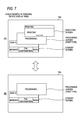
FIG. 7 is a diagram illustrating a second stack example of the screen data storage area; and
FIG. 8 is a diagram illustrating a third stack example of the screen data storage area.
DETAILED DESCRIPTION
<Outline of Service Cooperation System 10>
An outline of a service cooperation system 10 according to an illustrative embodiment of the present invention will be described with reference to FIG. 1. The service cooperation system 10 includes a multifunction peripheral (MFP) 51 and a web server 71. The MFP 51 and the web server 71 are connected to each other through the Internet 70.
The web server 71 executes communication with other terminals connected to the Internet, based on HTTP or HTTPS, so as to provide predetermined services to other terminals. An example of the services provided by the web server 71 includes an electric-file storing service. The electric-file storing service is a service in which it is enabled to store electric files in a database provided on the network by a service provider. Examples of the electric-file storing service include a Picasa (a registered trademark) web album, and flickr (a registered trademark).
In a service provided by the web server 71, the web server 71 may issue a server execution instruction or a server display instruction to the MFP 51. The contents of the server execution instruction or the server display instruction will be described below.
<Configuration of MFP 51>
A configuration of the MFP 51 will be described. The MFP 51 includes a printer 19, a scanner 20, a CPU 32, a storage unit 33, a LAN transmission/reception unit 36, a button input unit 38, a panel 39, a modem 40, and a telephone line connection unit 41. These components are communicably connected to each other through an input/output port 43.
The CPU 32 controls each function in accordance with a program stored in the storage unit 33, various signals transmitted and received through the LAN transmission/reception unit 36, and the like. The storage unit 33 may include a random access memory (RAM), a read only memory (ROM), a flash memory, a hard disk (HDD), and the like.
The LAN transmission/reception unit 36 transmits and receives digital signals configuring various kinds of data to and from the web server 71 through the Internet 70. The button input unit 38 is keys for executing each function of the MFP 51. The button input unit 38 may be integrated with a panel 39 as a touch panel. The panel 39 displays various kinds of function information of the MFP 51.
The printer 19 is a device configured to execute printing upon receiving an internal execution instruction for executing printing. The scanner 20 is a device configured to execute reading upon receiving an internal execution instruction for executing reading. The internal execution instructions are output from the button input unit 38, a telephone network 100, a personal computer (not shown) connected to the MFP 51, a built-in timer (not shown) of the MFP 51, and the like. The modem 40 modulates document data to be transmitted by a facsimile function into a signal capable of being transmitted in the telephone network 100 and transmits the modulated signal through the telephone line connection unit 41, and receives a signal input from the telephone network 100 through the telephone line connection unit 41 and demodulates the input signal into document data.
The storage unit 33 includes a screen data storage area 33 a, an image data storage table TB11, and a program 21. The screen data storage area 33 a is an area where various kinds of screen data are stored in a stack data structure. The stack data structure is a data structure having a feature that the last input data is the first output. When data is input, new data is stacked at the top. When the data is output, the data stacked at the top is firstly output. This last-in first-out data input/output type is called Last In First Out (LIFO).
Contents stored in the screen data storage area 33 a are updated by pushing and popping which are two types of basic operation. The CPU 32 can access only image data at the top of the screen data storage area 33 a, and cannot access the other image data. If new image data is stacked (pushed), the new image data becomes the top of the stack, so that the CPU 32 cannot access the image data under the top. If image data is removed (popped) from the stack, the second image data becomes the top of the stack.
The CPU 32 reads screen data stacked at the top of the screen data storage area 33 a, and displays a screen on the panel 39 based on the read screen data. Screen display on the panel 39 may be controlled by, as a trigger, reception of a server display instruction from the web server 71, reception of an internal execution instruction, and the like.
FIG. 5 shows an example of the image data storage table TB 11. The image data storage table TB 11 stores screen data 110, screen types 111, and stackable information 112. Specifically, the screen types 111 have six types including a ‘standby screen’, a ‘processing screen (first type)’, a ‘processing screen (second type)’, an ‘executing screen’, a ‘server instruction screen’, and a ‘menu operation screen’. The ‘standby screen’ is a screen displayed when the MFP 51 is in a standby status. The ‘processing screen (first type)’ and the ‘processing screen (second type)’ are screens displayed when the MFP 51 is in communication with the web server 71. The ‘executing screen’ is a screen displayed when the MFP 51 is executing a function such as a printing operation. The ‘server instruction screen’ is a screen displayed according to a display instruction from the web server 71. The ‘menu operation screen’ is a screen displayed by operation of the user on the button input unit 38, or the like.
The screen data 110 is provided in correspondence with each of the screen types 111. The screen data 110 is data for generating screens to be displayed on the panel 39. FIG. 5 shows screen examples of the screen data 110 corresponding to the screen types 111.
The stackable information 112 is a condition representing, on each screen data, which screen data among screen data of the screen types 111 is allowed to be stacked. Specifically, the ‘standby screen’ allows screens of all of the screen types 111 to be stacked thereon. The ‘processing screen (first type)’ allows screens of all of the screen types 111 to be stacked thereon. Therefore, the ‘executing screen’ can be stacked on the ‘processing screen (first type)’. The ‘processing screen (second type)’ allows only the ‘server instruction screen’ to be stacked thereon. Therefore, the ‘executing screen’ cannot be stacked on the ‘processing screen (second type)’. The ‘executing screen’ allows only the ‘menu operation screen’ and the ‘processing screen (second type)’ to be stacked thereon. The ‘server instruction screen’ is considered as a top screen which does not allow screens of any screen types 111 to be stacked thereon. The ‘menu operation screen’ is also considered as a top screen which does not allow screens of any screen types 111 to be stacked thereon.
The storage unit 33 stores the program 21. The CPU 32 executes a process according to the program 21 of the storage unit 33. The program 21 includes a server application 21 a. The server application 21 a is an application for receiving a server execution instruction and a server display instruction from the web server 71 and causing the MFP 51 to execute a function according to the received instruction. The server execution instruction is an instruction for causing the MFP 51 to execute a printing operation using the printer 19, a reading operation using the scanner 20, or the like. The server display instruction is an instruction for causing the MFP 51 to display the ‘server instruction screen’ on the panel 39.
A configuration of the web server 71 will be described. The web server 71 includes a CPU 72, a storage unit 73, and a communication unit 74. The web server 71 is a device providing a function or data of the web server 71 to the MFP 51 on a network. The CPU 72 controls each function. The storage unit 73 stores various kinds of data. The communication unit 74 transmits and receives various kinds of information to and from the MFP 51.
<Operation of MFP 51>
An operation of the MFP 51 according to the present illustrative embodiment will be described with reference to flow charts of FIGS. 2 to 4 and stack examples of FIGS. 6 to 8. The MFP 51 has three display modes of a default device display mode, a server instruction display mode, and a temporal device display mode.
The default device display mode is a mode for displaying a screen on the panel 39 in accordance with an internal execution instruction. In the default device display mode, among the six screen types 111 stored in the image data storage table TB11, three types of the ‘standby screen’, the ‘executing screen’, and the ‘menu operation screen’ can be displayed.
The server instruction display mode is a mode for displaying a screen on the panel 39 in accordance with the server display instruction from the web server 71. In the server instruction display mode, among the six screen types 111 stored in the image data storage table TB11, two types of the ‘processing screen (second type)’ and the ‘server instruction screen’ can be displayed.
The temporal device display mode is a mode of a case where the server execution instruction is received from the web server 71 while the server display instruction is being received from the web server 71. In the temporal device display mode, among the six screen types 111, two types of the ‘processing screen (first type)’ and the ‘executing screen’ can be displayed.
FIG. 2 shows an operation flow in the default device display mode. The flow of FIG. 2 operates for a time period while the MFP 51 is powered on. FIG. 4 shows an operation flow in the server instruction display mode and the temporal device display mode. FIGS. 6 to 8 show stack examples of image data into the screen data storage area 33 a in the server instruction display mode, the temporal device display mode, and the default device display mode, respectively.
In step S11 of FIG. 2, the CPU 32 initializes the screen data storage area 33 a. Therefore, the screen data storage area 33 a becomes a state where no image data is stored. In step S13, the CPU 32 sets screen data of the ‘standby screen’ as an object of a stack pushing process. Then, the CPU 32 reads image data of the ‘standby screen’ from the image data storage table TB 11. In step S15, the CPU 32 executes the stack pushing process on the image data of the ‘standby screen’.
The stack pushing process executed in step S15 will be described with reference to a flow chart of FIG. 3. In step S111, the CPU 32 determines whether any screen data is already stacked in the screen data storage area 33 a. If it is determined that any screen data is not stacked (No in step S111), the stack pushing process proceeds to step S113. In step S113, the CPU 32 stacks image data, which is the object of the stack pushing process, in the screen data storage area 33 a. Then, the stack pushing process ends.
Meanwhile, if image data is stacked in the screen data storage area 33 a (Yes in step S111), the stack pushing process proceeds to step S115. In step S115, the CPU 32 reads the stackable information 112 for image data stacked at the top in the screen data storage area 33 a.
In step S117, the CPU 32 determines whether the image data, which is the object of the current stack pushing process, is allowed to be stacked on the image data currently stacked at the top. This determination is made by checking whether the screen type 111 of the image data, which is the object of the stack pushing process, matches a stackable type as defined in the stackable information 112. If it is determined that the screen type 111 of the image data, which is the object of the stack pushing process, does not match any stackable type of the stackable information 112 (No in step S117), step S119 is skipped, and the stack pushing process proceeds to step S17 (FIG. 2). Therefore, the image data, which is the object of the stack pushing process, is not stacked in the screen data storage area 33 a. On the other hand, if it is determined that the screen type 111 of the image data, which is the object of the stack pushing process, matches a stackable type of the stackable information 112 (Yes in step S117), the stack pushing process proceeds to step S119 where the image data, which is the object of the stack pushing process, is stacked in the screen data storage area 33 a. Then, the stack pushing process ends.
In an example of the present illustrative embodiment, the image data of the ‘standby screen’ is stacked in the screen data storage area 33 a by the stack pushing process of step S15, as shown in (B) of FIG. 8.
Returning to the description of the flow of FIG. 2, in step S17, the CPU 32 reads image data stacked at the top of the screen data storage area 33 a, and displays the image data on the panel 39.
In step S19, the CPU 32 determines whether any trigger for switching a screen which is being displayed on the panel has occurred. Examples of the trigger include start and end of the server application 21 a, reception of a server execution instruction, an operation of a stop key, reception of a server display instruction, reception of an internal execution instruction, and the like. The internal execution instruction is an instruction for executing the printing operation, the reading operation, or the like in the MFP 51 and is input from, for example, a device other than the web server 71 or a built-in timer or button input unit of the MFP 51. If any trigger has not been occurred (No in step S19), the CPU 32 returns to step S19 and stands by, and if a trigger has occurred (Yes in step S19), the CPU 32 proceeds to step S21. In step S21, the CPU 32 determines whether the server application 21 a has started. If the server application 21 a has started (Yes in step S21), the CPU 32 proceeds to step S27, and if the server application 21 a has not started (No in step S21), the CPU 32 proceeds to step S23.
In step S23, the CPU 32 determines whether any server execution instruction has been received from the web server 71. If a server execution instruction has been received (Yes in step S23), the CPU 32 proceeds to step S27, and if any server execution instruction has not been received (No in step S23), the CPU 32 proceeds to step S25.
In step S25, the CPU 32 determines whether any server display instruction has been received from the web server 71. If a server display instruction has been received (Yes in step S25), the CPU 32 proceeds to step S27, and if any server display instruction has not been received (No in step S25), the CPU 32 proceeds to step S29.
In step S29, the CPU 32 determines whether the server application 21 a has ended. If the server application 21 a has ended (Yes in step S29), the CPU 32 returns to step S11, and if the server application 21 a has not ended (No in step S29), the CPU 32 proceeds to step S31.
In step S31, the CPU 32 determines whether the stop key of the panel 39 has been operated by the user. If the stop key has been operated (Yes in step S31), the CPU 32 returns to step S11, and if the stop key has not been operated (No in step S31), the CPU 32 proceeds to step S33.
In step S33, the CPU 32 determines whether it is required to end the display of the current screen on the panel 39. A case where it is required to end the display of the current screen may be a case where screen switch is required, for example, a case where a function according to an internal execution instruction starts or ends or a case where a new internal execution instruction is received. Specifically, in a printing operation, the case where it is required to end the display of the current screen may be a case where it is required switching from a ‘executing screen’ which displays ‘READING PRINT DATA’ when the print data is being read to a ‘executing screen’ which displays ‘PRINTING’ if the operation is switched to printing on a sheet, a case where the printing ends and thus the display of the ‘executing screen’ becomes unnecessary, and the like. If it is not required to end the display of the current screen (No in step S33), step S35 is skipped, and the CPU 32 proceeds to step S37. On the other hand, if it is required to end the display of the current screen (Yes in step S33), the CPU 32 proceeds to step S35 so as to remove the image data of the current screen on the panel 39 from the screen data storage area 33 a (a stack popping process).
In step S37, the CPU 32 determines whether image data attempting to be displayed on the panel 39 exists. Examples of the image data attempting to be displayed include the ‘executing screen’ and the ‘menu operation screen’ which are displayed in the internal execution instructions. If image data attempting to be displayed does not exit (No in step S37), the CPU 32 returns to step S17, and if image data attempting to be displayed exits (Yes in step S37), the CPU 32 proceeds to step S39. In step S39, the CPU 32 sets the image data attempting to be displayed as an object of the stack pushing process. Then, in step S41, the CPU 32 executes the stack pushing process. Contents of the stack pushing process of step S41 are the same as those of the stack pushing process of step S15, and thus the detailed description will be omitted. Next, the CPU 32 returns to step S17.
In the example of the present illustrative embodiment, if the image data to be displayed is the ‘executing screen’, image data of the ‘executing screen’ is stacked in the screen data storage area 33 a by the stack pushing process of step S15. Therefore, the stack state transitions from a state of (B) of FIG. 8 to a state of (A) of FIG. 8. If the image data to be displayed is the ‘menu operation screen’, image data of the ‘menu operation screen’ is stacked in the screen data storage area 33 a by the stack pushing process of step S15. Therefore, the stack state transitions from a state of (B) of FIG. 8 to a state of (C) of FIG. 8.
<Server Instruction Display Process>
A server instruction display process executed in step S27 will be described with reference to FIG. 4. In step S213, the CPU 32 determines whether to switch the default device display mode to the server instruction display mode or the temporal device display mode. If it is determined to switch the default device display mode to the server instruction display mode, the CPU 32 proceeds to step S215. Examples of the case where it is determined to switch the default device display mode to the server instruction display mode include the case where the server application has started (Yes in step S21) and the case where a server display instruction has been received (Yes in step S25).
In step S215, the CPU 32 determines whether the screen type 111 of the image data stacked at the top of the screen data storage area 33 a is the ‘standby screen’. If the image data stacked at the top is not the ‘standby screen’ (No in step S215), the CPU 32 proceeds to step S217 so as to execute a stack popping process (a process of removing the image data stacked at the top of the screen data storage area 33 a). Then, the CPU 32 returns to step S215. If the image data stacked at the top is the ‘standby screen’ (Yes in step S215), the CPU 32 proceeds to step S217. Therefore, the stack popping process can be repeated until the ‘standby screen’ is stacked at the top of the screen data storage area 33 a (for example, the state of (B) of FIG. 8).
In step S219, the CPU 32 stacks the screen data of the ‘processing screen (first type)’ at the top of the screen data storage area 33 a. Therefore, the stack state becomes a state in which the screen data of the ‘processing screen (first type)’ is on the screen data of the ‘standby screen’. The screen data of the ‘processing screen (first type)’ is screen data allowing the screens of all of the screen types 111 to be stacked thereon.
In step S221, the CPU 32 stacks the image data of the ‘processing screen (second type)’ at the top of the screen data storage area 33 a. Therefore, the stack state becomes a state in which screen data of the ‘processing screen (second type)’ is on the screen data of the ‘processing screen (first type)’. In the example of the present illustrative embodiment, it is allowed to transition the stack state of the screen data storage area 33 a from the state shown in (B) of FIG. 8 to a state shown in (B) of FIG. 6 by the processes of steps S215 to S221. The screen data of the ‘processing screen (second type)’ is screen data allowing only the screen data of the ‘server instruction screen’ to be stacked thereon. Therefore, the transition to the server instruction display mode is completed. During a time period of the server instruction display mode, even if it is attempted to display the ‘executing screen’ on the panel 39, since the screen data of the ‘executing screen’ is not allowed to stacked in the screen data storage area 33 a, the ‘executing screen’ is not displayed.
In step S223, the CPU 32 determines whether screen data of the ‘server instruction screen’ to be newly displayed on the panel 39 exists. If screen data of the ‘server instruction screen’ to be newly displayed does not exist (No in step S223), step S225 is skipped and the server instruction display process ends. Then, the CPU 32 returns to step S17 (FIG. 2). On the other hand, if screen data of the ‘server instruction screen’ to be newly displayed exists (Yes in step S223), the CPU 32 proceeds to step S225. In step S225, the CPU 32 executes a stack pushing process on the screen data of the ‘server instruction screen’. Then, the server instruction display process ends, and the CPU 32 returns to step S17 (FIG. 2).
In the example of the present illustrative embodiment, in step S225, if the screen data of the ‘server instruction screen’ is stacked in the screen data storage area 33 a, the stack state transitions from the state shown in (B) of FIG. 6 to a state shown in (A) of FIG. 6.
On the other hand, if it is determined to switch the default device display mode to the temporal device display mode in step S213, the CPU 32 proceeds to step S231. Examples of the case where it is determined to switch the default device display mode to the temporal device display mode include the case where the server execution instruction has been received (Yes in step S23). In step S231, the CPU 32 determines whether the image data stacked at the top is the ‘server instruction screen’. If the image data at the top is the ‘server instruction screen’ (Yes in step S231), the CPU 32 proceeds to step S235 so as to perform a stack popping process, and then returns to step S231. If the image data stacked at the top is not the ‘server instruction screen’ (No in step S231), the CPU 32 determines that the image data of the ‘processing screen (second type)’ is at the top (the state of (B) of FIG. 6), and then proceeds to step S237.
In step S237, the CPU 32 executes a stack popping process. Therefore, the image data of the ‘processing screen (second type)’ is removed from the screen data storage area 33 a. As a result, the stack state becomes a state in which the ‘processing screen (first type)’ is at the top of the screen data storage area 33 a. In the example of the present illustrative embodiment, it is allowed to transition the stack state of the screen data storage area 33 a from the state shown in (B) of FIG. 6 to a state shown in (B) of FIG. 7 by the processes of steps S231 to S237. The screen data of the ‘processing screen (first type)’ is screen data allowing the screens of all of the screen types 111 to be stacked thereon. Accordingly, the transition to the temporal device display mode is completed. During a time period of the temporal device display mode, since the screen data of the ‘executing screen’ is allowed to be stacked in the screen data storage area 33 a, the ‘executing screen’ can be displayed on the panel 39. Therefore, it is allowed to display the ‘executing screen’ according to the server execution instruction.
In step S239, the CPU 32 determines whether screen data of the ‘executing screen’ that needs to be newly displayed on the panel 39 exists. Specifically, if a program controlling the printing operation requests the ‘executing screen’ which displays ‘READING PRINT DATA’ or the ‘executing screen’ which displays ‘PRINTING’ from the server application 21 a, since screen data of the ‘executing screen’ requested to be newly displayed on the panel 39 is prepared, the screen data of the ‘executing screen’ that needs to be newly displayed on the panel 39 exists. If screen data of the ‘executing screen’ to be newly displayed does not exist (No in step S239), step S241 is skipped and the server instruction display process ends. Then, the CPU 32 returns to step S17 (FIG. 2). Meanwhile, if screen data of the ‘executing screen’ to be newly displayed exists (Yes in step S239), the CPU 32 proceeds to step S241. In step S241, the CPU 32 executes a stack pushing process on the screen data of the ‘executing screen’. Then, the server instruction display process ends, and the CPU 32 returns to step S17 (FIG. 2).
In the example of the present illustrative embodiment, in step S241, if the screen data of the ‘executing screen’ is stacked in the screen data storage area 33 a, the stack state transitions from the state shown in (B) of FIG. 7 to a state shown in (A) of FIG. 7.
<Effects>
In the MFP 51 according to the present illustrative embodiment, a screen based on an internal execution instruction acting as a trigger is not displayed during a time period (server instruction display mode) while a screen is being displayed by reception of the server display instruction from the web server 71. Therefore, it is possible to prevent a screen (the ‘server instruction screen’) based on a server display instruction acting as a trigger and a screen (the ‘executing screen’, the ‘menu operation screen’, or the like according to an internal execution instruction) based on an internal execution instruction acting a trigger from being displayed together. Therefore, it becomes easy for the user to recognize whether a displayed screen is based on a server display instruction or not, and thus convenience for the user can be improved.
In a case of employing a mode where the previous ‘server instruction screen’ is kept displayed on the panel 39 in a standby period from when the screen data of the previous ‘server instruction screen’ is received to when the screen data of the next ‘server instruction screen’ is received, the user may erroneously recognize that the MFP 51 freezes due to an error or the like. However, in the MFP 51 according to the present illustrative embodiment, a structure in which the screen data of the ‘server instruction screen’ is stacked on the screen data of the ‘processing screen (second type)’ is formed by the processes of steps S221 to S225. Therefore, in the standby period, it is possible to display the screen during processing on the panel 39 by removing the screen data of the previous ‘server instruction screen’ from the screen data storage area 33 a. Therefore, it is possible to inform the user that the MFP 51 is in communication with the web server 71, and thus it is possible to prevent the erroneous recognition of the user.
If the priorities are assigned for each of the screen types 111 of the screen data, and control is performed such that the screen data with a priority lower than the priority of the screen data stacked at the top of the screen data storage area 33 a is not allowed to be stacked on the screen data stacked at the top, when it is determined whether it is allowed to stack screen data thereon, it is impossible to taking into account a combination in which the screen data are stacked. However, in the MFP 51 according to the present illustrative embodiment, image data itself is associated with the types of screen data which are allowed to be stacked on the image data by the stackable information 112. Therefore, when it is determined in step S117 whether it is allowed to stack screen data in the screen data storage area 33 a, since it is possible to take into account a combination in stacking the screen data, appropriate control becomes possible.
In the MFP 51 according to the present illustrative embodiment, if a server execution instruction is received from the web server 71 during a time period (the server instruction display mode) while a display instruction screen based on a server display instruction is being displayed, in step S237, transition to the temporal device display mode is allowed. In the temporal device display mode, the image data of the ‘processing screen (first type)’ (image data allowing screen data of all of the screen types 111 to be stacked thereon) is stacked at the top of the screen data storage area 33 a. Therefore, even in the time period while the server display instruction is being received, it is possible to stack the screen data of the ‘executing screen’ based on a server execution instruction, in the screen data storage area 33 a. Therefore, it is possible to display the ‘executing screen’ based on the server execution instruction acting as a trigger on the panel 39, and thus convenience for the user can be improved.
In the MFP 51 according to the present illustrative embodiment, it is allowed to stack the screen data of the ‘standby screen’ at the bottom of the screen data storage area 33 a by the processes of steps S11 to S13. Accordingly, for example, if the MFP 51 has started, it is possible to display the ‘standby screen’ on the panel 39. Therefore, it becomes easy for the user to recognize that the MFP 51 is in the standby status, for example, during the start of the MFP 51, and thus convenience for the user can be improved.
While the present invention has been shown and described with reference to certain illustrative embodiments thereof, it will be understood by those skilled in the art that various changes in form and details may be made therein without departing from the spirit and scope of the invention as defined by the appended claims.
<Modifications>
In the above-described illustrative embodiment, in the server instruction display mode, the stack state becomes a state in which the screen data of the ‘processing screen (second type)’ is stacked on the screen data of the ‘processing screen (first type)’ (step S221); however, the present invention is not limited thereto. In the server instruction display mode, the stack state may be a state in which only the ‘processing screen (first type)’ is stacked. Then, in the server instruction display mode, control using a flag or the like may be performed such that it is not allowed to stack the screen data of the ‘executing screen’ in the screen data storage area 33 a.
The screen example of the screen data 110 shown in FIG. 5 is just an example. Screen contents other then the screen shown in FIG. 5 may be used.
The technical elements described in the specification or the drawings can exhibit technical usefulness, either alone or in combination, and combinations are not limited to those described in the claims as filed. The techniques illustrated in the specification or the drawings can achieve a plurality of purposes at the same time, and achieving only one of them has technical usefulness.

Claims (4)

What is claimed is:
1. A communication apparatus comprising:
a first reception unit configured to receive an instruction from a server connected to a network;
a second reception unit configured to receive an instruction from a path other than the server;
a function executing unit configured to execute a function any of when the first reception unit receives a first execution instruction from the server and when the second reception unit receives a second execution instruction from the path other than the server;
a display control unit configured to display a display instruction correspondence screen on a display unit when the first reception unit receives a display instruction from the server, and configured to display an execution correspondence screen on the display unit when the function executing unit executes the function,
wherein during a time period while the display instruction correspondence screen is being displayed, the display control unit displays the execution correspondence screen on the display unit when the first reception unit receives the first execution instruction, but does not display the execution correspondence screen on the display unit when the second reception unit receives the second execution instruction;
a screen data storage unit configured to store display instruction correspondence screen data which is screen data for displaying the display instruction correspondence screen, and execution correspondence screen data which is screen data for displaying the execution correspondence screen; and
a storage control unit configured to control the screen data storage unit to store the screen data in a stack data structure,
wherein the display control unit is configured to display a screen based on screen data stacked at a top of the stack data structure of the screen data storage unit,
the communication apparatus further comprising:
a stackable information storage unit configured to store stackable information representing, on each of the screen data, which screen data is allowed to be stacked; and
an instruction unit,
wherein when a trigger of attempting display of another screen on the display unit occurs, the instruction unit is configured to instruct the storage control unit to stack screen data for displaying the another screen at the top of the stack data structure or instruct the storage control unit to remove screen data stacked at the top of the stack data structure,
wherein the screen data storage unit is configured to further store screen data different from the display instruction correspondence screen data and different from the execution correspondence screen data,
wherein when instructed by the instruction unit and when the stackable information represents that the screen data stacked at the top of the stack data structure allows the screen data for displaying the another screen to be stacked thereon, the storage control unit is configured to execute a process of stacking the screen data for displaying the another screen at the top of the stack data structure,
wherein when instructed by the instruction unit and when the stackable information does not represent that the screen data stacked at the top of the stack data structure allows the screen data for displaying the another screen to be stacked thereon, the storage control unit is configured not to execute the process of stacking the screen data for displaying the another screen at the top of the stack data structure,
wherein the stackable information does not represent that the display instruction correspondence screen data allows the execution correspondence screen data to be stacked thereon,
wherein when the first reception unit receives the display instruction from the server, the instruction unit instructs the storage control unit to stack screen data, for which the stackable information represents that the screen data allows the execution correspondence screen data to be stacked thereon, at the top of the stack data structure, and then instructs the storage control unit to stack the display instruction correspondence screen data at the top of the stack data structure, and
wherein when the first reception unit receives the first execution instruction from the server, the instruction unit instructs the storage control unit to remove the screen data stacked at the top of the stack data structure.
2. The communication apparatus according to claim 1,
wherein the screen data storage unit is configured to further store standby screen data which is screen data for displaying a standby screen, and
wherein the instruction unit instructs the storage control unit to stack the standby screen data at the top of the stack data structure when the communication apparatus is started, or when an instruction to end display of the display instruction correspondence screen is issued.
3. The communication apparatus according to claim 1,
wherein the display instruction correspondence screen data includes:
processing screen data for displaying a screen for informing that processing is being performed, and
server instruction screen data for displaying a screen based on the display instruction received from the server, and
wherein the stackable information represents that the processing screen data allows the server instruction screen data to be stacked thereon.
4. A non-transitory computer-readable medium having a computer program stored thereon and readable by a computer of a communication apparatus, the computer program, when executed by the computer, causing the computer to perform operations comprising:
receiving an instruction from a server connected to a network;
receiving an instruction from a path other than the server;
executing a function in response to any of the following: receiving a first execution instruction from the server and receiving a second execution instruction from the path other than the server;
displaying a display instruction correspondence screen on a display unit when receiving a display instruction from the server, and displaying an execution correspondence screen on the display unit when executing the function,
during a time period while the display instruction correspondence screen is being displayed, displaying the execution correspondence screen on the display unit when receiving the first execution instruction from the server, but not displaying the execution correspondence screen on the display unit when receiving the second execution instruction from the path other than the server;
storing display instruction correspondence screen data which is screen data for displaying the display instruction correspondence screen, and execution correspondence screen data which is screen data for displaying the execution correspondence screen;
controlling the screen data storage unit to store the screen data in a stack data structure;
displaying a screen based on screen data stacked at a top of the stack data structure of the screen data storage unit;
storing stackable information representing, on each of the screen data, which screen data is allowed to be stacked,
wherein when a trigger of attempting display of another screen on the display unit occurs, stacking screen data for displaying the another screen at the top of the stack data structure or removing screen data stacked at the top of the stack data structure,
further storing screen data different from the display instruction correspondence screen data and different from the execution correspondence screen data,
wherein when the stackable information represents that the screen data stacked at the top of the stack data structure allows the screen data for displaying the another screen to be stacked thereon, executing a process of stacking the screen data for displaying the another screen at the top of the stack data structure,
wherein when the stackable information does not represent that the screen data stacked at the top of the stack data structure allows the screen data for displaying the another screen to be stacked thereon, not executing the process of stacking the screen data for displaying the another screen at the top of the stack data structure,
wherein the stackable information does not represent that the display instruction correspondence screen data allows the execution correspondence screen data to be stacked thereon,
wherein when the display instruction is received from the server, stacking screen data, for which the stackable information represents that the screen data allows the execution correspondence screen data to be stacked thereon, at the top of the stack data structure, and then stacking the display instruction correspondence screen data at the top of the stack data structure, and
wherein when the first execution instruction is received from the server, removing the screen data stacked at the top of the stack data structure.
US13/289,922 2010-11-04 2011-11-04 Communication apparatus for displaying a screen using screen data and program of communication apparatus Active 2031-12-02 US8508759B2 (en)

Applications Claiming Priority (2)

Application Number Priority Date Filing Date Title
JP2010-247403 2010-11-04
JP2010247403A JP5527165B2 (en) 2010-11-04 2010-11-04 COMMUNICATION DEVICE AND COMMUNICATION DEVICE PROGRAM

Publications (2)

Publication Number Publication Date
US20120113454A1 US20120113454A1 (en) 2012-05-10
US8508759B2 true US8508759B2 (en) 2013-08-13

Family

ID=46019371

Family Applications (1)

Application Number Title Priority Date Filing Date
US13/289,922 Active 2031-12-02 US8508759B2 (en) 2010-11-04 2011-11-04 Communication apparatus for displaying a screen using screen data and program of communication apparatus

Country Status (3)

Country Link
US (1) US8508759B2 (en)
JP (1) JP5527165B2 (en)
CN (1) CN102457576B (en)

Cited By (3)

* Cited by examiner, † Cited by third party
Publication number Priority date Publication date Assignee Title
US20150363066A1 (en) * 2014-06-12 2015-12-17 Apple Inc. Systems and Methods for Efficiently Navigating Between Applications with Linked Content on an Electronic Device with a Touch-Sensitive Display
US9648062B2 (en) 2014-06-12 2017-05-09 Apple Inc. Systems and methods for multitasking on an electronic device with a touch-sensitive display
US11966578B2 (en) 2018-06-03 2024-04-23 Apple Inc. Devices and methods for integrating video with user interface navigation

Families Citing this family (2)

* Cited by examiner, † Cited by third party
Publication number Priority date Publication date Assignee Title
JP6922200B2 (en) * 2016-12-02 2021-08-18 コニカミノルタ株式会社 Complex device
US10114573B1 (en) * 2017-04-26 2018-10-30 International Business Machines Corporation Dynamic reduction of stack-overflow errors in a recursive data-serialization algorithm

Citations (8)

* Cited by examiner, † Cited by third party
Publication number Priority date Publication date Assignee Title
US20060165456A1 (en) * 2002-11-06 2006-07-27 Shigeki Matsunaga Print system, print device and print instruction method
US20080246989A1 (en) * 2007-04-06 2008-10-09 Shigeo Konuma Image forming apparatus
US20090228813A1 (en) 2008-03-04 2009-09-10 Kiyoshi Sekiguchi Medical control device and its system
US20110083095A1 (en) * 2009-10-06 2011-04-07 Konica Minolta Business Technologies, Inc. Display method, display method of image forming apparatus, display device and image forming apparatus
US20110134453A1 (en) * 2009-12-09 2011-06-09 Sharp Kabushiki Kaisha Multifunction printer and recording medium
US20110242592A1 (en) * 2010-03-30 2011-10-06 Canon Kabushiki Kaisha Image processing apparatus, method of controlling image processing apparatus, and computer readable medium
US20110310429A1 (en) * 2010-06-17 2011-12-22 Canon Kabushiki Kaisha Image processing apparatus, control method of image processing apparatus, and storage medium
US8341541B2 (en) * 2005-01-18 2012-12-25 Microsoft Corporation System and method for visually browsing of open windows

Family Cites Families (3)

* Cited by examiner, † Cited by third party
Publication number Priority date Publication date Assignee Title
JP3633465B2 (en) * 2000-09-27 2005-03-30 日本電気株式会社 Mobile phone terminal and screen transition control method used therefor
JP2004164132A (en) * 2002-11-11 2004-06-10 Nec Corp Multiwindow display device, multiwindow management method for use therewith, and display control program
JP4388073B2 (en) * 2004-10-08 2009-12-24 富士通株式会社 Incoming call notification program, incoming call notification method, and portable terminal device

Patent Citations (9)

* Cited by examiner, † Cited by third party
Publication number Priority date Publication date Assignee Title
US20060165456A1 (en) * 2002-11-06 2006-07-27 Shigeki Matsunaga Print system, print device and print instruction method
US8341541B2 (en) * 2005-01-18 2012-12-25 Microsoft Corporation System and method for visually browsing of open windows
US20080246989A1 (en) * 2007-04-06 2008-10-09 Shigeo Konuma Image forming apparatus
US20090228813A1 (en) 2008-03-04 2009-09-10 Kiyoshi Sekiguchi Medical control device and its system
JP2009207872A (en) 2008-03-04 2009-09-17 Olympus Medical Systems Corp Medical control device and its system
US20110083095A1 (en) * 2009-10-06 2011-04-07 Konica Minolta Business Technologies, Inc. Display method, display method of image forming apparatus, display device and image forming apparatus
US20110134453A1 (en) * 2009-12-09 2011-06-09 Sharp Kabushiki Kaisha Multifunction printer and recording medium
US20110242592A1 (en) * 2010-03-30 2011-10-06 Canon Kabushiki Kaisha Image processing apparatus, method of controlling image processing apparatus, and computer readable medium
US20110310429A1 (en) * 2010-06-17 2011-12-22 Canon Kabushiki Kaisha Image processing apparatus, control method of image processing apparatus, and storage medium

Cited By (12)

* Cited by examiner, † Cited by third party
Publication number Priority date Publication date Assignee Title
US20150363066A1 (en) * 2014-06-12 2015-12-17 Apple Inc. Systems and Methods for Efficiently Navigating Between Applications with Linked Content on an Electronic Device with a Touch-Sensitive Display
US9648062B2 (en) 2014-06-12 2017-05-09 Apple Inc. Systems and methods for multitasking on an electronic device with a touch-sensitive display
US9785340B2 (en) * 2014-06-12 2017-10-10 Apple Inc. Systems and methods for efficiently navigating between applications with linked content on an electronic device with a touch-sensitive display
US20180032228A1 (en) * 2014-06-12 2018-02-01 Apple Inc. Systems and Methods for Efficiently Navigating Between Applications with Linked Content on an Electronic Device with a Touch-Sensitive Display
US10402007B2 (en) 2014-06-12 2019-09-03 Apple Inc. Systems and methods for activating a multi-tasking mode using an application selector that is displayed in response to a swipe gesture on an electronic device with a touch-sensitive display
US10732820B2 (en) * 2014-06-12 2020-08-04 Apple Inc. Systems and methods for efficiently navigating between applications with linked content on an electronic device with a touch-sensitive display
US10795490B2 (en) 2014-06-12 2020-10-06 Apple Inc. Systems and methods for presenting and interacting with a picture-in-picture representation of video content on an electronic device with a touch-sensitive display
US11592923B2 (en) 2014-06-12 2023-02-28 Apple Inc. Systems and methods for resizing applications in a multitasking view on an electronic device with a touch-sensitive display
US12236036B2 (en) 2014-06-12 2025-02-25 Apple Inc. Systems and methods for arranging applications on an electronic device with a touch-sensitive display
US12547267B2 (en) 2014-06-12 2026-02-10 Apple Inc. Systems and methods for resizing applications in a multitasking view on an electronic device with a touch-sensitive display
US11966578B2 (en) 2018-06-03 2024-04-23 Apple Inc. Devices and methods for integrating video with user interface navigation
US12321590B2 (en) 2018-06-03 2025-06-03 Apple Inc. Devices and methods for integrating video with user interface navigation

Also Published As

Publication number Publication date
JP5527165B2 (en) 2014-06-18
CN102457576A (en) 2012-05-16
US20120113454A1 (en) 2012-05-10
JP2012100145A (en) 2012-05-24
CN102457576B (en) 2014-08-06

Similar Documents

Publication Publication Date Title
US8520237B2 (en) Image forming apparatus with print server function, print server activating method in a network, and computer program product
US8508759B2 (en) Communication apparatus for displaying a screen using screen data and program of communication apparatus
US11496634B2 (en) Non-transitory computer-readable medium storing output instructions to control portable terminal and portable terminal
US20120246566A1 (en) Computer readable recording medium, information processing apparatus, and information processing method
GB2529023A (en) Communication apparatus, control method and program
US20140168694A1 (en) Image processing apparatus, method for controlling the same, and storage medium
CN103037135A (en) Image reading apparatus and image reading system
JP2014128899A (en) Printing device
US10091369B2 (en) Image processing system, image processing method, and storage medium
US20130176593A1 (en) Image processing apparatus that performs reproduction synchronization of moving image between the same and mobile information terminal, method of controlling image processing apparatus, storage medium, and image processing system
US20190045069A1 (en) Image processing apparatus, method for controlling the same, storage medium, and image processing system
US10477041B2 (en) Non-transitory recording medium storing instructions for mobile terminal using NFC and mobile terminal using NFC
US20140355060A1 (en) Image forming apparatus, method for controlling image forming apparatus, and storage medium for displaying image information on a preview screen
JP2010165059A (en) Universal printer driver program and recording medium
WO2014019117A1 (en) Booting printer
US20100110494A1 (en) Image forming method and apparatus using portable storage medium
EP1804482A2 (en) Facsimile transmission over a network
US9405999B2 (en) Image forming apparatus
EP2523445B1 (en) Image forming apparatus, method of controlling the same and program
US10477039B2 (en) Non-transitory computer-readable medium storing output instructions to control portable terminal and portable terminal
JP2011100340A (en) Image processing apparatus, method and program for displaying file in the same apparatus
JP6149637B2 (en) Program and information processing apparatus
US9270851B2 (en) Image forming apparatus method and storage medium storing program for controlling display when the image forming appratus returns to an active state from a power-saving state
JP6544163B2 (en) Mobile terminal and program
JP5111325B2 (en) Management device, management system, management method, and computer program

Legal Events

Date Code Title Description
AS Assignment

Owner name: BROTHER KOGYO KABUSHIKI KAISHA, JAPAN

Free format text: ASSIGNMENT OF ASSIGNORS INTEREST;ASSIGNOR:URAKAWA, YUTAKA;REEL/FRAME:027180/0134

Effective date: 20111102

STCF Information on status: patent grant

Free format text: PATENTED CASE

FPAY Fee payment

Year of fee payment: 4

MAFP Maintenance fee payment

Free format text: PAYMENT OF MAINTENANCE FEE, 8TH YEAR, LARGE ENTITY (ORIGINAL EVENT CODE: M1552); ENTITY STATUS OF PATENT OWNER: LARGE ENTITY

Year of fee payment: 8

MAFP Maintenance fee payment

Free format text: PAYMENT OF MAINTENANCE FEE, 12TH YEAR, LARGE ENTITY (ORIGINAL EVENT CODE: M1553); ENTITY STATUS OF PATENT OWNER: LARGE ENTITY

Year of fee payment: 12