US8503774B2 - Apparatus, method and computer readable medium for performing solid-line conversion from lines having breaks - Google Patents
Apparatus, method and computer readable medium for performing solid-line conversion from lines having breaks Download PDFInfo
- Publication number
- US8503774B2 US8503774B2 US12/776,929 US77692910A US8503774B2 US 8503774 B2 US8503774 B2 US 8503774B2 US 77692910 A US77692910 A US 77692910A US 8503774 B2 US8503774 B2 US 8503774B2
- Authority
- US
- United States
- Prior art keywords
- image
- line
- succession
- solid
- module
- Prior art date
- Legal status (The legal status is an assumption and is not a legal conclusion. Google has not performed a legal analysis and makes no representation as to the accuracy of the status listed.)
- Expired - Fee Related, expires
Links
Images


Classifications
-
- G—PHYSICS
- G06—COMPUTING OR CALCULATING; COUNTING
- G06V—IMAGE OR VIDEO RECOGNITION OR UNDERSTANDING
- G06V30/00—Character recognition; Recognising digital ink; Document-oriented image-based pattern recognition
- G06V30/40—Document-oriented image-based pattern recognition
- G06V30/41—Analysis of document content
- G06V30/412—Layout analysis of documents structured with printed lines or input boxes, e.g. business forms or tables
Definitions
- the present invention relates to an image processing apparatus and an image processing program.
- Image processing is performed frequently on a document including tables and the like containing lines having breaks such as dotted lines.
- an image processing apparatus includes an image receiving section, a succession value image generating section and a solid converting section.
- the image receiving section receives an image contains a line having breaks.
- the succession value image generating section generates a succession value image having as a pixel value the number of times of succession of black or white pixels in the image received by the image receiving section.
- the solid-line converting section based on the succession value image generated by the succession value image generating section, performs solid-line conversion in which the line having breaks is changed into a solid line.
- FIG. 1 is a conceptual module configuration diagram for an exemplary configuration according to a first exemplary embodiment
- FIG. 2 is a detailed module configuration diagram for an exemplary configuration according to a first exemplary embodiment
- FIGS. 3A , 3 B and 3 C are explanation diagrams for showing an example of a received image
- FIGS. 4A and 4B are explanation diagrams for showing an example of a white run map image
- FIGS. 5A and 5B are explanation diagrams for showing an example of a property of a white run map image
- FIGS. 6A and 6B are explanation diagrams for showing an example of a property of a white run map image
- FIGS. 7A and 7B are explanation diagrams for showing an example of processing performed by a white run map filtering module V;
- FIG. 8 is an explanation diagram showing an example of processing performed by a logical sum processing module V and the like;
- FIGS. 9A and 9B are explanation diagrams for showing an example of processing performed by a black run map image generating module H and the like;
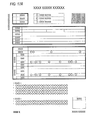
- FIG. 10 is an explanation diagram showing an example of processing performed by a logical sum processing module
- FIG. 11 is an explanation diagram showing an example of processing performed by a reversing module and the like.
- FIG. 12 is an explanation diagram showing an example of processing according to a first exemplary embodiment
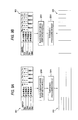
- FIG. 13 is a conceptual module configuration diagram for an exemplary configuration according to a second exemplary embodiment
- FIG. 14 is a detailed module configuration diagram for an exemplary configuration according to a second exemplary embodiment
- FIGS. 15A and 15B are explanation diagrams for showing an example of relation between a black run length and a white run length
- FIGS. 16A and 16B are explanation diagrams for showing an example of processing performed by a black and white run map filtering module V;
- FIGS. 17A and 17B are explanation diagrams for showing an example of processing according to a second exemplary embodiment
- FIG. 18 is a detailed module configuration diagram for an exemplary configuration of a reversing and logical product processing module according to a third exemplary embodiment.
- FIG. 19 is a configuration diagram showing an example of a hardware configuration of a computer for implementing first to third exemplary embodiments.
- FIGS. 3A and 8 examples of various kinds of exemplary embodiments for implementing the present invention are described below with reference to the drawings.
- some figures ( FIGS. 3A and 8 , etc.) contain Japanese characters. Characters in any other languages may be shown in these figures. In other word, these figures show images containing any languages could be applied to the present invention.
- FIG. 1 is a conceptual module configuration diagram for an exemplary configuration according to a first exemplary embodiment.
- module indicates a component of software (a computer program), hardware, or the like which is logically separable from other parts in general.
- a module in the present exemplary embodiment indicates not only a module in a computer program but also a module in a hardware configuration. Accordingly, the present exemplary embodiment serves also as descriptions of a computer program, a system, and a method.
- the expressions “to store” and “to cause something to store” and other equivalent expressions are used. Then, in an exemplary embodiment of a computer program, these expressions indicate “to store into a storage device”, “to perform control such as to cause to store into a storage device”, and the like.
- each module may be in one-to-one correspondence to a function.
- one module may be constructed from a single program.
- a plurality of modules may be constructed from a single program.
- a single module may be constructed from a plurality of programs.
- a plurality of modules may be executed by a single computer.
- a single module may be executed by a plurality of computers in a distributed or parallel computing environment.
- a module may contain another module.
- connection indicates a physical connection as well as a logical connection (data transfer, instructions, and reference relations between data, and the like).
- system and “apparatus” indicate a configuration constructed by connecting a plurality of computers, hardware pieces, apparatuses, and the like through communication means such as a network (including a communication connection of one-to-one correspondence), as well as a configuration implemented by a single computer, hardware piece, apparatus, or the like.
- communication means such as a network (including a communication connection of one-to-one correspondence), as well as a configuration implemented by a single computer, hardware piece, apparatus, or the like.
- system does not include a social “mechanism” (social system) which is based on a human agreement.
- the expression “defined in advance” indicates that something is defined before a processing of interest.
- the image processing apparatus has an image receiving module 110 , a table ruled line correction module 120 , a contact character separating module 130 , a logical sum generating module 140 , and an image output module 150 .
- the image receiving module 110 is connected to the table ruled line correction module 120 and the contact character separating module 130 , and receives an image and then transfers the image to the table ruled line correction module 120 and the contact character separating module 130 .
- the expression “to receive an image” indicates, for example, “to read an image through a scanner, a camera, or the like”, “to receive an image from an external device through a facsimile or the like via a communication line”, and “to read an image stored in a hard disk (one built in a computer or alternatively one connected via a communication line) or the like”.
- the received image is a binary image.
- a multi-valued image including a color image
- binarization is performed. Further, a single image or a plurality of images may be received. Furthermore, as the contents of the image may be a business document, a sheet form, a pamphlet for advertisement, or the like as long as ruled lines constituting a table or the like are contained. Further, the ruled lines may include a line having breaks. Alternatively, a pixel group may be in contact with a ruled line.
- the line having breaks indicates a line other than a solid line, like a dotted line, a dashed line, a dash-dotted line, a double-doted dashed line, and a combination of these.
- a line is generically referred to as a dotted line, hereinafter.
- the pixel group indicates an object that is other than a ruled line and that contains at least a region of four or eight connected pixels.
- the pixel group includes also a set of such pixel regions.
- the set of pixel regions indicates a set such that a plurality of pixel regions in each of which four pixels or the like are connected and that these pixel regions are located in the neighborhood to each other.
- the neighborhood indicates a situation that the pixel regions are located near to each other in terms of physical distance, or alternatively indicates an image region obtained by extracting a character from each line of the text and then projecting them in the horizontal or vertical direction so as to cut out them at a blank position or an image region cut out at intervals defined in advance.
- one pixel group is constructed from the image of one character, in many cases.
- the pixel group need not be a pixel region recognized as an actual character by a person, and may be a part of a character, a pixel region that does not constitute a character, and any other pixel group.
- the ruled line is black in general.
- any white ruled line may be employed, although the following description is given mainly for the case of a black ruled line.
- the table ruled line correction module 120 is connected to the image receiving module 110 , the contact character separating module 130 , and the logical sum generating module 140 , and generates a succession value image having as a pixel value the number of times of succession of black or white pixels in the image received by the image receiving module 110 . Then, based on the generated succession value image, the table ruled line correction module 120 performs solid-line conversion in which a line having breaks is changed into a solid line. Then, the image in which each line having breaks has been converted into a solid line is transferred to the contact character separating module 130 and the logical sum generating module 140 . Alternatively, an image of solid-line converted ruled lines alone may be transferred to the contact character separating module 130 and the like. That is, an image obtained by extracting ruled lines alone (that is, removing pixel groups) from the image received by the image receiving module 110 may be transferred.
- a configuration may be employed that based on comparison with a first threshold value defined in advance, the table ruled line correction module 120 adopts, as two ends, two first pixels extracted from the pixels in the succession value image, and then when a pixel between the first pixels is of a second pixel extracted based on comparison with a second threshold value defined in advance, determines the second pixel to be a break in the line having breaks, so as to perform solid-line conversion.
- a first threshold value defined in advance the table ruled line correction module 120 adopts, as two ends, two first pixels extracted from the pixels in the succession value image, and then when a pixel between the first pixels is of a second pixel extracted based on comparison with a second threshold value defined in advance, determines the second pixel to be a break in the line having breaks, so as to perform solid-line conversion.
- the succession value image indicates an image having, as a pixel value, the number of times of succession (a so-called run length) of pixels of the same color as that of a pixel of interest, in the horizontal or vertical direction.
- each pixel constituting a run length has a pixel value equal to the run length value.
- the pixels within a run length have the same pixel value.
- the succession value image is referred to as a run map image, in some cases.
- Such an image based on the run length of black pixels is referred to as a black run map image, and while an image based on the run length of white pixels is referred to as a white run map image.
- the run map image has the same size (width ⁇ height) as the image received by the image receiving module 110 .
- the image received by the image receiving module 110 is a binary image
- the run map image is a multi-valued image in which each pixel expresses the number of times of succession. For example, 8 bit/pixel may be adopted. In this case, when the number of times of succession is greater than or equal to 256, the pixel value may be fixed to be 255.
- the solid-line conversion indicates that a line having breaks is changed into a solid line. Specifically, a line having breaks is connected (blank parts between short line segments are filled) so that a solid line is generated.
- the contact character separating module 130 is connected to the image receiving module 110 , the table ruled line correction module 120 , and the logical sum generating module 140 . Based on an image generated based on the line generated by solid-line conversion in the table ruled line correction module 120 , the contact character separating module 130 separates a pixel group that is in contact with a solid line or a line having breaks within the image received by the image receiving module 110 . Specifically, for example, an image composed of ruled lines alone undergoes reversing (processing of changing white pixels into black pixels and black pixels into white pixels). Then, the reversed image undergoes contraction.
- the logical sum generating module 140 is connected to the table ruled line correction module 120 , the contact character separating module 130 , and the image output module 150 .
- the logical sum generating module 140 receives: the image composed of ruled lines alone that is generated by solid-line conversion of lines having breaks and obtained from the table ruled line correction module 120 ; and the image composed of objects other than ruled lines that is generated by separating each pixel group in contact with a ruled line and obtained from the contact character separating module 130 . Then, the logical sum generating module 140 performs logical sum operation on these images so as to generates an image in which each line having breaks has been converted into a solid line and each pixel group in contact with a ruled line is separated. Then, the image is transferred to the image output module 150 .
- details of the configuration, the contents of processing, and the like of the logical sum generating module 140 are described later with reference to FIG. 2 and the like.
- the image output module 150 is connected to the logical sum generating module 140 , and receives an image generated by the logical sum generating module 140 and then outputs the image.
- the expression “to output an image” includes “to print data through a printing apparatus such as a printer”, “to display data onto a display apparatus such as a display device”, “to transmit an image through an image transmitting apparatus such as a facsimile machine”, “to write an image into an image storage device such as an image database”, “to store data into a storage medium such as a memory card”, and “to transfer data to another information processing apparatus”. Further, the image output module 150 may output an image to an optical character reader, and then the optical character reader may recognize and convert the image into a document in XML (eXtensible Markup Language) or the like.
- XML eXtensible Markup Language
- FIG. 2 is a detailed module configuration diagram for an exemplary configuration according to the first exemplary embodiment.
- the image receiving module 110 is connected to the white run map image generating module 222 H, the logical sum processing module 224 H, the white run map image generating module 222 V, the logical sum processing module 224 V, and the logical product processing module 233 .
- An example of a received image is the received image 300 illustrated in FIG. 3A .
- contact occurring regions 311 and 312 arise where a character and a ruled line are in contact with each other (see FIG. 3B ).
- a ruled line other than a solid line 321 may be a dotted line 322 , a dashed line 323 , a dash-dotted line 324 , or the like (see FIG. 3C ).
- the table ruled line correction module 120 has a horizontal processing module 221 H, a vertical processing module 221 V, and a logical sum processing module 227 .
- the horizontal processing module 221 H has a white run map image generating module 222 H, a white run map filtering module 223 H, a logical sum processing module 224 H, a black run map image generating module 225 H, and a threshold processing module 226 H.
- the vertical processing module 221 V has a white run map image generating module 222 V, a white run map filtering module 223 V, a logical sum processing module 224 V, a black run map image generating module 225 V, and a threshold processing module 226 V.
- the horizontal processing module 221 H performs horizontal processing (the processing of extracting a horizontal ruled line) onto the image received by the image receiving module 110
- the vertical processing module 221 V performs vertical processing (the processing of extracting a vertical ruled line) onto the image received by the image receiving module 110 .
- These modules are different from each other in the point that horizontal and vertical ruled lines are processed respectively. However, when the image is interpreted as being rotated by 90 degrees, these modules perform conceptually the same processing. Thus, these modules respectively have corresponding sub-modules. The following description is given for any one of these modules or alternatively for a situation of unification of these.
- the white run map image generating module 222 is connected to the image receiving module 110 and the white run map filtering module 223 , and generates a white run map image based on the image received from the image receiving module 110 . Then, the generated white run map image is transferred to the white run map filtering module 223 .
- a white pixel in the image is specified as a pixel of interest. Then, the run length of each white pixel (the number of horizontally successive white pixels in the case of processing by the white run map image generating module 222 H, and the number of vertically successive white pixels in the processing by the white run map image generating module 222 V) is counted. Then, the run length value is imparted as the pixel value to each white pixel belonging to the run length. More specifically, when the run length value of a particular group of white pixels is 10, the pixel value of each of the ten white pixels belonging to the group is set to be 10.
- FIGS. 4A and 4B are explanation diagrams for showing an example of a white run map image.
- the white run map image 410 illustrated in FIG. 4A is one generated by the white run map image generating module 222 H, while the white run map image 420 illustrated in FIG. 4B is one generated by the white run map image generating module 222 V.
- a darker pixel having a greater white run length value that is, a longer white run length is shown darker.
- the run length value exceeding 255 is truncated into 255.
- the white run map filtering module 223 is connected to the white run map image generating module 222 and the logical sum processing module 224 , and performs filtering on the white run map image received from the white run map image generating module 222 . Then, the result of filtering processing is transferred to the logical sum processing module 224 .
- the example of a white run map image shown in FIG. 53 is obtained by the white run map image generating module 222 V processing the character image illustrated in FIG. 5A .
- the example of a white run map image shown in FIG. 6B is obtained by the white run map image generating module 222 V processing the dotted line image illustrated in FIG. 6A .
- a character pixel adjacent region has relatively short white run pixels in many cases, while a dotted line adjacent region has relatively long white run length pixels, in many cases.
- the white run map filtering module 223 utilizes this property.
- FIGS. 7A and 7B are explanation diagrams for showing an example of processing performed by the white run map filtering module 223 V.
- the image illustrated in FIG. 7A is an image of a dotted line that has a two-pixel width and alternates black and white at two-pixel intervals. This image has the following properties.
- White pixels that constitute the dotted line are short.
- white pixels squares shaded with lines inclined from the upper left to the lower right, like the pixel 702 ) located between black pixels (such as the pixel 703 ) constituting the dotted line constitute a short white run length.
- the white run map filtering module 223 V detects white pixels constituting the dotted line. That is, for the white run map image, among the pixels within the filter 710 , pixels B having a short white run length located between pixels A having a long white run length are outputted as black pixels (ON). Other pixels are outputted as white pixels (OFF).
- the pixel A having a long white run length indicates a pixel having a pixel value greater than a threshold value (Th_w) defined in advance.
- the pixel B having a short white run length indicates a pixel having a pixel value is smaller than a threshold value (Th_s) defined in advance.
- the white run map filtering module 223 H also performs similar filtering processing by using a vertical 1 ⁇ 9-pixel filter.
- the size of the filter may be variable in accordance with the width of a dotted line to be detected.
- the above-mentioned 9 ⁇ 1-pixel filter can detect a dotted line of up to seven pixels.
- the logical sum processing module 224 is connected to the image receiving module 110 , the white run map filtering module 223 , and the black run map image generating module 225 .
- the logical sum processing module 224 performs logical sum processing between the image received from the image receiving module 110 and the white run map image received from the white run map filtering module 223 , so as to generate an image in which each dotted line has been converted into a solid line. Then, the generated image is transferred to the black run map image generating module 225 .
- FIG. 8 is an explanation diagram showing an example of processing performed by the logical sum processing module 224 V and the like.
- the received image 300 is an image received by the image receiving module 110 , and has a dotted line, a dashed line, and a dash-dotted line in the regions 811 , 812 , and 813 , respectively.
- the white run map image 420 is a white run map image generated by the white run map image generating module 222 V. From this the white run map image 420 , the white run map filtering module 223 V generates a binary image in which white pixels constituting a dotted line are set ON and the other pixels are ser OFF.
- the solid-line converted image (vertical) 800 is an image generated by the logical sum processing module 224 V, in which the dotted line and the like in the regions 821 , 822 , and 823 corresponding to the regions 811 , 812 , and 813 have been converted into solid lines.
- the black run map image generating module 225 is connected to the logical sum processing module 224 and the threshold processing module 226 , and generates a black run map image based on the image (in which each dotted line has been converted into a solid line) received from the logical sum processing module 224 . Then, the generated black run map image is transferred to the threshold processing module 226 .
- the generation of the black run map image is similar to the generation of the white run map image by the white run map image generating module 222 . That is, a black pixel in the image is specified as a pixel of interest.
- the run length of each black pixel (the number of horizontally successive black pixels in the case of processing by the black run map image generating module 225 H, and the number of vertically successive black pixels in the processing by the black run map image generating module 225 V) is counted. Then, the run length value is imparted as the pixel value to each black pixel belonging to the run length.
- the threshold processing module 226 is connected to the black run map image generating module 225 and the logical sum processing module 227 , and performs threshold processing onto each pixel in the black run map image received from the black run map image generating module 225 . Then, the image having undergone the threshold processing is transferred to the logical sum processing module 227 .
- the threshold processing the pixel value of each pixel is compared with a threshold defined in advance, and then pixels having a value greater than or equal to a threshold defined in advance are extracted as pixels constituting a ruled line. As a result, a ruled line having a value greater than or equal to the threshold remains, while a ruled line having a value smaller than the threshold is removed.
- FIGS. 9A and 9B are explanation diagrams for showing an example of processing performed by the black run map image generating module 225 and the threshold processing module 226 .
- the solid-line converted image (horizontal) 900 illustrated in FIG. 9A is an output image from the logical sum processing module 224 H. Then, as a result of processing performed on the solid-line converted image (horizontal) 900 by the black run map image generating module 225 H and the threshold processing module 226 H, a horizontal ruled line image 910 is obtained. As such, from an image in which each horizontal dotted line has been converted into a solid line, horizontal ruled lines having a value greater than or equal to a threshold are extracted solely.
- the logical sum processing module 227 is connected to the threshold processing module 226 H, the threshold processing module 226 V, the reversing module 231 , and the logical sum processing module 241 .
- the logical sum processing module 227 receives from the threshold processing module 226 H the image composed of horizontal ruled lines alone, then receives from the threshold processing module 226 V the image composed of vertical ruled lines alone, and then generates the logical sum of the two images. Then, the image obtained by the logical sum operation is transferred to the reversing module 231 and the logical sum processing module 241 .
- FIG. 10 is an explanation diagram showing an example of processing performed by the logical sum processing module 227 .
- the logical sum processing module 227 receives the horizontal ruled line image 910 from the threshold processing module 226 H and the vertical ruled line image 920 from the threshold processing module 226 V, and then generates the logical sum of the two images so as to obtain a ruled line image 1000 .
- the contact character separating module 130 has the reversing module 231 , the contraction processing module 232 , and the logical product processing module 233 .
- the reversing module 231 is connected to the logical sum processing module 227 and the contraction processing module 232 , and receives the image composed of ruled lines alone from the logical sum processing module 227 and then performs reversing processing (logical negation processing). Then, the reversed image is transferred to the contraction processing module 232 .
- the contraction processing module 232 is connected to the reversing module 231 and the logical product processing module 233 , and receives the reversed image from the reversing module 231 and then performs contraction processing. Then, the contracted image is transferred to the logical product processing module 233 .
- the contraction processing the value of each pixel on the boundary of a black area is converted into the value of a white pixel of background component so that the black area is contracted by one or more pixels.
- a logical product may be generated between the original image and an image obtained by shifting the original image by one pixel.
- any conventionally known contraction processing may be employed. As a result, an image used for separating a character in contact with a ruled line is obtained.
- the logical product processing module 233 is connected to the image receiving module 110 , the contraction processing module 232 , and the logical sum processing module 241 , and receives the image from the image receiving module 110 and the contracted image from the contraction processing module 232 , and then generates their logical product. Then, the image obtained by the logical product processing is transferred to the logical sum processing module 241 . As a result, an image composed of characters alone other than a ruled line is obtained. Further, in each character having had been in contact with a ruled line, the contact part is removed.
- the logical sum generating module 140 has the logical sum processing module 241 .
- the logical sum processing module 241 is connected to the logical sum processing module 227 , the logical product processing module 233 , and the image output module 150 , and receives from the logical sum processing module 227 the image (containing ruled lines alone) obtained by logical sum processing, receives from the logical product processing module 233 the image (containing characters alone) obtained by logical product processing, and then generates their logical sum. Then, the image obtained by the logical sum processing is transferred to the image output module 150 .
- FIG. 11 is an explanation diagram showing an example of processing per formed by the reversing module 231 , the contraction processing module 232 , the logical product processing module 233 , and the logical sum processing module 241 .
- the reversing module 231 performs reversing processing onto ruled line image 1000 so as to generate a reversed image 1010 .
- the contraction processing module 232 performs contraction processing onto the reversed image 1010 so as to generate a mask 1020 for contact character separation.
- the logical product processing module 233 generates a logical product between the received image 300 and the mask 1020 for contact character separation so as to generate a character image 1030 .
- the logical sum processing module 241 generates a logical sum between the ruled line image 1000 and the character image 1030 so as to generate an output image 1040 .
- the image output module 150 is connected to the logical sum processing module 241 , and receives from the logical sum processing module 241 the image in which each dotted line has been converted into a solid line and in which each character in contact with a ruled line has been separated. Then, the image output module 150 outputs the image.
- FIG. 12 is an explanation diagram showing an example of processing according to the first exemplary embodiment.
- the received image 300 illustrated in Part (a 1 ) of FIG. 12 is an example of an image received by the image receiving module 110 .
- the region 310 has characters in contact with a ruled line respectively in the contact occurring regions 311 and 312 .
- the region 1210 has a dotted line, a dashed line, and a dash-dotted line.
- the output image 1040 illustrated in Part (a 2 ) of FIG. 12 is an example of an image outputted from the image output module 150 .
- FIG. 13 is a conceptual module configuration diagram for an exemplary configuration according to a second exemplary embodiment.
- the image processing apparatus according to the second exemplary embodiment has an image receiving module 1310 , a dotted-line-into-solid-line conversion module 1320 , a line segment extracting module 1330 , a logical product generating module 1340 , and an image output module 1350 .
- characters are deleted from a received image so that an image composed of ruled lines alone is generated.
- dotted lines are not converted into solid lines in the outputted image.
- This exemplary embodiment is utilized, for example, in a case that a form image (a prototype document before filled with characters) is to be recognized.
- the image receiving module 1310 is connected to the dotted-line-into-solid-line conversion module 1320 and the logical product generating module 1340 .
- the image receiving module 1310 is equivalent to the image receiving module 110 illustrated in FIG. 1 , and transfers the received image to the dotted-line-into-solid-line conversion module 1320 and the logical product generating module 1340 .
- the dotted-line-into-solid-line conversion module 1320 is connected to the image receiving module 1310 and the line segment extracting module 1330 , and converts into a solid line each dotted line in the image received by the image receiving module 1310 . That is, the dotted-line-into-solid-line conversion module 1320 performs processing similar to a first half part of the processing performed by the table ruled line correction module 120 illustrated in FIG. 1 .
- the dotted-line-into-solid-line conversion module 1320 performs processing similar to a first half part of the processing performed by the table ruled line correction module 120 illustrated in FIG. 1 .
- details of the configuration, the contents of processing, and the like of the dotted-line-into-solid-line conversion module 1320 are described later with reference to FIG. 14 and the like.
- the line segment extracting module 1330 is connected to the dotted-line-into-solid-line conversion module 1320 and the logical product generating module 1340 , and extracts a line segment serving as a ruled line from the solid-line converted image obtained by the dotted-line-into-solid-line conversion module 1320 . Then, the image composed of ruled lines alone is transferred to the logical product generating module 1340 .
- a white run map image and a black run map image are generated. Then, based on the white run map image and the black run map image having been generated, a line segment is extracted from the image received by the image receiving module 1310 .
- the line segment extracting module 1330 details of the configuration, the contents of processing, and the like of the line segment extracting module 1330 are described later with reference to FIG. 14 and the like.
- the logical product generating module 1340 is connected to the image receiving module 1310 , the line segment extracting module 1330 , and the image output module 1350 , and generates a logical product between the image composed of ruled lines alone generated by the line segment extracting module 1330 and the image received by the image receiving module 1310 so as to delete characters from the document and hence obtain an image composed of ruled lines alone.
- details of the configuration, the contents of processing, and the like of the logical product generating module 1340 are described later with reference to FIG. 14 and the like.
- the image output module 1350 is connected to the logical product generating module 1340 .
- the image output module 1350 is equivalent to the image output module 150 illustrated in FIG. 1 , and outputs the image received from the logical product generating module 1340 .
- the image may be outputted to a form recognition processing apparatus, and then the form recognition processing apparatus may recognize the image and then perform processing in accordance with the type of the form.
- the image may be outputted to a table analysis processing apparatus, and then the table analysis processing apparatus may perform analysis processing of the table constructed from ruled lines.
- FIG. 14 is a detailed module configuration diagram for an exemplary configuration according to the second exemplary embodiment.
- the image receiving module 1310 is connected to the white run map image generating module 1421 H, the logical sum processing module 1423 H, the white run map image generating module 1421 V, the logical sum processing module 1423 V, and the logical product processing module 1441 .
- the image receiving module 1310 is equivalent to the image receiving module 110 illustrated in FIG. 2 .
- the dotted-line-into-solid-line conversion module 1320 is divided into a horizontal processing module 1400 H and a vertical processing module 1400 V.
- the horizontal processing module 1400 H in the dotted-line-into-solid-line conversion module 1320 has a white run map image generating module 1421 H, a white run map filtering module 1422 H, and a logical sum processing module 1423 H.
- the vertical processing module 1400 V in the dotted-line-into-solid-line conversion module 1320 has a white run map image generating module 1421 V, a white run map filtering module 1422 V, and a logical sum processing module 1423 V.
- the line segment extracting module 1330 has a logical sum processing module 1434 .
- the other modules are divided into those for the horizontal processing module 1400 H and the vertical processing module 1400 V.
- the horizontal processing module 1400 H in the line segment extracting module 1330 has a white run map image generating module 1431 H, a black run map filtering module 1432 H, and a black and white run map filtering module 1433 H.
- the vertical processing module 1400 V in the line segment extracting module 1330 has a white run map image generating module 1431 V, a black run map filtering module 1432 V, and a black and white run map filtering module 1433 V.
- the horizontal processing module 1400 H and the vertical processing module 1400 V are different from each other in the point that horizontal and vertical ruled lines are processed respectively. However, these modules perform conceptually the same processing when the image is interpreted as being rotated by 90 degrees. Thus, equivalent corresponding sub-modules are employed. The following description is given for any one of these modules or alternatively for a situation of unification of these.
- the white run map image generating module 1421 , the white run map filtering module 1422 , and the logical sum processing module 1423 in the dotted-line-into-solid-line conversion module 1320 are equivalent respectively to the white run map image generating module 222 , the white run map filtering module 223 , and the logical sum processing module 224 illustrated in FIG. 2 .
- the white run map image generating module 1431 is connected to the logical sum processing module 1423 and the black and white run map filtering module 1433 , and generates a white run map image based on the image (in which each dotted line has been converted into a solid line) received from the logical sum processing module 1423 . Then, the generated white run map image is transferred to the black and white run map filtering module 1433 .
- the black run map image generating module 1432 is connected to the logical sum processing module 1423 and the black and white run map filtering module 1433 , and generates a black run map image based on the image (in which each dotted line has been converted into a solid line) received from the logical sum processing module 1423 . Then, the generated black run map image is transferred to the black and white run map filtering module 1433 .
- the black and white run map filtering module 1433 is connected to the white run map image generating module 1431 , the black run map image generating module 1432 , and the logical sum processing module 1434 . Based on the white run map image received from the white run map image generating module 1431 and the black run map image received from the black run map image generating module 1432 , the black and white run map filtering module 1433 extracts a ruled line.
- FIGS. 15A and 15B are explanation diagrams for showing an example of relation between a black run length and a white run length. As illustrated in FIG. 15B , the white run length values of the adjacent regions 1560 and 1570 in the character image 1550 are shorter than the white run length values of the adjacent regions 1520 and 1530 in the straight line image 1510 illustrated in FIG. 15A .
- FIGS. 16A and 16B are explanation diagrams for showing an example of processing performed by the black and white run map filtering module 1433 V. Based on the white run map image received from the white run map image generating module 1431 V and the black run map image received from the black run map image generating module 1432 V, the black and white run map filtering module 1433 V performs filtering.
- a pixel of interest is outputted as a blackpixel (ON). Otherwise, the pixel of interest is outputted as a white pixel (OFF).
- the pixel of interest located in the center of the horizontal 9 ⁇ 1-pixel filter (the filter 1610 or 1620 illustrated in FIG. 16A or 16 B) is a black pixel.
- the black run length value in the pixel of interest is greater than or equal to a threshold (TH_AV) defined in advance.
- the white run length value of any one of the four pixels on the right-hand side of the pixel of interest is greater than or equal to a threshold (TH_BV) defined in advance.
- the conditions in the processing performed by the black and white run map filtering module 1433 H are similar to the four conditions described above. That is, when the following four conditions are satisfied, a pixel of interest is outputted as a black pixel (ON). Otherwise, the pixel of interest is outputted as a white pixel (OFF).
- the pixel of interest located in the center of the vertical 1 ⁇ 9-pixel filter is a black pixel.
- the black run length value in the pixel of interest is greater than or equal to a threshold (TH_AH) defined in advance.
- the white run length value of any one of the four pixels on the upper side of the pixel of interest is greater than or equal to a threshold (TH_BH) defined in advance.
- the white run length value of any one of the four pixels on the lower side of the pixel of interest is greater than or equal to a threshold (TH_CH) defined in advance.
- both the white run map image and the black run map image are referred to.
- the values TH_AV, TH_BV, TH_CV, TH_AH, TH_BH, and TH_CH may be different from each other. Alternatively, some of them may be the same.
- the size of the filter may be variable in accordance with the width of a dotted line to be detected.
- the black and white run map filtering module 1434 is connected to the black and white run map filtering module 1433 H, the black and white run map filtering module 1433 V, and the logical product processing module 1441 .
- the black and white run map filtering module 1434 generates a logical sum between the image in which horizontal ruled lines alone have been extracted and which is obtained from the black and white run map filtering module 1433 H and the image in which vertical ruled lines alone have been extracted and which is obtained from the black and white run map filtering module 1433 V, such as to generates an image composed of ruled lines alone in which dotted lines have been converted into solid lines. Then, the generated image is transferred to the logical product processing module 1441 .
- the logical product processing module 1441 is connected to the image receiving module 1310 , the logical sum processing module 1434 , and the image output module 1350 .
- the logical product processing module 1441 generates a logical product between the image composed of ruled lines alone in which dotted lines have been converted into solid lines and which is obtained from the logical sum processing module 1434 and the image obtained from the image receiving module 1310 , so as to generate an image composed of ruled lines alone containing dotted lines. Then, the generated image is transferred to the image output module 1350 .
- FIGS. 17A and 17B are explanation diagrams for showing an example of processing according to the second exemplary embodiment.
- the received image 1710 is an example of an image received by the image receiving module 1310 , and contains characters, a photographic image, and ruled lines such as dotted lines and solid lines.
- the characters in the received image 1710 in FIG. 17A are represented as symbols “X” or “ ⁇ ”, etc.
- the output image 1720 is obtained as a result of the processing according to the second exemplary embodiment, and is outputted from the image output module 1350 . As such, an image composed of ruled lines alone such as dotted lines and solid lines is obtained.
- FIG. 18 is a detailed module configuration diagram for an exemplary configuration of a reversing and logical product processing module 1840 according to a third exemplary embodiment. This configuration is obtained when the logical product generating module 1340 in the second exemplary embodiment is replaced by the reversing and logical product processing module 1840 .
- like parts to those in the second exemplary embodiment are designated by like numerals. Thus, duplicate description is omitted.
- the reversing and logical product processing module 1840 has a reversing module 1841 and a logical product processing module 1842 .
- the logical product processing module 1842 is connected to the image receiving module 1310 , the reversing module 1841 , and the image output module 1350 .
- the logical product processing module 1842 generates a logical product between the image received from the image receiving module 1310 and the reversed image received from the reversing module 1841 , so as to generate an image composed of characters alone in which ruled lines have been deleted. Then, the image composed of characters alone is transferred to the image output module 1350 .
- the image output module 1350 is connected to the logical product processing module 1842 , and outputs the image received from the logical product processing module 1842 .
- the image may be outputted to an optical character reader, and then the optical character reader may perform character recognition.
- FIG. 19 An example of hardware configuration of the image processing apparatus of the above-mentioned exemplary embodiment is described below with reference to FIG. 19 .
- the configuration shown in FIG. 19 is constructed from a personal computer (PC) or the like.
- This hardware configuration has: a data reading section 1917 such as a scanner; and a data output section 1918 such as a printer.
- the host bus 1904 is connected through the bridge 1905 to the external bus 1906 such as a PCI (Peripheral Component Interconnect/Interface) bus.
- PCI Peripheral Component Interconnect/Interface
- the HDD (Hard Disk Drive) 1911 has a hard disk in the inside, and drives the hard disk so as to record or reproduce programs and information executed by the CPU 1901 .
- the hard disk stores the image received by the image receiving module 110 , the run map image, and the like. Further, various kinds of computer programs, like various kinds of data processing programs other than those described above, are stored.
- the drive 1912 reads out data or a program recorded on the presently-attached removable recording medium 1913 such as a magnetic disk, an optical disk, a magneto-optical disk, and a semiconductor memory. Then, the data or the program is provided to the RAM 1903 connected through the interface 1907 , the external bus 1906 , the bridge 1905 , and the host bus 1904 .
- the removable recording medium 1913 may be used also as a data recording region similarly to the hard disk.
- the connection port 1914 is a port to which an external connection device 1915 is connected, and has connection sections of USB, IEEE 1394, and the like.
- the connection port 1914 is connected to the CPU 1901 and the like through the interface 1907 , the external bus 1906 , the bridge 1905 , the host bus 1904 , and the like.
- the communication section 1916 is connected to the network, and executes data communication with the outside.
- the data reading section 1917 is constructed from a scanner or the like, and executes document reading.
- the data output section 1918 is constructed from a printer or the like, and executes document data output.
- the hardware configuration of the image processing apparatus shown in FIG. 19 is illustrative.
- the present exemplary embodiment is not limited to the configuration shown in FIG. 19 , and may be another one as long as the modules described in the present exemplary embodiment are implemented.
- a part of the modules may be constructed from dedicated hardware (such as an application specific integrated circuit (ASIC)).
- ASIC application specific integrated circuit
- a mode may be employed that a part of the modules are located in an external system and connected through a communication line.
- a plurality of systems like that shown in FIG. 19 may be connected to each other through a communication line, and operate in a cooperative manner.
- the present configuration may be incorporated in a copying machine, a facsimile machine, a scanner, a printer, a combined machine (an image processing apparatus having any two or more functions of a scanner, a printer, a copying machine, a facsimile machine, and the like), or the like.
- the processing has been decreased separately for the horizontal direction and for the vertical direction.
- the image may be processed in a state of being rotated by 90 degrees.
- the processing in the horizontal direction and the processing in the vertical direction may be performed in parallel to each other. Alternatively, they may be performed serially.
- a module in an exemplary embodiment may be incorporated into another exemplary embodiment, or may replace a module in an exemplary embodiment).
- a technique described in the section of background art may be employed as the contents of processing of a module.
- the expressions “greater (longer) than or equal to”, “smaller (shorter) than or equal to”, “greater than (exceeding)”, “smaller than”, and the like may be replaced by “greater (longer) than”, “smaller (shorter) than”, “greater than or equal to”, “smaller than or equal to”, and the like, as long as conflict does not arise in the combination.
- each program described above may be regarded as an invention in a “computer-readable recording medium that carries a program”.
- a “computer-readable recording medium that carries a program” indicates a computer-readable recording medium that carries a program and is used for installation and execution of a program, circulation of a program, or the like.
- employable recording media include: a digital versatile disk (DVD) such as a DVD-R, a DVD-RW, and a DVD-RAM according to the standard set forth by the DVD Forum; a DVD+R, a DVD+RW, and the like set forth by DVD+RW; compact disks (CDs) such as a read-only memory (CD-ROM), a CD recordable (CD-R), and a CD rewritable (CD-RW); a Blu-ray Disc (registered trademark); a magneto-optical disk (MO); a flexible disk (FD); a magnetic tape; a hard disk; a read-only memory (ROM); an electrically erasable and programmable read only memory (EEPROM); a flash memory; and a random access memory (RAM).
- DVD digital versatile disk
- DVD-R digital versatile disk
- DVD-RW digital versatile disk
- DVD+R a DVD+RW
- CD-RW compact disks
- CDs such as a read-only memory
- the programs described above or a part of them may be saved or circulated in the form of being recorded on the recording medium.
- the programs may be transmitted by communication through a transmission medium like a wired network, a wireless communication network, or a combination of these which is used in a local area network (LAN), a metropolitan area network (MAN), a wide area network (WAN), the Internet, an intranet, an extranet, or the like.
- the programs may be transmitted on carrier waves.
- each program described above may be a part of another program, or alternatively may be recorded on a recording medium together with other programs. Further, each program may be divided and recorded on a plurality of recording media. Furthermore, any recording mode such as compression and encryption may be employed as long as reproduction is available.
Landscapes
- Engineering & Computer Science (AREA)
- Computer Vision & Pattern Recognition (AREA)
- Artificial Intelligence (AREA)
- Physics & Mathematics (AREA)
- General Physics & Mathematics (AREA)
- Multimedia (AREA)
- Theoretical Computer Science (AREA)
- Image Analysis (AREA)
- Character Input (AREA)
- Character Discrimination (AREA)
Abstract
Description
Claims (10)
Applications Claiming Priority (2)
| Application Number | Priority Date | Filing Date | Title |
|---|---|---|---|
| JP2009-212684 | 2009-09-15 | ||
| JP2009212684A JP5365440B2 (en) | 2009-09-15 | 2009-09-15 | Image processing apparatus and image processing program |
Publications (2)
| Publication Number | Publication Date |
|---|---|
| US20110064305A1 US20110064305A1 (en) | 2011-03-17 |
| US8503774B2 true US8503774B2 (en) | 2013-08-06 |
Family
ID=43730597
Family Applications (1)
| Application Number | Title | Priority Date | Filing Date |
|---|---|---|---|
| US12/776,929 Expired - Fee Related US8503774B2 (en) | 2009-09-15 | 2010-05-10 | Apparatus, method and computer readable medium for performing solid-line conversion from lines having breaks |
Country Status (2)
| Country | Link |
|---|---|
| US (1) | US8503774B2 (en) |
| JP (1) | JP5365440B2 (en) |
Families Citing this family (5)
| Publication number | Priority date | Publication date | Assignee | Title |
|---|---|---|---|---|
| US9952038B2 (en) * | 2013-03-27 | 2018-04-24 | Nikon Corporation | Shape measurement device, structure production system, shape measurement method, structure production method, and shape measurement program |
| JP6631119B2 (en) * | 2015-09-18 | 2020-01-15 | 富士ゼロックス株式会社 | Image processing device |
| CN109635762A (en) * | 2018-12-18 | 2019-04-16 | 正元地理信息有限责任公司 | A kind of city management method, system and device |
| CN109874051A (en) * | 2019-02-21 | 2019-06-11 | 百度在线网络技术(北京)有限公司 | Video content processing method, device and equipment |
| KR20230062065A (en) * | 2021-10-29 | 2023-05-09 | 삼성에스디에스 주식회사 | Method, apparatus, system and computer program for adjusting table coordinates information |
Citations (9)
| Publication number | Priority date | Publication date | Assignee | Title |
|---|---|---|---|---|
| JPH0512489A (en) | 1991-07-03 | 1993-01-22 | Matsushita Electric Ind Co Ltd | Table recognition device |
| JPH0540847A (en) | 1991-08-05 | 1993-02-19 | Oki Electric Ind Co Ltd | Table ruled line extraction method |
| JPH05174186A (en) | 1991-03-06 | 1993-07-13 | Matsushita Electric Ind Co Ltd | Table recognizing device |
| JPH07230525A (en) | 1993-12-22 | 1995-08-29 | Ricoh Co Ltd | Ruled line recognition method and table processing method |
| JPH1097588A (en) | 1996-09-19 | 1998-04-14 | Ricoh Co Ltd | Ruled line recognition method, table processing method, and recording medium |
| JPH10214310A (en) | 1997-01-30 | 1998-08-11 | Nec Corp | Line segment detector |
| JPH11232382A (en) | 1998-02-10 | 1999-08-27 | Hitachi Ltd | Ruled line extraction method and ruled line removal method |
| JP3140079B2 (en) | 1991-03-19 | 2001-03-05 | 株式会社リコー | Ruled line recognition method and table processing method |
| US20090028388A1 (en) * | 2007-07-24 | 2009-01-29 | Nec Electronics Corporation | On-vehicle image processing apparatus |
Family Cites Families (3)
| Publication number | Priority date | Publication date | Assignee | Title |
|---|---|---|---|---|
| JPH09282414A (en) * | 1996-04-10 | 1997-10-31 | Fujitsu Ltd | Pattern extraction device |
| JP3391987B2 (en) * | 1996-08-06 | 2003-03-31 | 株式会社リコー | Form recognition device |
| JP3180792B2 (en) * | 1999-01-14 | 2001-06-25 | 日本電気株式会社 | Character recognition device, character learning device, and computer-readable recording medium |
-
2009
- 2009-09-15 JP JP2009212684A patent/JP5365440B2/en not_active Expired - Fee Related
-
2010
- 2010-05-10 US US12/776,929 patent/US8503774B2/en not_active Expired - Fee Related
Patent Citations (9)
| Publication number | Priority date | Publication date | Assignee | Title |
|---|---|---|---|---|
| JPH05174186A (en) | 1991-03-06 | 1993-07-13 | Matsushita Electric Ind Co Ltd | Table recognizing device |
| JP3140079B2 (en) | 1991-03-19 | 2001-03-05 | 株式会社リコー | Ruled line recognition method and table processing method |
| JPH0512489A (en) | 1991-07-03 | 1993-01-22 | Matsushita Electric Ind Co Ltd | Table recognition device |
| JPH0540847A (en) | 1991-08-05 | 1993-02-19 | Oki Electric Ind Co Ltd | Table ruled line extraction method |
| JPH07230525A (en) | 1993-12-22 | 1995-08-29 | Ricoh Co Ltd | Ruled line recognition method and table processing method |
| JPH1097588A (en) | 1996-09-19 | 1998-04-14 | Ricoh Co Ltd | Ruled line recognition method, table processing method, and recording medium |
| JPH10214310A (en) | 1997-01-30 | 1998-08-11 | Nec Corp | Line segment detector |
| JPH11232382A (en) | 1998-02-10 | 1999-08-27 | Hitachi Ltd | Ruled line extraction method and ruled line removal method |
| US20090028388A1 (en) * | 2007-07-24 | 2009-01-29 | Nec Electronics Corporation | On-vehicle image processing apparatus |
Also Published As
| Publication number | Publication date |
|---|---|
| JP5365440B2 (en) | 2013-12-11 |
| JP2011065204A (en) | 2011-03-31 |
| US20110064305A1 (en) | 2011-03-17 |
Similar Documents
| Publication | Publication Date | Title |
|---|---|---|
| US10455117B2 (en) | Image processing apparatus, method, and storage medium | |
| US8768052B2 (en) | Image processing apparatus, image processing method, and non-transitory computer readable medium | |
| US8320673B2 (en) | Image processing apparatus, image processing method and computer-readable medium | |
| US8391607B2 (en) | Image processor and computer readable medium | |
| US8201084B2 (en) | Image processing apparatus and computer readable medium | |
| US8503774B2 (en) | Apparatus, method and computer readable medium for performing solid-line conversion from lines having breaks | |
| US8751214B2 (en) | Information processor for translating in accordance with features of an original sentence and features of a translated sentence, information processing method, and computer readable medium | |
| US11283963B2 (en) | Image processing apparatus and image processing method and storage medium | |
| US20170278250A1 (en) | Image processing device, non-transitory computer readable medium, and image processing method | |
| US8977044B2 (en) | Image processing apparatus for area separation of images, image processing method, and computer readable medium | |
| US8805076B2 (en) | Image processing apparatus, image processing method and computer readable medium | |
| US9094556B2 (en) | Image forming apparatus, method for processing image thereof and non-transitory computer-readable recording medium | |
| JP5262778B2 (en) | Image processing apparatus and image processing program | |
| US8620090B2 (en) | Line determination apparatus, line determination method, and computer-readable medium | |
| JP5742283B2 (en) | Image processing apparatus and image processing program | |
| JP6606885B2 (en) | Image processing apparatus and image processing program | |
| US20120249573A1 (en) | Image processing apparatus, image processing method, and computer-readable medium | |
| US11288536B2 (en) | Image processing apparatus, image processing method, and non-transitory computer-readable storage medium | |
| JP5489894B2 (en) | Image processing apparatus and image processing program | |
| JP2012142872A (en) | Image processing apparatus and image processing program | |
| US9704219B2 (en) | Image processing apparatus with improved image reduction processing | |
| JP6481301B2 (en) | Image processing apparatus and image processing program | |
| CN102456139B (en) | Image processing equipment and image processing method | |
| JP4650958B2 (en) | Image processing apparatus, method, and program |
Legal Events
| Date | Code | Title | Description |
|---|---|---|---|
| AS | Assignment |
Owner name: FUJI XEROX CO., LTD., JAPAN Free format text: ASSIGNMENT OF ASSIGNORS INTEREST;ASSIGNORS:UENO, KUNIKAZU;YADA, SHINICHI;REEL/FRAME:024363/0136 Effective date: 20100506 |
|
| STCF | Information on status: patent grant |
Free format text: PATENTED CASE |
|
| FPAY | Fee payment |
Year of fee payment: 4 |
|
| MAFP | Maintenance fee payment |
Free format text: PAYMENT OF MAINTENANCE FEE, 8TH YEAR, LARGE ENTITY (ORIGINAL EVENT CODE: M1552); ENTITY STATUS OF PATENT OWNER: LARGE ENTITY Year of fee payment: 8 |
|
| AS | Assignment |
Owner name: FUJIFILM BUSINESS INNOVATION CORP., JAPAN Free format text: CHANGE OF NAME;ASSIGNOR:FUJI XEROX CO., LTD.;REEL/FRAME:058287/0056 Effective date: 20210401 |
|
| FEPP | Fee payment procedure |
Free format text: MAINTENANCE FEE REMINDER MAILED (ORIGINAL EVENT CODE: REM.); ENTITY STATUS OF PATENT OWNER: LARGE ENTITY |
|
| LAPS | Lapse for failure to pay maintenance fees |
Free format text: PATENT EXPIRED FOR FAILURE TO PAY MAINTENANCE FEES (ORIGINAL EVENT CODE: EXP.); ENTITY STATUS OF PATENT OWNER: LARGE ENTITY |
|
| STCH | Information on status: patent discontinuation |
Free format text: PATENT EXPIRED DUE TO NONPAYMENT OF MAINTENANCE FEES UNDER 37 CFR 1.362 |
|
| FP | Lapsed due to failure to pay maintenance fee |
Effective date: 20250806 |