US8497873B2 - Apparatus and method for correction of projected images - Google Patents
Apparatus and method for correction of projected images Download PDFInfo
- Publication number
- US8497873B2 US8497873B2 US12/550,852 US55085209A US8497873B2 US 8497873 B2 US8497873 B2 US 8497873B2 US 55085209 A US55085209 A US 55085209A US 8497873 B2 US8497873 B2 US 8497873B2
- Authority
- US
- United States
- Prior art keywords
- image
- pixel
- image processing
- interpolation
- processing apparatus
- Prior art date
- Legal status (The legal status is an assumption and is not a legal conclusion. Google has not performed a legal analysis and makes no representation as to the accuracy of the status listed.)
- Expired - Fee Related, expires
Links
Images


Classifications
-
- G—PHYSICS
- G09—EDUCATION; CRYPTOGRAPHY; DISPLAY; ADVERTISING; SEALS
- G09G—ARRANGEMENTS OR CIRCUITS FOR CONTROL OF INDICATING DEVICES USING STATIC MEANS TO PRESENT VARIABLE INFORMATION
- G09G5/00—Control arrangements or circuits for visual indicators common to cathode-ray tube indicators and other visual indicators
- G09G5/36—Control arrangements or circuits for visual indicators common to cathode-ray tube indicators and other visual indicators characterised by the display of a graphic pattern, e.g. using an all-points-addressable [APA] memory
- G09G5/39—Control of the bit-mapped memory
- G09G5/391—Resolution modifying circuits, e.g. variable screen formats
-
- H—ELECTRICITY
- H04—ELECTRIC COMMUNICATION TECHNIQUE
- H04N—PICTORIAL COMMUNICATION, e.g. TELEVISION
- H04N9/00—Details of colour television systems
- H04N9/12—Picture reproducers
- H04N9/31—Projection devices for colour picture display, e.g. using electronic spatial light modulators [ESLM]
- H04N9/3179—Video signal processing therefor
- H04N9/3185—Geometric adjustment, e.g. keystone or convergence
-
- G—PHYSICS
- G09—EDUCATION; CRYPTOGRAPHY; DISPLAY; ADVERTISING; SEALS
- G09G—ARRANGEMENTS OR CIRCUITS FOR CONTROL OF INDICATING DEVICES USING STATIC MEANS TO PRESENT VARIABLE INFORMATION
- G09G2340/00—Aspects of display data processing
- G09G2340/04—Changes in size, position or resolution of an image
- G09G2340/0407—Resolution change, inclusive of the use of different resolutions for different screen areas
-
- G—PHYSICS
- G09—EDUCATION; CRYPTOGRAPHY; DISPLAY; ADVERTISING; SEALS
- G09G—ARRANGEMENTS OR CIRCUITS FOR CONTROL OF INDICATING DEVICES USING STATIC MEANS TO PRESENT VARIABLE INFORMATION
- G09G2340/00—Aspects of display data processing
- G09G2340/04—Changes in size, position or resolution of an image
- G09G2340/0442—Handling or displaying different aspect ratios, or changing the aspect ratio
-
- G—PHYSICS
- G09—EDUCATION; CRYPTOGRAPHY; DISPLAY; ADVERTISING; SEALS
- G09G—ARRANGEMENTS OR CIRCUITS FOR CONTROL OF INDICATING DEVICES USING STATIC MEANS TO PRESENT VARIABLE INFORMATION
- G09G2340/00—Aspects of display data processing
- G09G2340/04—Changes in size, position or resolution of an image
- G09G2340/0492—Change of orientation of the displayed image, e.g. upside-down, mirrored
Definitions
- the present invention relates to an image processing apparatus for outputting a projection image to a display unit in an image display apparatus that projects the projection image onto a projection surface by using an image projecting means having an optical system.
- the image is corrected by electrical signal processing; in a liquid crystal projector apparatus described in Japanese Patent Application Publication No. H8-102900 (in particular, paragraph 0047, FIG. 3), keystone distortion is corrected by linear interpolation between adjacent pixels in the scanning lines of an input video signal.
- the frequency characteristic of the filter selected for interpolation may produce patterns, causing problems of image quality.
- An object of the invention is to solve the problem discussed above.
- An image processing apparatus generates an output image from an input image having pixels arranged in mutually different first and second directions in a matrix, at least part of the input image being enlarged or reduced in the output image,
- the at least part of the input image being enlarged or reduced by determining a pixel value of a pixel assumed to exist at a position in the input image before the enlarging or reducing coordinate transformation, and using the pixel value thus determined as a pixel value of the output image,
- the image processing apparatus comprising:
- an image data storage unit configured to hold the pixel values of the pixels in the input image
- a correction value storage unit configured to hold, as correction values, for each of at least some of the pixels in the output image being used as representative pixels, a difference between the coordinate of the pixel in the first direction and the coordinate in the first direction before the coordinate transformation in the input image, for use in determining the pixel value of said each of the representative pixels;
- a reference pixel position calculation unit configured to determine a position of each pixel in the input image before the coordinate transformation by an interpolation calculation using the correction values for the representative pixels, in order to determine the pixel value of said each pixel in the output image, and output the result as a reference pixel position;
- a decision unit configured to decide, for each pixel in the output image, whether or not the correction values used in the interpolation calculation satisfy a predetermined condition
- an image data reading unit configured to read from the image data storage unit, for each pixel in the output image, the pixel values of a plurality of pixels including said each pixel and pixels positioned in its vicinity, according to values of their reference pixel positions;
- an interpolation coefficient determination unit configured to determine, for said each pixel in the output image, first interpolation coefficients according to a value of its reference pixel position
- an interpolation calculation unit configured to obtaining the pixel value in the output image from the values of said plurality of pixels and the first interpolation coefficients;
- the interpolation coefficient determination unit includes
- an interpolation coefficient calculation unit configured to determine second interpolation coefficients from said value of its reference pixel position and a predetermined function
- an interpolation coefficient switching unit configured to output the second interpolation coefficients or predetermined third interpolation coefficients as the first interpolation coefficients according to the reference pixel position calculated by the reference pixel position calculation unit and the decision by the decision unit.
- the quality of the image can be improved because the interpolation coefficients are modified appropriately in the interpolation coefficient determination unit, according to the output of the decision unit, so that the patterns due to the frequency characteristic of the filter selected for interpolation can be avoided.
- FIG. 1 is a block diagram illustrating the image processing apparatus in a first embodiment of the invention
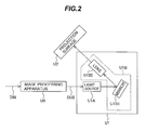
- FIG. 2 is a block diagram illustrating an exemplary structure of a projection television set
- FIGS. 3A and 3B are drawings showing an example of distortion due to an optical system
- FIG. 4 is a drawing illustrating distortion inverse to the distortion shown in FIGS. 3A and 3B ;
- FIG. 5 is a drawing illustrating pixels referred to in a correction for adding the inverse distortion shown in FIG. 4 ;
- FIG. 6 is a drawing illustrating data held in the correction value storage means 2 H;
- FIG. 7 is a drawing showing examples of interpolation coefficients C 6 A(i);
- FIG. 8 is a drawing showing examples of interpolation coefficients C 6 A(i) and C 6 ( i ) used under different conditions;
- FIG. 9 is a drawing illustrating frequency responses RES 1 and RES 2 ;
- FIGS. 10A and 10B are drawings illustrating a defect caused by a difference in frequency responses
- FIG. 11 is a block diagram illustrating an image processing apparatus in a second embodiment of the invention.
- FIGS. 12A and 12B are drawings showing another example of distortion due to an optical system
- FIG. 13 is a drawing illustrating distortion inverse to the distortion shown in FIG. 12B ;
- FIG. 14 is a drawing illustrating pixels referred to in a correction for adding the inverse distortion shown in FIG. 13 ;
- FIG. 15 is a flowchart illustrating the image processing method in a third embodiment
- FIG. 16 is a flowchart illustrating the image processing method in a fourth embodiment.
- FIG. 17 is a block diagram illustrating the image display apparatus in a fifth embodiment.
- FIG. 1 is a drawing illustrating the structure of an image processing apparatus according to the first embodiment of the invention.
- the image processing apparatus U 0 in the drawing has an image data storage means 1 , a correction value storage means 2 H, a reference pixel position calculation means 3 H, a decision means 4 H, an image data reading means 5 H, an interpolation coefficient determination means 6 H, an interpolation calculation means 7 H, and a control means 8 .
- the control means 8 controls the image data storage means 1 , correction value storage means 2 H, reference pixel position calculation means 3 H, decision means 4 H, image data reading means 5 H, interpolation coefficient determination means 6 H, and interpolation calculation means 7 H so that they operate in concert.
- the control signal lines from the control means 8 to the other means are omitted in the drawing.
- the interpolation coefficient determination means 6 H includes an interpolation coefficient calculation means 6 HA and a coefficient switching means 6 HB.
- the image processing apparatus shown in FIG. 1 can be used as part of an image display apparatus, typically a projection display apparatus such as, for example, the rear projection television set shown in FIG. 2 .
- the rear projection television set shown in FIG. 2 comprises the image processing apparatus U 0 shown in FIG. 1 , an image projecting means U 1 , and a projection surface U 2 .
- the image projecting means U 1 includes a light source U 1 A and an optical system U 1 B.
- the optical system U 1 B includes a mirror U 1 B 1 and a lens U 1 B 2 .
- a picture corresponding to an input image DIN is projected onto the projection surface U 2 by the following procedure.
- the image processing apparatus U 0 outputs an image DU 0 on which a process described later has been performed.
- the light source U 1 A outputs light corresponding to the image DU 0 , and the light output from the light source U 1 A is projected onto the projection surface U 2 through the optical system U 1 B including the mirror U 1 B 1 and lens U 1 B 2 .
- FIGS. 3A and 3B are drawings schematically illustrating the distortion.
- a lattice-like image consisting of horizontal lines and vertical lines as shown in FIG. 3A is projected through the optical system U 1 B onto the projection surface U 2 , an image in which the lattice is trapezoidally distorted is displayed.
- the dotted lines PA shown in FIG. 3B indicate the range of the image displayed on the projection surface U 2 when the upper edge of the trapezoidal image is adjusted to match the width of the projection surface.
- an image distorted by the optical system U 1 B in the image projecting means U 1 is projected onto the projection surface U 2 .
- an image DU 0 is generated in which the input image DIN is distorted as shown in FIG. 4 , with characteristics inverse to the distortion caused by the optical system U 1 B (the range of the image DU 0 is indicated by the character PB in FIG. 4 ) and is input to the image projecting means U 1 , the input image DIN is projected on the projection surface U 2 without apparent distortion.
- the input image DIN can be distorted by enlarging or reducing at least part of the input image DIN in the horizontal direction. Such enlargement or reduction can be achieved by performing a coordinate transformation on the input image DIN to obtain the output image DU 0 .
- an image can be generated in which the input image DIN is distorted (distortion-corrected) with characteristics inverse to the distortion caused by the optical system U 1 B, so that the input image DIN can be projected on the projection surface U 2 without apparent distortion.
- the image processing apparatus shown in FIG. 1 performs interpolation and a coordinate transformation on an input image D 0 (corresponding to the input image DIN in FIG. 2 ) to generate and output an output image D 7 (corresponding to the image DU 0 in FIG. 2 ).
- the image data storage means 1 stores the pixel values of the pixels in the input image D 0 .
- the input image D 0 includes pixels arranged in mutually different first and second directions (for example, horizontal and vertical directions) in a matrix; the output image D 7 generated in the image processing apparatus also includes pixels arranged in mutually different first and second directions (for example, horizontal and vertical directions) in a matrix, as in the input image D 0 .
- the pixel positions of the pixels in the input image and output images are expressed by two-dimensional coordinates and the spacing between the pixels in terms of the coordinate values is ‘1’ both in the horizontal and vertical directions.
- the correction value storage means 2 H holds the data relating to pixel positions that need to be referred to (or assumed to exist) to correct the distortion caused by the optical system U 1 B.
- the data relating to the pixel positions that need to be referred to are data representing the coordinates of at least for some of the pixels in the output image before the coordinate transformation for the image enlargement or reduction, for example, data representing relative positions with respect to the pixel positions in the output image, the relative positions being represented specifically by differences between positions. Since the distortion is corrected by performing an enlargement process or a reduction process according to these differences, the differences are also referred to as ‘distortion correction values’.
- FIG. 5 is a drawing illustrating pixel positions that need to be referred to (pixel positions before the coordinate transformation); horizontal coordinates are shown at the top; pixel positions (before the coordinate transformation) in a certain row of the input image D 0 and pixel positions (after the coordinate transformation) in the same row of the output image D 7 are shown below.
- the correction value storage means 2 H holds data representing the relative positions of the reference pixels in image D 0 for some of the pixels in the output image D 7 , specifically, data representing how many pixels to the right or left of the pixel located at the same position in image D 0 the pixel to be referred to is located.
- data representing how many pixels to the right or left of the pixel located at the same position in image D 0 the pixel to be referred to is located.
- the data ‘plus 3’ are held; when it is appropriate to refer to the pixel located four pixels to the left, the data ‘minus 4’ are written; when it is appropriate to refer to the pixel at the same coordinate, the data ‘zero’ are written.
- the difference (a positive or negative signed value) between the horizontal coordinate value of each pixel in the output image D 7 and the horizontal coordinate value of the pixel to be referred in image D 0 (pixel position before the coordinate transformation) is written.
- the distortion correction values of all pixels in the output image D 7 were to be held, a huge number (amount) of data would have to be held, so the data are held at predetermined pixel intervals in both the horizontal and vertical directions. In other words, it is possible to reduce the amount of data to be held by taking pixels at predetermined pixel intervals as representative pixels and holding (data indicating) the distortion correction values only of the representative pixels.
- the pixel values of the pixels to be referred to are obtained by an interpolation calculation. Therefore, the distortion correction values of the representative pixels are not restricted to integers (numbers representing integral multiples of the pixel interval) but may be real numbers including integer parts and fraction parts. If a pixel located 3.5 pixels to the right needs to be referred to, for example, the value ‘plus 3.5’ may be set.
- FIG. 6 shows the distortion correction values P 2 of the representative pixels at the positions of the representative pixels, taking an example in which every 64th pixel in both the horizontal and vertical directions in the output image D 7 is a representative pixel. If M and N are integers, the positions of the representative pixels are expressed by horizontal coordinates of 64 ⁇ M and vertical coordinates of 64 ⁇ N, and the distortion correction values P 2 of the representative pixels are expressed as P 2 (M, N).
- the reference pixel position calculation means 3 H performs linear interpolation for each pixel in the output image D 7 , based on the distortion correction values P 2 (M, N) of the representative pixels held in the correction value storage means 2 H, and calculates, for every pixel in the output image D 7 , the horizontal coordinate U and vertical coordinate V of a pixel position (position before the coordinate transformation) to be referred in the input image D 0 .
- the horizontal coordinate U and vertical coordinate V of the reference pixel position (the pixel position before the coordinate transformation) in the input image D 0 are calculated by the following equation, where J and K are integers greater than or equal to zero and A and B are integers greater than or equal to zero but not exceeding 63.
- the coordinates U, V obtained by equation (1) represent an absolute position in the input image D 0 and are output as reference pixel position data P 3 .
- U Since, from equation (1), U is a real number, it is separated into an integer part and a fraction part.
- the integer part of U (denoted UINT below) and V give the coordinates (UINT, V), which are input to the image data reading means 5 H as data P 3 INT; the fraction part of U (denoted UDEC below) is input to the interpolation coefficient calculation means 6 HA as data P 3 DEC.
- UINT may be defined as the maximum integer not exceeding U and UDEC as the value obtained by subtracting UINT from U.
- the decision means 4 H decides, for each pixel in the output image D 7 , whether the distortion correction values P 2 used in performing the calculation in equation (1) are all zero or not and outputs the result as a flag F 4 .
- the flag F 4 is set to a first value, for example, a value of ‘1’, when P 2 (J, K), P 2 (J+1, K), P 2 (J, K+1), and P 2 (J+1, K+1) are all zero and to a second value, for example, a value of ‘0’, in other cases.
- the image data reading means 5 H outputs, according to the P 3 INT data, the coordinates of a plurality of pixels, including each pixel and pixels positioned in its vicinity, more specifically, the coordinates of four pixels used in the interpolation calculation described later, as data P 5 .
- coordinates (UINT, V) are input as the P 3 INT data
- the coordinates of four points (coordinates indicating the positions of four pixels in the input image D 0 ) expressed as (UINT ⁇ 1, V), (UINT, V), (UINT+1, V), and (UINT+2, V) are output as the P 5 data.
- the image data reading means 5 H reads, according to the P 3 INT data, a plurality of pixels including the pixel at the position indicated by the P 3 INT data and pixels positioned in its vicinity, for example, pixels to its right and left.
- a value indicating black (for example, zero) is output as the pixel value.
- the interpolation coefficient calculation means 6 HA outputs interpolation coefficients C 6 A based on the P 3 DEC data.
- FIG. 7 is a drawing illustrating how the interpolation coefficients C 6 A are determined.
- the interpolation coefficient calculation means 6 HA determines the interpolation coefficients C 6 A, based on a predetermined function f(x) and the P 3 DEC data. If the value of the P 3 DEC data is denoted UDEC, the four values C 6 A( ⁇ 1), C 6 A(0), C 6 A(1), C 6 A(2) are calculated as follows and output as the interpolation coefficients C 6 A.
- FIG. 7 Examples of f(x), f(x ⁇ UDEC), C 6 A( ⁇ 1), C 6 A(0), C 6 A(1), and C 6 A(2) are shown in FIG. 7 .
- the coefficient switching means 6 HB outputs interpolation coefficients C 6 that change according to the values of the data P 3 DEC and the flag F 4 .
- the interpolation coefficients C 6 include four values C 6 ( ⁇ 1), C 6 (0), C 6 (1), and C 6 (2) expressed as follows.
- C 6 B( ⁇ 1), C 6 B(0), C 6 B(1), and C 6 B(2) are predetermined values and are assumed to satisfy the following condition:
- the interpolation calculation means 7 H performs the following interpolation calculation for the pixel at the position represented by coordinates (X, Y) in the output image D 7 , using image data D 1 and a filter expressed by the interpolation coefficients C 6 .
- D 0 ( g, h ) represents the pixel value of the pixel at the position given by coordinates (g, h) in the input image D 0 .
- the pixel value D 7 (X, Y) of the pixel at the position given by the coordinates (X, Y) is thereby obtained.
- the output image D 7 is obtained by performing the above process for all pixels.
- FIG. 8 summarizes the values of the interpolation coefficients C 6 A, C 6 obtained by the image processing apparatus according to the first embodiment.
- FIG. 9 shows the frequency responses of filters with interpolation coefficients obtained from equations (8) and (10) and from equations (9) and (11).
- the frequency response of a filter expressed by interpolation coefficients satisfying the conditions in equations (8) and (10) is unity over the entire frequency band, as shown by RES 1 ;
- the frequency characteristic of a filter expressed by interpolation coefficients satisfying the conditions in equations (9) and (11) has a frequency band less than unity on the high-frequency component side, as shown by RES 2 .
- the noise component oscillating at the high frequency is not removed in regions in which the filter with the interpolation coefficients given by equations (8) and (10) is selected, but is removed in regions in which the filter with the interpolation coefficients given by equations (9) and (11) is selected, because the frequency response in the high-frequency band is less than unity. This results in a partial loss of the signal of the input image DIN, so the brightness of the relevant part of the image is slightly reduced.
- the coefficient switching means 6 HB switches over to select the C 6 B interpolation coefficients for regions in which condition 1 is not satisfied, the interpolation coefficients are changed to coefficients satisfying equation (11) (as a result of which, the use of interpolation coefficients satisfying equation (11) is maintained even in regions not satisfying condition 1), and patterns due to a difference in filter frequency characteristics as described above do not appear.
- an arbitrary distortion can be created in the horizontal direction. That is, the distortion of any optical system can be corrected in the horizontal direction.
- the number of pixels used in the interpolation is not limited to four. If the number of pixels used in the interpolation is n+m+1, a function satisfying the following condition, expressed by a delta function ⁇ (i) and an integer i, for an arbitrary ⁇ (0 ⁇ 1) may be selected:
- the interpolation coefficients C 6 A may be calculated as follows.
- the interpolation coefficients C 6 B only need to satisfy the following condition, expressed by the delta function ⁇ (i) and integer i.
- the delta function is defined as follows.
- the interpolation calculation means 7 H interpolates the pixel value of the output image D 7 as follows:
- every 64th pixel in both the horizontal and vertical directions is a representative pixel and the positions of pixels to be referred to for the representative pixels are stored in the correction value storage means 2 H, but the interval between representative pixels is not limited to 64.
- Tx and Ty are positive integers
- P 2 (M, N) of the representative pixels are stored in the correction value storage means 2 H
- the image processing apparatus it is possible to correct the distortion caused by the optical system U 1 B by taking at least some of pixels in the output image D 7 as representative pixels and, for each representative pixel, writing a positional difference (correction value) between the representative pixel and a pixel to which the representative pixel is referenced in the input image D 0 into the correction value storage means 2 H in order to distort the input image D 0 with characteristics inverse to the distortion caused by the optical system U 1 B, but the data (correction value data) thus written into the correction value storage means 2 H are preferably given values of zero for pixels near the center of the output image D 7 .
- the reason is that since the central vicinity of the image is the part the viewer watches with the greatest attention, it is preferable to display the input image itself in this region instead of displaying an image degraded by an interpolation calculation.
- the pixel values in the input image D 0 are themselves output in a region surrounded by pixels having zero data written in the correction data storage means 2 H (a region satisfying condition 1). Therefore, by setting the data values written into the correction value storage means 2 H to zero for pixels around the center of the output image D 7 , it is possible to display an image having no degradation caused by interpolation calculations in the central vicinity of the image, which people watch with the greatest attention.
- FIG. 11 is a drawing illustrating the structure of an image processing apparatus according to the second embodiment of the invention, which is similar to the structure of the image processing apparatus described in the first embodiment.
- the image processing apparatus of the second embodiment replaces the correction value storage means 2 H, reference pixel position calculation means 3 H, decision means 4 H, image data reading means 5 H, interpolation coefficient determination means 6 H, and interpolation calculation means 7 H in FIG. 1 with a correction value storage means 2 V, a reference pixel position calculation means 3 V, a decision means 4 V, an image data reading means 5 V, an interpolation coefficient determination means 6 V, and an interpolation calculation means 7 V.
- correction value storage means 2 V, reference pixel position calculation means 3 V, decision means 4 V, image data reading means 5 V, interpolation coefficient determination means 6 V, and interpolation calculation means 7 V are similar to the correction value storage means 2 H, reference pixel position calculation means 3 H, decision means 4 H, image data reading means 5 H, interpolation coefficient determination means 6 H, and interpolation calculation means 7 H, respectively, but differ in the content of their processing because, as described later, enlargement and reduction processes are performed in the vertical direction instead of the horizontal direction.
- the image processing apparatus in the second embodiment can also be used as part of an image display apparatus, typically a projection display apparatus such as, for example, the rear projection television set shown in FIG. 2 .
- the image processing apparatus according to the first embodiment produces an arbitrary distortion in the horizontal direction
- the image processing apparatus according to the second embodiment produces an arbitrary distortion in the vertical direction.
- FIGS. 12A and 12B are drawings schematically illustrating an example of distortion in the vertical direction by the optical system U 1 B.
- a lattice-like image consisting of horizontal lines and vertical lines as shown in FIG. 12A is trapezoidally distorted in the vertical direction by the optical system U 1 B as shown in FIG. 12B .
- the dotted line PA shown in FIG. 12B indicates the range of the image displayed on the projection surface U 2 when the left edge of the trapezoidal image is adjusted so as to match the width of the projection surface.
- the image processing apparatus shown in FIG. 11 performs interpolation and a coordinate transformation on an input image D 0 (corresponding to the image DIN in FIG. 2 ) to output an image D 7 (corresponding to the image DU 0 in FIG. 2 ).
- the image data storage means 1 stores the pixel values of the pixels in the input image D 0 .
- the correction value storage means 2 V holds the data (distortion correction value data) of pixel positions that need to be referred to (before the coordinate transformation) to correct the distortion caused by the optical system U 1 B.
- FIG. 14 is a drawing illustrating pixel positions that need to be referred to; vertical coordinates are shown at the left; pixel positions (before the coordinate transformation) in a certain column in the input image D 0 and pixel positions (after the coordinate transformation) in the same column in the output image D 7 are shown to the right.
- the correction value storage means 2 V holds data representing the relative positions of the reference pixels in image D 0 (distortion correction value data) for some of pixels in the output image D 7 , specifically, data representing how many pixels above or below the pixel located at the same position in image D 0 the pixel to be referred to is located.
- data representing how many pixels above or below the pixel located at the same position in image D 0 the pixel to be referred to is located.
- the difference (a positive or negative signed value) between the vertical coordinate value of each pixel in the output image D 7 and the vertical coordinate value of the pixel to be referred to in image D 0 is written.
- the distortion correction values of all pixels in the output image D 7 were to be held, a huge number (amount) of data would have to be held, so the data are held at predetermined pixel intervals in both the horizontal and vertical directions. In other words, it is possible to reduce the amount of data to be held by taking pixels at predetermined pixel intervals as representative pixels and holding the distortion correction values only of the representative pixels.
- the pixel values of the pixels to be referred to are obtained by an interpolation calculation. Therefore, the distortion correction values of the representative pixels are not restricted to integers (numbers representing integral multiples of the pixel interval) but may be real numbers including integer parts and fraction parts. If a pixel located 3.5 pixels below needs to be referred to, for example, the value ‘plus 3.5’ may be set.
- every 64th pixel in both the horizontal and vertical directions is a representative pixel and the distortion correction values P 2 of the representative pixels are held in the correction value storage means 2 V.
- M and N are integers
- the positions of the representative pixels are expressed by horizontal coordinates of 64 ⁇ M and vertical coordinates of 64 ⁇ N
- the distortion correction values P 2 of the representative pixels are expressed as P 2 (M, N), as shown in FIG. 6 .
- the reference pixel position calculation means 3 V performs linear interpolation for each pixel in the output image D 7 , based on the distortion correction values P 2 (M, N) of the representative pixels held in the correction value storage means 2 V, and calculates, for every pixel in the output image D 7 , the horizontal coordinate U and vertical coordinate V of a pixel position (position before the coordinate transformation) to be referred in the input image D 0 .
- the horizontal coordinate U and vertical coordinate V of the reference pixel position (the position before the coordinate transformation) in the input image D 0 are calculated by the following equation, where J and K are integers greater than or equal to zero and A and B are integers greater than or equal to zero but not exceeding 63.
- the coordinates U, V obtained by equation (17) represent an absolute position in the input image D 0 and are output as reference pixel position data P 3 .
- V in equation (17) is a real number, it is separated into an integer part and a fraction part.
- the integer part of V (denoted VINT below) and U give the coordinates (U, VINT), which are input to the image data reading means 5 V as data P 3 INT; the fraction part of V (denoted VDEC below) is input to the interpolation coefficient calculation means 6 VA as data P 3 DEC.
- VINT may be defined as the maximum integer not exceeding V and VDEC as the value obtained by subtracting VINT from V.
- the decision means 4 V operates in the same way as the decision means 4 H in the first embodiment, so a detailed description will be omitted.
- the image data reading means 5 V outputs, according to the P 3 INT data, the coordinates of four pixels as data P 5 , which are used in an interpolation calculation described later.
- coordinates (U, VINT) are input as the P 3 INT data
- the coordinates of four points are output as the P 5 data.
- the image data reading means 5 V reads, according to the P 3 INT data, a plurality of pixels including the pixel at the position indicated by the P 3 INT data and pixels positioned in its vicinity, for example, pixels above and below it.
- a value indicating black (for example, zero) is output as the pixel value.
- the interpolation coefficient calculation means 6 VA operates in the same way as the interpolation coefficient calculation means 6 HA in the first embodiment. More specifically, the interpolation coefficients C 6 A output by the interpolation coefficient calculation means 6 VA are the four values C 6 A( ⁇ 1), C 6 A(0), C 6 A(1), and C 6 A(2) expressed by replacing UDEC in equation (3) with VDEC.
- the coefficient switching means 6 VB operates in the same way as the coefficient switching means 6 HB in the first embodiment, so a detailed description will be omitted.
- the interpolation calculation means 7 V performs the following interpolation calculation for the pixel at the position represented by coordinates (X, Y) in the output image D 7 , using image data D 1 and a filter expressed by the interpolation coefficients C 6 .
- the pixel value D 7 (X, Y) of the pixel at the position given by the coordinates (X, Y) is thereby obtained.
- the output image D 7 is obtained by performing the above process for all pixels.
- the image processing apparatus according to the second embodiment can perform the same processing as the image processing apparatus according to the first embodiment but in the vertical direction, the same effects are obtained in the vertical direction of an image as the effects obtained in the horizontal direction of the image by the image processing apparatus according to the first embodiment.
- FIG. 15 is a flowchart illustrating the image processing method according to the third embodiment of the invention.
- the image processing method of the third embodiment can be used as part of an image display apparatus, a typical example being a projection display apparatus.
- image processing may be executed by the image processing method of the third embodiment in the image processing apparatus U 0 of the rear projection television set shown in FIG. 2 .
- the image processing method shown in FIG. 15 comprises a correction value reading step ST 2 H, a reference pixel position calculation step ST 3 H, a decision step ST 4 H, an image data reading step ST 5 H, an interpolation coefficient determination step ST 6 H, and an interpolation calculation step ST 7 H.
- the interpolation coefficient determination step ST 6 H includes an interpolation coefficient calculation step ST 6 HA and a coefficient switching step ST 6 HB.
- the correction value reading step ST 2 H reads, for representative pixels in the output image D 7 , the distortion correction values P 2 held in the correction value storage means 2 H shown in FIG. 1 .
- the reference pixel position calculation step ST 3 H obtains the values U, V for each pixel in the output image D 7 by performing the calculation in equation (1) on the basis of the distortion correction values P 2 read in the correction value reading step ST 2 H.
- the value U is a real number, so its integer and fraction parts will be denoted UINT and UDEC, respectively.
- the decision step ST 4 H decides, for each pixel in the output image D 7 , whether the distortion correction values P 2 (J, K), P 2 (J+1, K), P 2 (J, K+1), and P 2 (J+1, K+1) used in the calculation in equation (1) are all zero or not and outputs the result as a flag F 4 .
- the flag F 4 is set to a first value, for example, a value of ‘1’, when P 2 (J, K), P 2 (J+1, K), P 2 (J, K+1), and P 2 (J+1, K+1) are all zero and to a second value, for example, a value of ‘0’, in other cases.
- the image data reading step ST 5 H reads the following pixel values in the input image D 0 from the image data storage means 1 in FIG. 1 , based on the values U, V calculated by equation (1), and outputs them: the pixel value D 0 (UINT, V) of the pixel at the position represented by coordinates (UINT, V); the pixel value D 0 (UINT ⁇ 1, V) of the pixel at the position represented by coordinates (UINT ⁇ 1, V); the pixel value D 0 (UINT+1, V) of the pixel at the position represented by coordinates (UINT+1, V); and the pixel value D 0 (UINT+2, V) of the pixel at the position represented by coordinates (UINT+2, V).
- the image data reading step ST 5 H reads, according to the P 3 INT data, a plurality of pixels including the pixel at the position indicated by the P 3 INT data and pixels in its vicinity, for example, pixels to its right and left.
- a value indicating black for example, zero is output as the pixel value.
- the interpolation coefficient calculation step ST 6 HA outputs interpolation coefficients C 6 A obtained by equation (3) on the basis of the UDEC data.
- the method of obtaining the interpolation coefficients C 6 A is the same as in the interpolation coefficient calculation means 6 HA in the first embodiment, so a detailed description will be omitted.
- the coefficient switching step ST 6 HB outputs interpolation coefficients C 6 that change according to the values of the data P 3 DEC and the flag F 4 .
- the interpolation coefficients C 6 are obtained from equation 5.
- the method of obtaining the interpolation coefficients C 6 is the same as in the coefficient switching means 6 HB in the first embodiment, so a detailed description will be omitted.
- the interpolation calculation step ST 7 H performs the following interpolation calculation for the pixel at the position represented by coordinates (X, Y) in the output image D 7 , using pixel values in the input image D 0 and a filter expressed by the interpolation coefficients C 6 .
- the pixel value D 7 (X, Y) of the pixel at the position given by the coordinates (X, Y) is thereby obtained.
- the output image D 7 is obtained by performing the above process for all pixels.
- the image processing method according to the third embodiment can perform the same processing as the image processing apparatus according to the first embodiment, the same effects are obtained as from the image processing apparatus according to the first embodiment.
- the same modifications can also be made as for the image processing apparatus according to the first embodiment. It is also possible to use the output image D 7 obtained in the above processing as the image DU 0 in the image display apparatus shown in FIG. 2 .
- FIG. 16 is a flowchart illustrating the image processing method according to the fourth embodiment of the invention.
- the image processing method of the fourth embodiment can also be used as part of an image display apparatus, a typical example being a projection display apparatus.
- image processing may be executed by the image processing method of the fourth embodiment in the image processing apparatus U 0 of the rear projection television set shown in FIG. 2 .
- the image processing method shown in FIG. 16 comprises a correction value reading step ST 2 V, a reference pixel position calculation step ST 3 V, a decision step ST 4 V, an image data reading step ST 5 V, an interpolation coefficient determination step ST 6 V, and an interpolation calculation step ST 7 V.
- the interpolation coefficient determination step ST 6 V includes an interpolation coefficient calculation step ST 6 VA and a coefficient switching step ST 6 VB.
- the correction value reading step ST 2 V, reference pixel position calculation step ST 3 V, decision step ST 4 V, image data reading step ST 5 V, interpolation coefficient determination step ST 6 V, and interpolation calculation step ST 7 V are similar to the correction value reading step ST 2 H, reference pixel position calculation step ST 3 H, decision step ST 4 H, image data reading step ST 5 H, interpolation coefficient determination step ST 6 H, and interpolation calculation step ST 7 H in the third embodiment, respectively, but differ in the following respect because the enlarging or reducing direction is the vertical direction instead of the horizontal direction.
- the correction value reading step ST 2 V reads, for representative pixels in the output image D 7 , the distortion correction values P 2 held in the correction value storage means 2 V shown in FIG. 11 .
- the reference pixel position calculation step ST 3 V obtains the values U, V for each pixel in the output image D 7 by performing the calculation in equation (17) on the basis of the distortion correction values P 2 read in the correction value reading step ST 2 V.
- the value V is a real number, so its integer and fraction parts will be denoted VINT and VDEC, respectively
- the zero decision step ST 4 V decides, for each pixel in the output image D 7 , whether the distortion correction values P 2 (J, K), P 2 (J+1, K), P 2 (J, K+1), and P 2 (J+1, K+1) used in the calculation in equation (17) are all zero or not and outputs the result as a flag F 4 .
- the flag F 4 is set to a first value, for example, a value of ‘1’, when P 2 (J, K), P 2 (J+1, K), P 2 (J, K+1), and P 2 (J+1, K+1) are all zero and to a second value, for example, a value of ‘0’, in other cases.
- the image data reading step ST 5 V reads the following pixel values in the input image D 0 from the image data storage means 1 in FIG. 11 , based on the values U, V calculated by equation (17), and outputs them: the pixel value D 0 (U, VINT) of the pixel at the position represented by coordinates (U, VINT); the pixel value D 0 (U, VINT ⁇ 1) of the pixel at the position represented by coordinates (U, VINT ⁇ 1); the pixel value D 0 (U, VINT+1) of the pixel at the position represented by coordinates (U, VINT+1); and the pixel value D 0 (U, VINT+2) of the pixel at the position represented by coordinates (U, VINT+2).
- the image data reading step ST 5 V reads, according to the P 3 INT data, a plurality of pixels including the pixel at the position indicated by the P 3 INT data and pixels in its vicinity, for example, pixels above and below it.
- a value indicating black for example, zero is output as the pixel value.
- the interpolation coefficient calculation step ST 6 VA obtains interpolation coefficients C 6 A from the VDEC data.
- the method of obtaining the interpolation coefficients C 6 A is the same as in the interpolation coefficient calculation means 6 VA in the second embodiment, so a detailed description will be omitted.
- the coefficient switching step ST 6 VB outputs interpolation coefficients C 6 that change according to the values of the data P 3 DEC and the flag F 4 .
- the method of obtaining the interpolation coefficients C 6 is the same as in the coefficient switching means 6 VB in the second embodiment, so a detailed description will be omitted.
- the interpolation calculation step ST 7 V performs the following interpolation calculation on the pixel at the position represented by coordinates (X, Y) in the output image D 7 , using pixel values in the input image D 0 and a filter expressed by the interpolation coefficients C 6 .
- the pixel value D 7 (X, Y) of the pixel at the position given by the coordinates (X, Y) is thereby obtained.
- the output image D 7 is obtained by performing the above process for all pixels.
- the image processing method according to the fourth embodiment can perform the same processing as the image processing apparatus according to the second embodiment, the same effects are obtained as from the image processing apparatus according to the second embodiment.
- the same modifications can also be made as for the image processing apparatus according to the second embodiment. It is also possible to use the output image D 7 obtained in the above processing as the image DU 0 in the image display apparatus shown in FIG. 2 .
- FIG. 17 is a block diagram illustrating an image display apparatus according to the fifth embodiment of the invention.
- the image display apparatus shown in FIG. 17 comprises an image processing apparatus UGH, an image processing apparatus U 0 V, an image projecting means U 1 , and a projection surface U 2 .
- the image projecting means U 1 includes a light source U 1 A and an optical system U 1 B, which includes a mirror U 1 B 1 and a lens U 1 B 2 .
- image processing apparatus U 0 H outputs an image DU 0 H generated according to the procedure described in the first embodiment or the third embodiment.
- image processing apparatus U 0 V outputs an image DU 0 V generated according to the procedure described in the second embodiment or the fourth embodiment.
- the light source U 1 A outputs light corresponding to the image DU 0 V, and the light output from the light source U 1 A is projected onto the projection surface U 2 through the optical system U 1 B including the mirror U 1 B 1 and the lens U 1 B 2 .
- image processing apparatus U 0 H corrects the distortion that the optical system U 1 B produces in the horizontal direction and image processing apparatus U 0 V corrects the distortion that the optical system U 1 B produces in the vertical direction. Accordingly, even if the optical system U 1 B produces distortion in both the horizontal and vertical directions, it is possible to display a distortion-free image on the projection surface U 2 .
- the order of arrangement of the image processing apparatus U 0 H and the image processing apparatus U 0 V may be altered. That is, the image processing apparatus U 0 V may be provided to vertically enlarge or reduce the input image, DIN according to the procedure described in the second embodiment, and the image processing apparatus U 0 H may be provided to horizontally enlarge or reduce the image output from the image processing apparatus U 0 V according to the procedure described in the first embodiment.
- the combination of the image processing method described in the third embodiment and the image processing method described in the fourth embodiment may be used. That is, the image display apparatus may be configured to display an image after carrying out enlargement or reduction by the image processing method described in the third embodiment, and enlargement or reduction by the image processing method described in the fourth embodiment, one after another.
- the invention is not limited to this case; it is also applicable when the frequency response RES 2 of the linear filter expressed by the third interpolation coefficients is less than unity in at least some part of the frequency region.
- the first and third embodiments have described a case in which an image is enlarged or reduced in the horizontal direction
- the second and fourth embodiments have described a case in which an image is enlarged or reduced in the vertical direction
- the invention does not limit the enlargement or reduction method to one of the horizontal and vertical directions; it is also applicable to cases in which, from the input image D 0 having pixels arranged in mutually different first and second directions in a matrix, at least part of the input image is enlarged or reduced in a first direction to generate the output image D 7 .
- the characters Q, S, Ts indicating the values of coordinates and the like in the first direction can be used in place of the characters U, X, Tx indicating the values of coordinates and the like in the horizontal direction in the first and third embodiments and the characters V, Y, Ty indicating the values of coordinates and the like in the vertical direction in the second and fourth embodiments;
- the characters R, T, Tt indicating the values of coordinates and the like in a second direction can be used in place of the characters V, Y, Ty indicating the values of coordinates and the like in the vertical direction in the first and third embodiments and the characters U, X, Tx indicating the values of coordinates and the like in the horizontal direction in the second and fourth embodiments.
- the function and operation of each means are expressed as follows.
- the correction value storage means (corresponding to the correction value storage means 2 H in the first embodiment or the correction value storage means 2 V in the second embodiment) holds the correction values P 2 (M, N) for the pixels at positions represented by coordinates (Ts ⁇ M, Tt ⁇ N) in the output image, where Ts and Tt are positive integers and M and N are integers greater than or equal to zero.
- the reference pixel position calculation means determines, in order to determine the pixel value of each pixel in the output image D 7 , a position (Q, R) in the input image D 0 before the coordinate transformation by an interpolation calculation using the correction values P 2 (S, T) for the representative pixels and outputs the result as a reference pixel position (QINT, R; QDEC).
- QINT may be defined as the maximum integer not exceeding Q and QDEC as the value obtained by subtracting QINT from Q.
- the reference pixel position calculation means ( 3 H, 3 V) determines, for a pixel at a position represented by coordinates (S, T), for example, in the output image D 7 , coordinates (Q, R) representing the position before the coordinate transformation by the following interpolation calculation, in which S and T are coordinates in the output image D 7 , J is the quotient when S is divided by Ts; A is the remainder when S is divided by Ts, K is the quotient when T is divided by Tt, and B is the remainder when T is divided by Tt.
- the decision means (corresponding to the decision means 4 H in the first embodiment or the decision means 4 V in the second embodiment) decides, for a pixel at a position represented by coordinates (S, T) in the output image D 7 , that the above condition is satisfied if the correction values P 2 (J, K), P 2 (J+1, K), P 2 (J, K+1), and P 2 (J+1, K+1) are all zero, and otherwise decides that the above condition is not satisfied.
- the image data reading means (corresponding to the image data reading means 5 H in the first embodiment or the image data reading means 5 V in the second embodiment) reads from the image data storage means 1 , for each pixel in the output image D 7 , the pixel values of a plurality of pixels including said each pixel and pixels positioned in its vicinity, according to the values (QINT, R) of a reference pixel position.
- the interpolation coefficient determination means ( 6 H, 6 V) determines n+m+1 first interpolation coefficients C 6 ( i ) from the value of QDEC and the output result of the decision means ( 4 H, 4 V).
- the interpolation coefficient calculation means ( 6 HA, 6 VA) in the interpolation coefficient determination means ( 6 H, 6 V) determines, as second interpolation coefficients, n+m+1 coefficients C 6 A(i) given by the following interpolation coefficient calculation equation using the value of the fraction part QDEC of the coordinate Q in the first direction and the predetermined function f(x).
- a linear filter coefficients whose frequency response is unity for all frequencies when and only when the value of the fraction part of QDEC of the coordinate Q in the first direction is zero may be used as the second interpolation coefficients determined from the above interpolation coefficient calculation equation.
- the interpolation coefficients C 6 B(i) are defined by the following equation using the delta function ⁇ (x) and an integer i:
- the first interpolation coefficients C 6 ( i ) can be determined by a method similar to that of equation (5).
- the interpolation calculation means ( 7 H, 7 V) obtains the pixel value D 7 (S, T) from the pixel values D 1 ( i ) and the first interpolation coefficients C 6 ( i ) by using the following equation.
- the fifth embodiment can be generalized as follows. That is, the image display apparatus may use two image processing apparatus according to the first and second embodiments. A first one of the image processing apparatus is used for enlarging or reducing the input image in a first direction (e.g., one of the horizontal and vertical directions), and a second one of the image processing apparatus is used for enlarging or reducing the image output from the first image processing apparatus, in a second direction (e.g., the other of the horizontal and vertical directions).
- a first direction e.g., one of the horizontal and vertical directions
- a second one of the image processing apparatus is used for enlarging or reducing the image output from the first image processing apparatus, in a second direction (e.g., the other of the horizontal and vertical directions).
- the image display apparatus may use two image processing methods according to the third and fourth embodiments.
- a first one of the image processing methods is used for enlarging or reducing the input image in a first direction (e.g., one of the horizontal and vertical directions), and a second one of the image processing methods is used for enlarging or reducing the image output from the first image processing apparatus, in a second direction (e.g., the other of the horizontal and vertical directions).
- the applications in which the image processing apparatus and methods described in the first to fifth embodiments of the invention may be used are not limited to part of a projection display apparatus. They may be used in any application that enlarges or reduces at least part of an input image.
Landscapes
- Engineering & Computer Science (AREA)
- Physics & Mathematics (AREA)
- Computer Hardware Design (AREA)
- General Physics & Mathematics (AREA)
- Theoretical Computer Science (AREA)
- Geometry (AREA)
- Multimedia (AREA)
- Signal Processing (AREA)
- Transforming Electric Information Into Light Information (AREA)
- Controls And Circuits For Display Device (AREA)
- Projection Apparatus (AREA)
- Image Processing (AREA)
Abstract
Description
D1(i)=D0(UINT+i,V), i=−1 to 2 (2)
C6A(−1)=f(−1−UDEC)
C6A(0)=f(0−UDEC)
C6A(1)=f(1−UDEC)
C6A(2)=f(2−UDEC) (3)
In the above equations, the function f(x) satisfies the following condition for an arbitrary value α (0<α<1)
and is defined, for example, as a function obtained by multiplying the SIN C function by an appropriate window function such as a Hamming window function or a Kaiser window function.
(C6A(−1),C6A(0),C6A(1),C6(2))=(0,1,0,0) (8)
In other cases, they satisfy the following condition:
(C6(−1),C6(0),C6(1),C6(2))=(0,1,0,0) (10)
Otherwise, they satisfy the following condition.
C6A(i)=f(i−UDEC), i=−n, −n+1, . . . , m (13)
D1(i)=D0(UINT+i,v), i=−n, −n+1, . . . m
D1(i)=D0(U,VINT+i), i=−1 to 2 (18)
D1(i)=D0(QINT+i,R), i=−n, −n+1, . . . , m (23)
C6A(i)=f(i−QDEC), i=−n, −n+1, . . . , m (24)
The first interpolation coefficients C6(i) can be determined by a method similar to that of equation (5).
Claims (23)
D1(i)=D0(QINT+i,R), i=−n, −n+1, . . . , m.
C6A(i)=f(i−QDEC), i=−n, −n+1, . . . , m.
Applications Claiming Priority (2)
| Application Number | Priority Date | Filing Date | Title |
|---|---|---|---|
| JP2009-075831 | 2009-03-26 | ||
| JP2009075831 | 2009-03-26 |
Publications (2)
| Publication Number | Publication Date |
|---|---|
| US20100245393A1 US20100245393A1 (en) | 2010-09-30 |
| US8497873B2 true US8497873B2 (en) | 2013-07-30 |
Family
ID=42783598
Family Applications (1)
| Application Number | Title | Priority Date | Filing Date |
|---|---|---|---|
| US12/550,852 Expired - Fee Related US8497873B2 (en) | 2009-03-26 | 2009-08-31 | Apparatus and method for correction of projected images |
Country Status (2)
| Country | Link |
|---|---|
| US (1) | US8497873B2 (en) |
| JP (1) | JP5116740B2 (en) |
Families Citing this family (6)
| Publication number | Priority date | Publication date | Assignee | Title |
|---|---|---|---|---|
| JP6128113B2 (en) * | 2012-02-22 | 2017-05-24 | ソニー株式会社 | Display device, image processing device, image processing method, and computer program |
| JP6070307B2 (en) * | 2012-05-21 | 2017-02-01 | 株式会社リコー | Pattern extraction apparatus, image projection apparatus, pattern extraction method, and program |
| JP6089470B2 (en) * | 2012-07-13 | 2017-03-08 | 三菱電機株式会社 | Image processing apparatus, image display apparatus, and image processing method |
| JP6487671B2 (en) * | 2014-11-06 | 2019-03-20 | キヤノン株式会社 | Image processing apparatus and image processing method. And programs |
| JP2017049783A (en) * | 2015-09-01 | 2017-03-09 | キヤノン株式会社 | Image processing apparatus and image processing method |
| CN109587402A (en) * | 2019-01-04 | 2019-04-05 | 新视家科技(北京)有限公司 | Method, apparatus, electronic equipment and the readable storage medium storing program for executing of laser television focusing |
Citations (2)
| Publication number | Priority date | Publication date | Assignee | Title |
|---|---|---|---|---|
| JPH08102900A (en) | 1994-10-03 | 1996-04-16 | Sony Corp | LCD projector |
| US20060001774A1 (en) * | 2004-06-30 | 2006-01-05 | Kabushiki Kaisha Toshiba | Apparatus and method for processing video signal |
Family Cites Families (3)
| Publication number | Priority date | Publication date | Assignee | Title |
|---|---|---|---|---|
| JP2004228619A (en) * | 2003-01-17 | 2004-08-12 | Nec Viewtechnology Ltd | Method of adjusting distortion in video image of projector |
| JP2005012561A (en) * | 2003-06-19 | 2005-01-13 | Sony Corp | Image processing apparatus, image processing method, and image projection apparatus |
| JP2006005549A (en) * | 2004-06-16 | 2006-01-05 | Sony Corp | Image projection apparatus, image processing apparatus, and image processing method |
-
2009
- 2009-08-31 US US12/550,852 patent/US8497873B2/en not_active Expired - Fee Related
- 2009-09-09 JP JP2009207982A patent/JP5116740B2/en not_active Expired - Fee Related
Patent Citations (2)
| Publication number | Priority date | Publication date | Assignee | Title |
|---|---|---|---|---|
| JPH08102900A (en) | 1994-10-03 | 1996-04-16 | Sony Corp | LCD projector |
| US20060001774A1 (en) * | 2004-06-30 | 2006-01-05 | Kabushiki Kaisha Toshiba | Apparatus and method for processing video signal |
Also Published As
| Publication number | Publication date |
|---|---|
| JP5116740B2 (en) | 2013-01-09 |
| US20100245393A1 (en) | 2010-09-30 |
| JP2010252290A (en) | 2010-11-04 |
Similar Documents
| Publication | Publication Date | Title |
|---|---|---|
| US8497873B2 (en) | Apparatus and method for correction of projected images | |
| US8294740B2 (en) | Image processor, image display device, image processing method, image display method, and program | |
| US8251515B2 (en) | Projector, projection system, image display method, and image display program | |
| JP5127121B2 (en) | Display device and display method | |
| US8422812B2 (en) | Image processor and method therefor, and image display device | |
| US8786623B2 (en) | Image processor, image display device, image processing method, and image display method | |
| US8452121B2 (en) | Image processor, image display device, and image processing method | |
| US7618146B2 (en) | Multiscreen display system, multiscreen display method, luminance correction method, and programs | |
| US9332238B2 (en) | Image processing apparatus and image processing method | |
| US7643039B2 (en) | Method and apparatus for converting a color image | |
| US8233749B2 (en) | Image processing system, projector, method and computer program product | |
| JP2005012561A (en) | Image processing apparatus, image processing method, and image projection apparatus | |
| JP3938346B2 (en) | Projection display | |
| EP1331815A2 (en) | Projection-type display device having distortion correcting function | |
| WO2012108003A1 (en) | Projector system and video correction method | |
| JP4379029B2 (en) | Image processing apparatus, image processing method, and image projection apparatus | |
| JP4186640B2 (en) | Image processing apparatus and method | |
| KR100546646B1 (en) | Screen distortion correction method and device | |
| JP5141871B2 (en) | Image processing method and image display apparatus | |
| JP6491445B2 (en) | Image processing apparatus, imaging apparatus, image processing method, and program | |
| JP2009200874A (en) | Image edge correction circuit, and image edge correcting method | |
| JP5630851B2 (en) | Projector and processing method | |
| JP2009253331A (en) | Correction value table generating method, correction value table generating apparatus and image processing apparatus | |
| JP2006295441A (en) | Projected image adjustment device | |
| JP2006510929A (en) | Image clipping prevention method and apparatus in color non-uniformity correction system |
Legal Events
| Date | Code | Title | Description |
|---|---|---|---|
| AS | Assignment |
Owner name: MITSUBISHI ELECTRIC CORPORATION, JAPAN Free format text: ASSIGNMENT OF ASSIGNORS INTEREST;ASSIGNORS:MORIYA, SHOTARO;OKUDA, NORITAKA;KUBO, TOSHIAKI;AND OTHERS;SIGNING DATES FROM 20090909 TO 20090914;REEL/FRAME:023542/0591 |
|
| STCF | Information on status: patent grant |
Free format text: PATENTED CASE |
|
| FEPP | Fee payment procedure |
Free format text: PAYOR NUMBER ASSIGNED (ORIGINAL EVENT CODE: ASPN); ENTITY STATUS OF PATENT OWNER: LARGE ENTITY |
|
| FPAY | Fee payment |
Year of fee payment: 4 |
|
| FEPP | Fee payment procedure |
Free format text: MAINTENANCE FEE REMINDER MAILED (ORIGINAL EVENT CODE: REM.); ENTITY STATUS OF PATENT OWNER: LARGE ENTITY |
|
| LAPS | Lapse for failure to pay maintenance fees |
Free format text: PATENT EXPIRED FOR FAILURE TO PAY MAINTENANCE FEES (ORIGINAL EVENT CODE: EXP.); ENTITY STATUS OF PATENT OWNER: LARGE ENTITY |
|
| STCH | Information on status: patent discontinuation |
Free format text: PATENT EXPIRED DUE TO NONPAYMENT OF MAINTENANCE FEES UNDER 37 CFR 1.362 |
|
| FP | Lapsed due to failure to pay maintenance fee |
Effective date: 20210730 |