US8480682B2 - Device for limiting the drilling depth of a drill - Google Patents
Device for limiting the drilling depth of a drill Download PDFInfo
- Publication number
- US8480682B2 US8480682B2 US12/550,200 US55020009A US8480682B2 US 8480682 B2 US8480682 B2 US 8480682B2 US 55020009 A US55020009 A US 55020009A US 8480682 B2 US8480682 B2 US 8480682B2
- Authority
- US
- United States
- Prior art keywords
- stop
- drill bit
- cam follower
- drill
- cam
- Prior art date
- Legal status (The legal status is an assumption and is not a legal conclusion. Google has not performed a legal analysis and makes no representation as to the accuracy of the status listed.)
- Expired - Fee Related, expires
Links
Images


Classifications
-
- A—HUMAN NECESSITIES
- A61—MEDICAL OR VETERINARY SCIENCE; HYGIENE
- A61B—DIAGNOSIS; SURGERY; IDENTIFICATION
- A61B17/00—Surgical instruments, devices or methods
- A61B17/16—Instruments for performing osteoclasis; Drills or chisels for bones; Trepans
- A61B17/1662—Instruments for performing osteoclasis; Drills or chisels for bones; Trepans for particular parts of the body
- A61B17/1673—Instruments for performing osteoclasis; Drills or chisels for bones; Trepans for particular parts of the body for the jaw
-
- A—HUMAN NECESSITIES
- A61—MEDICAL OR VETERINARY SCIENCE; HYGIENE
- A61B—DIAGNOSIS; SURGERY; IDENTIFICATION
- A61B17/00—Surgical instruments, devices or methods
- A61B17/16—Instruments for performing osteoclasis; Drills or chisels for bones; Trepans
- A61B17/1613—Component parts
- A61B17/1615—Drill bits, i.e. rotating tools extending from a handpiece to contact the worked material
- A61B17/1617—Drill bits, i.e. rotating tools extending from a handpiece to contact the worked material with mobile or detachable parts
-
- A—HUMAN NECESSITIES
- A61—MEDICAL OR VETERINARY SCIENCE; HYGIENE
- A61B—DIAGNOSIS; SURGERY; IDENTIFICATION
- A61B17/00—Surgical instruments, devices or methods
- A61B17/16—Instruments for performing osteoclasis; Drills or chisels for bones; Trepans
- A61B17/1662—Instruments for performing osteoclasis; Drills or chisels for bones; Trepans for particular parts of the body
- A61B17/1688—Instruments for performing osteoclasis; Drills or chisels for bones; Trepans for particular parts of the body for the sinus or nose
-
- A—HUMAN NECESSITIES
- A61—MEDICAL OR VETERINARY SCIENCE; HYGIENE
- A61C—DENTISTRY; APPARATUS OR METHODS FOR ORAL OR DENTAL HYGIENE
- A61C8/00—Means to be fixed to the jaw-bone for consolidating natural teeth or for fixing dental prostheses thereon; Dental implants; Implanting tools
- A61C8/0089—Implanting tools or instruments
-
- A—HUMAN NECESSITIES
- A61—MEDICAL OR VETERINARY SCIENCE; HYGIENE
- A61B—DIAGNOSIS; SURGERY; IDENTIFICATION
- A61B17/00—Surgical instruments, devices or methods
- A61B17/16—Instruments for performing osteoclasis; Drills or chisels for bones; Trepans
- A61B17/1613—Component parts
- A61B17/1633—Sleeves, i.e. non-rotating parts surrounding the bit shaft, e.g. the sleeve forming a single unit with the bit shaft
-
- A—HUMAN NECESSITIES
- A61—MEDICAL OR VETERINARY SCIENCE; HYGIENE
- A61B—DIAGNOSIS; SURGERY; IDENTIFICATION
- A61B90/00—Instruments, implements or accessories specially adapted for surgery or diagnosis and not covered by any of the groups A61B1/00 - A61B50/00, e.g. for luxation treatment or for protecting wound edges
- A61B90/03—Automatic limiting or abutting means, e.g. for safety
- A61B2090/033—Abutting means, stops, e.g. abutting on tissue or skin
- A61B2090/036—Abutting means, stops, e.g. abutting on tissue or skin abutting on tissue or skin
-
- A—HUMAN NECESSITIES
- A61—MEDICAL OR VETERINARY SCIENCE; HYGIENE
- A61C—DENTISTRY; APPARATUS OR METHODS FOR ORAL OR DENTAL HYGIENE
- A61C1/00—Dental machines for boring or cutting ; General features of dental machines or apparatus, e.g. hand-piece design
- A61C1/08—Machine parts specially adapted for dentistry
- A61C1/082—Positioning or guiding, e.g. of drills
- A61C1/084—Positioning or guiding, e.g. of drills of implanting tools
Definitions
- the present invention relates to a device for attachment to an osteotomy drill, and in particular, a drill device for controlling bore depth in a bone.
- Dental drills are generally used during a surgical procedure to create a bore in a mandible or maxilla suitable for receiving a dental implant or other dental device.
- Certain surgical procedures require drilling multiple bores having a variety of depths for receiving different sized dental implants or devices.
- markings may be made on the drill bit by the practitioner to indicate the depth to stop forward motion of the bit. This, however, is often inaccurate. Otherwise a practitioner often uses multiple drill bits of varying lengths so that each drill bit provides a unique drilling depth.
- the bore is drilled until a part of the drill reaches the bone around the opening to the bore. This requires the practitioner to interchange multiple different drill bits with the drill handpiece during the surgical procedure. Such a process can be both difficult and time consuming for the practitioner and may increase the overall time necessary to complete the surgical procedure.
- a separate stop is connected to the drill bit to stop the advancement of the drill bit.
- a sleeve is mounted on the drill bit to create the desired bit length. Either sleeves of different lengths are provided where each length corresponds to a desired drill depth or a single sleeve is cut to a desired length before mounting it on the drill bit.
- an adjustable collar is set to a specific axial location along the drill bit, which corresponds to a particular drill depth.
- the drill bit may be advanced into bone until the adjustable collar abuts against surrounding bone at the entrance to the bore, thereby preventing further forward axial movement of the drill bit.
- the practitioner may drill a bore having a different depth by reconfiguring the adjustable collar to a different axial location along the drill bit corresponding to the different bore depth.
- the practitioner adjusts the axial location of the adjustable collar relative to the drill bit by using a tool to unfasten a screw that extends through the collar to the drill bit. Once the screw is unfastened, the adjustable collar can be moved to a new location, and the screw then re-tightened to the drill bit with the tool. This process is time consuming and inconvenient. Such screws are susceptible to damage, contamination, and/or being dropped while changing the position of the collar. Thus, a stopping mechanism is desired that is quickly and conveniently adjusted to different positions on a drill bit.
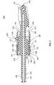
- FIG. 1 is a side elevational view of a drill bit assembly embodying features of the present invention
- FIG. 2 is an exploded perspective view of the drill bit assembly of FIG. 1 embodying features of the present invention
- FIG. 3 is a side cross-sectional view of the drill bit assembly of FIG. 1 embodying features of the present invention.
- FIG. 4 is a perspective view of an alternative adjustable stop having a cam slot embodying features of the present invention.
- a drill bit assembly 100 has a drill bit 102 , a sleeve 104 , and an adjustable stop 106 configured to limit the drill depth of an osteotomy drill within a bore in bone.
- This drill bit assembly 100 provides a practitioner with careful and precise control over the size of a bore and the depth of the bore being drilled. In particular, this assembly provides added safety against a practitioner drilling a bore too deep and breaching into the sinus floor or into the mandibular canal which could cause considerable harm to a patient. Moreover, this assembly provides a sanitary and easy way for the practitioner to disassemble and clean the drill bit assembly 100 between surgical procedures.
- the drill bit 102 has an elongate body 103 including a coronal stem portion 105 for attachment to a drill handpiece and an apical cutting portion 107 .
- the cutting portion 107 of the drill bit includes a tip portion 140 configured to engage a bone in the patient's mouth and form a bore capable of receiving a dental implant or other dental device.
- the cutting portion 107 also has a generally circular flange portion 109 with at least one flat 111 to secure the sleeve 104 on the drill bit as explained below.
- the drill bit 102 is made of metal such as stainless steel.
- the sleeve 104 attaches the adjustable stop 106 to the drill bit assembly 100 .
- the sleeve 104 may be made from a stainless steel or material with similar strength.
- the sleeve 104 has a generally tubular body 108 with a hollow interior 180 , an apical opening 110 , and a coronal opening 112 .
- the sleeve 104 has an outer surface 114 and an inner surface 116 that is configured to fit over and engage an outer surface 182 of the drill bit 102 .
- the sleeve 104 may also include a coronal lip 118 disposed along a coronal section 120 of the sleeve. To rotationally secure the sleeve 104 on the drill bit, the coronal lip 118 has an interior flat 122 that engages the flat 111 of the drill bit 102 .
- the sleeve may have one or more axial grooves 117 to permit the coronal lip 118 to flex, thereby applying radial pressure to the flange 109 , and/or the flat 111 when engaged to provide a tight or friction fit.
- the sleeve 104 may have one or more interiorly extending and circumferentially spaced protrusions 115 that are snap-fit into groove 113 on drill bit 102 .
- the protrusion 115 may be a complete ring, or the coronal lip 118 of the sleeve 104 may snap-fit on the flange portion 104 of the drill bit 102 instead of the groove connection.
- the sleeve 104 may have one or more grooves 117 to permit the coronal lip 118 to flex to snap-fit the sleeve 104 onto the drill bit 102 .
- an axial groove may be provided in the flange 109 and a mating anti-rotation projection provided in the interior of the coronal lip 118 to engage the groove.
- the sleeve 104 and stop 106 are releasably attached to each other by a cam follower 124 .
- the stop 106 has a cam slot that receives a cam follower 124 on the sleeve.
- the cam slot defines a plurality of predetermined axial positions along its length to define different axial positions for the adjustable stop 106 relative to the sleeve 104 and drill bit 102 .
- the sleeve 104 has a cam follower 126 that extends radially outward from the outer surface 114 to engage a corresponding cam slot 128 extending on the adjustable stop 106 .
- the cam follower 126 has a generally cylindrical outer surface 127 .
- the cam follower 126 extends completely through the cam slot 128 . It will be understood, however, that the cam slot may be closed to form an elongate channel with a bottom, and the cam follower 126 merely extends into the slot rather than completely through.
- the adjustable stop 106 has a generally tubular body 184 made of a polymer or other resilient material, an apical opening 130 , a coronal opening 132 , an outer surface 131 , and an inner surface 133 .
- the stop 106 has an apical end section 134 with a rim 138 configured to make contact with bone surrounding the bore, thereby limiting apical motion of the drill bit.
- the cam slot 128 is formed by two opposite elongate edges 143 and 145 that are spaced a distance from one another so as to allow the cam follower 126 to slide within the cam slot 128 .
- the cam slot 128 also defines a plurality of axial positions 166 , 168 , 170 , and 172 .
- each position has at least one protrusion, but here two opposite protrusions 160 and 162 , that extend inward from outer edges 143 and/or 145 and are shaped to secure the cam follower 126 at the axial position.
- the protrusions are shaped to receive the cam follower 126 in a snap-fit that is sufficient to secure the stop 106 both rotationally and axially relative to the sleeve 104 and, in turn, drill bit 102 , while the drill bit undergoes relatively high speed rotation, unless an external force acts on the stop, such as by hand.
- the opposite protrusions 160 and 162 form curved, opposite, concave surfaces 164 that correspond to, and engage, the generally cylindrical cam follower 126 .
- the opposite protrusions 160 and 162 are spaced a distance apart from one another that is narrower than the width of the cam follower 126 .
- the stop 106 is made of a resilient material, the two opposing protrusions 160 and 162 shift away from each other as the cam follower 126 is pressed against the protrusions and onto the curved surfaces 164 . So configured, the protrusions move back to their natural distance apart, thereby securing the cam follower 126 in the predetermined position 166 , 168 , 170 , and 172 .
- a slot may be provided proximate the protrusions 160 and 162 to provide additional flexure to the material for engagement. In one example, the slot may be located on the outer surface 131 , the inner surface 133 , or may extend through both the outer surface 131 and the inner surface 133 .
- the cam slot 128 may include an axial section 144 and a spiral section 147 .
- the axial section 144 extends from a coronal end 149 of the stop, where the slot 128 opens to receive the cam follower 126 of the sleeve.
- the spiral section 147 extends circumferentially from the axial section 144 while extending generally axially about the stop 106 .
- the positions 166 , 168 , 170 , and 172 are defined on the spiral section 147 .
- the positions 166 , 168 , 170 , and 172 are circumferentially spaced at 90 degree intervals around the stop 106 .
- the four positions 166 , 168 , 170 and 172 correspond to four distinct axial positions for the adjustable stop 106 relative to the drill bit 102 .
- a distance ‘d’ is defined from the rim 138 of the adjustable stop 106 to the apical-most tip of the cutting portion 107 of the drill bit 102 .
- the cam follower 126 is disposed at an axial position 166 , 168 , 170 , or 172 .
- the axial positions 166 , 168 , 170 , and 172 have respective associated distances ‘d’ of 13 mm, 11.5 mm, 10 mm, and 8 mm. It will be understood that the number of positions and distances ‘d’ associated with the different positions may vary.
- the stop 106 may also include a strengthening bridge 148 that spans a portion of the cam slot 128 .
- the strengthening bridge 148 may include opposite end sections or columns 150 and 152 that extend radially outward from the outer surface 131 of the stop 106 .
- a beam 154 spans columns 150 and 152 .
- the shape of the strengthening bridge 148 may vary. In this example, the strengthening bridge 148 may span the axial section 144 of the cam slot 128 , and may be spaced from the slot 128 so as to provide clearance for the cam follower 126 to slide past the bridge 148 and into the cam slot 128 .
- the drilling procedure may commence. As the tip 140 of the drill bit 102 engages the bone, a bore will form. The drill bit 102 is advanced in an apical direction during the drilling procedure until the rim 138 of the stop 106 contacts the bone surrounding the bore. When this occurs, the practitioner feels the resistance of the rim 138 contacting the bone, and the advancement of the drill into the bore is stopped.
- the drill bit assembly 100 disclosed in FIGS. 1-3 includes an adjustable stop 206 , instead of stop 106 .
- the adjustable stop 206 may be a generally tubular body 207 that may be made of a polymer or other resilient material.
- the stop 206 has an apical end section 234 configured to engage bone.
- the stop 206 also has a cam slot 242 to receive cam follower 124 .
- the cam slot 242 has an axial section 244 and at least one transverse branch section 247 .
- four branch sections 266 , 268 , 270 , and 272 extend generally perpendicular to the axial section 244 although other directions are contemplated such as diagonal.
- Each branch section 266 , 268 , 270 , and 272 defines an axial position, and includes a corresponding reception or holding area 267 , 269 , 271 , and 273 that opens to a closed section 264 .
- each reception area 267 , 269 , 271 , and 273 includes opposite edges 260 and 262 that secure the cam follower 126 in the closed section 264 .
- the opposite edges 260 and 262 may extend generally parallel to one another and perpendicular to the axial section 244 .
- the opposite edges 260 and 262 are part of two resilient pieces or projections 280 and 282 that are spaced a distance apart from one another but at a distance narrower than the width of the cam follower 126 .
- a groove 281 is provided on projection 282 between adjacent branches to increase resiliency of the edges 260 and 262 . This configuration permits the cam follower 126 to be pressed past the two resilient opposing edges 260 and 262 and snap-fit into the closed section 264 .
- the sleeve portion is not present.
- the drill bit includes a radially extending cam follower to engage the cam slot of the adjustable stop thereby releasably securing the adjustable stop to the drill bit.
- the stop may have the cam follower to engage a cam slot disposed on the sleeve.
- drill bit assembly is mainly described herein for use with a dental surgical procedure, it will be understood that the drill bit assembly may be used with other bone implant surgeries used on other areas of a human body or an animal.
Landscapes
- Health & Medical Sciences (AREA)
- Life Sciences & Earth Sciences (AREA)
- Surgery (AREA)
- Animal Behavior & Ethology (AREA)
- Dentistry (AREA)
- Oral & Maxillofacial Surgery (AREA)
- Orthopedic Medicine & Surgery (AREA)
- Veterinary Medicine (AREA)
- Public Health (AREA)
- General Health & Medical Sciences (AREA)
- Nuclear Medicine, Radiotherapy & Molecular Imaging (AREA)
- Molecular Biology (AREA)
- Medical Informatics (AREA)
- Heart & Thoracic Surgery (AREA)
- Biomedical Technology (AREA)
- Engineering & Computer Science (AREA)
- Otolaryngology (AREA)
- Epidemiology (AREA)
- Surgical Instruments (AREA)
Abstract
Description
Claims (20)
Priority Applications (1)
| Application Number | Priority Date | Filing Date | Title |
|---|---|---|---|
| US12/550,200 US8480682B2 (en) | 2009-08-28 | 2009-08-28 | Device for limiting the drilling depth of a drill |
Applications Claiming Priority (1)
| Application Number | Priority Date | Filing Date | Title |
|---|---|---|---|
| US12/550,200 US8480682B2 (en) | 2009-08-28 | 2009-08-28 | Device for limiting the drilling depth of a drill |
Publications (2)
| Publication Number | Publication Date |
|---|---|
| US20110054483A1 US20110054483A1 (en) | 2011-03-03 |
| US8480682B2 true US8480682B2 (en) | 2013-07-09 |
Family
ID=43625954
Family Applications (1)
| Application Number | Title | Priority Date | Filing Date |
|---|---|---|---|
| US12/550,200 Expired - Fee Related US8480682B2 (en) | 2009-08-28 | 2009-08-28 | Device for limiting the drilling depth of a drill |
Country Status (1)
| Country | Link |
|---|---|
| US (1) | US8480682B2 (en) |
Cited By (11)
| Publication number | Priority date | Publication date | Assignee | Title |
|---|---|---|---|---|
| US9561544B2 (en) | 2011-08-25 | 2017-02-07 | Beth Israel Deaconess Medical Center, Inc. | Methods and devices for safely penetrating materials |
| US10695073B2 (en) | 2017-08-22 | 2020-06-30 | Arthrex, Inc. | Control system for retrograde drill medical device |
| US10695074B2 (en) | 2015-09-03 | 2020-06-30 | Stryker Corporation | Powered surgical drill with integral depth gauge that includes a probe that slides over the drill bit |
| USD893027S1 (en) | 2018-12-21 | 2020-08-11 | Stryker Corporation | Measurement head for surgical tool |
| US10987116B2 (en) | 2017-12-15 | 2021-04-27 | Medos International Sarl | Adjustable drill guides and related methods |
| US11317927B2 (en) | 2017-08-17 | 2022-05-03 | Stryker Corporation | Measurement module for measuring depth of bore holes and related accessories |
| USD954950S1 (en) | 2020-11-18 | 2022-06-14 | Stryker Corporation | Measurement head for a surgical tool |
| US11793558B2 (en) | 2019-08-30 | 2023-10-24 | K2M, Inc. | All in one plate holder and spring loaded awl |
| US11896239B2 (en) | 2017-08-17 | 2024-02-13 | Stryker Corporation | Surgical handpiece system for depth measurement and related accessories |
| USD1030054S1 (en) | 2022-03-18 | 2024-06-04 | Stryker Corporation | Surgical handpiece |
| US12133654B2 (en) | 2019-05-15 | 2024-11-05 | Stryker Corporation | Powered surgical drill having rotating field bit identification |
Families Citing this family (15)
| Publication number | Priority date | Publication date | Assignee | Title |
|---|---|---|---|---|
| US20100299844A1 (en) * | 2010-06-10 | 2010-12-02 | Powers Products Iii, Llc | Drop-in anchor |
| US8603134B2 (en) | 2011-01-14 | 2013-12-10 | Covidien Lp | Latch mechanism for surgical instruments |
| US10603049B2 (en) | 2011-09-02 | 2020-03-31 | Episurf Ip-Management Ab | Implant specific drill bit in surgical kit for cartilage repair |
| EP2564792A1 (en) * | 2011-09-02 | 2013-03-06 | Episurf Medical AB | Modular surgical kit for cartilage repair |
| US11000387B2 (en) | 2011-09-02 | 2021-05-11 | Episurf Ip-Management Ab | Implant for cartilage repair |
| WO2015026955A1 (en) * | 2013-08-21 | 2015-02-26 | Scianamblo Michael J | Precessional drilling and reaming |
| EP3038559B1 (en) * | 2013-08-26 | 2018-10-10 | Elos Medtech Timmersdala AB | Dental drill system |
| WO2015030653A1 (en) * | 2013-08-26 | 2015-03-05 | Elos Medtech Timmersdala Ab | Dental surgery device |
| WO2016004992A1 (en) | 2014-07-09 | 2016-01-14 | Episurf Ip-Management Ab | A surgical joint implant and a bone-mountable rig |
| WO2016004991A1 (en) | 2014-07-09 | 2016-01-14 | Episurf Ip-Management Ab | Customized implant for cartilage repair and corresponding method of design |
| AU2016263600A1 (en) * | 2015-05-21 | 2017-12-07 | Huwais IP Holding LLC | Axial stop gauge and jig guide for surgical drill |
| EP3781048A4 (en) | 2018-04-18 | 2021-06-16 | Michael J. Scianamblo | BONE MATTER COLLECTION DEVICES |
| CN109528265B (en) * | 2018-12-19 | 2024-07-30 | 北京天星博迈迪医疗器械有限公司 | Diameter-variable drill bit and electric drill |
| US20240008903A1 (en) * | 2019-05-22 | 2024-01-11 | Spinal Elements, Inc. | Bone tie and bone tie inserter |
| US12402894B2 (en) * | 2019-08-14 | 2025-09-02 | Versah, LLC | Universal keyless guided surgery system |
Citations (8)
| Publication number | Priority date | Publication date | Assignee | Title |
|---|---|---|---|---|
| US74466A (en) * | 1868-02-11 | Island | ||
| US2231864A (en) * | 1938-08-23 | 1941-02-18 | Cora B Korrer | Attachment for drilling machines |
| US4521145A (en) * | 1982-09-20 | 1985-06-04 | Hans Bieler | Cutting or drilling apparatus |
| US20050147478A1 (en) * | 2003-12-30 | 2005-07-07 | Greenberg Alex M. | Sleeved stop for a drill bit |
| US7261499B2 (en) * | 2004-11-11 | 2007-08-28 | The Boeing Company | Adjustable drill microstop with multiple offset depth settings |
| US20090318927A1 (en) * | 2008-06-23 | 2009-12-24 | Martin Troy D | Adjustable drill guide |
| US20100172706A1 (en) * | 2009-01-05 | 2010-07-08 | Woodworker's Supply Inc. | Countersink assembly |
| US20100215450A1 (en) * | 2009-02-24 | 2010-08-26 | Black & Decker Inc. | Depth Gauge For Drill Bit |
-
2009
- 2009-08-28 US US12/550,200 patent/US8480682B2/en not_active Expired - Fee Related
Patent Citations (8)
| Publication number | Priority date | Publication date | Assignee | Title |
|---|---|---|---|---|
| US74466A (en) * | 1868-02-11 | Island | ||
| US2231864A (en) * | 1938-08-23 | 1941-02-18 | Cora B Korrer | Attachment for drilling machines |
| US4521145A (en) * | 1982-09-20 | 1985-06-04 | Hans Bieler | Cutting or drilling apparatus |
| US20050147478A1 (en) * | 2003-12-30 | 2005-07-07 | Greenberg Alex M. | Sleeved stop for a drill bit |
| US7261499B2 (en) * | 2004-11-11 | 2007-08-28 | The Boeing Company | Adjustable drill microstop with multiple offset depth settings |
| US20090318927A1 (en) * | 2008-06-23 | 2009-12-24 | Martin Troy D | Adjustable drill guide |
| US20100172706A1 (en) * | 2009-01-05 | 2010-07-08 | Woodworker's Supply Inc. | Countersink assembly |
| US20100215450A1 (en) * | 2009-02-24 | 2010-08-26 | Black & Decker Inc. | Depth Gauge For Drill Bit |
Cited By (16)
| Publication number | Priority date | Publication date | Assignee | Title |
|---|---|---|---|---|
| US9561544B2 (en) | 2011-08-25 | 2017-02-07 | Beth Israel Deaconess Medical Center, Inc. | Methods and devices for safely penetrating materials |
| US10695074B2 (en) | 2015-09-03 | 2020-06-30 | Stryker Corporation | Powered surgical drill with integral depth gauge that includes a probe that slides over the drill bit |
| US12605168B2 (en) | 2015-09-03 | 2026-04-21 | Stryker Corporation | Surgical handpiece for determining breakthrough depth of a bore formed in bone |
| US11812977B2 (en) | 2015-09-03 | 2023-11-14 | Stryker Corporation | Method and system for determining breakthrough depth of a bore formed in bone |
| US11317927B2 (en) | 2017-08-17 | 2022-05-03 | Stryker Corporation | Measurement module for measuring depth of bore holes and related accessories |
| US12357322B2 (en) | 2017-08-17 | 2025-07-15 | Stryker Corporation | Surgical handpiece assembly and related accessories |
| US11896239B2 (en) | 2017-08-17 | 2024-02-13 | Stryker Corporation | Surgical handpiece system for depth measurement and related accessories |
| US10695073B2 (en) | 2017-08-22 | 2020-06-30 | Arthrex, Inc. | Control system for retrograde drill medical device |
| US10987116B2 (en) | 2017-12-15 | 2021-04-27 | Medos International Sarl | Adjustable drill guides and related methods |
| USD893027S1 (en) | 2018-12-21 | 2020-08-11 | Stryker Corporation | Measurement head for surgical tool |
| USD955574S1 (en) | 2018-12-21 | 2022-06-21 | Stryker Corporation | Measurement head for surgical tool |
| US12133654B2 (en) | 2019-05-15 | 2024-11-05 | Stryker Corporation | Powered surgical drill having rotating field bit identification |
| US12201335B2 (en) | 2019-08-30 | 2025-01-21 | K2M, Inc. | All in one plate holder and spring loaded awl |
| US11793558B2 (en) | 2019-08-30 | 2023-10-24 | K2M, Inc. | All in one plate holder and spring loaded awl |
| USD954950S1 (en) | 2020-11-18 | 2022-06-14 | Stryker Corporation | Measurement head for a surgical tool |
| USD1030054S1 (en) | 2022-03-18 | 2024-06-04 | Stryker Corporation | Surgical handpiece |
Also Published As
| Publication number | Publication date |
|---|---|
| US20110054483A1 (en) | 2011-03-03 |
Similar Documents
| Publication | Publication Date | Title |
|---|---|---|
| US8480682B2 (en) | Device for limiting the drilling depth of a drill | |
| JP4852183B2 (en) | Implant device and implant device guide system | |
| EP2196162B1 (en) | Drill guide | |
| TWI836129B (en) | Depth stop, and combined osteotome and depth stop assembly | |
| US20180161124A1 (en) | Axial stop gauge and jig guide for surgical drill | |
| US11730573B2 (en) | Fixation pin | |
| BRPI0815672B1 (en) | DRILL GUIDE HAVING A LIMITING AND ASSEMBLY STOP | |
| MX2013014101A (en) | Dental implant jig, set thereof, drilling bar, and set thereof. | |
| EP3934560B1 (en) | A dental drill guiding system | |
| WO2009071885A1 (en) | Stop element for a surgical tool | |
| DK3294156T3 (en) | Surgical hand tools as well as a protective device | |
| AU2011100551A4 (en) | System for guiding a dental arch osteotomy | |
| HK40102060A (en) | Universal keyless guided surgery system | |
| HK40076708B (en) | Universal keyless guided surgery system | |
| HK40076708A (en) | Universal keyless guided surgery system |
Legal Events
| Date | Code | Title | Description |
|---|---|---|---|
| AS | Assignment |
Owner name: ZIMMER DENTAL, INC., CALIFORNIA Free format text: ASSIGNMENT OF ASSIGNORS INTEREST;ASSIGNORS:HOWLETT, CHARLES;NGUYEN, KIM;REEL/FRAME:023271/0533 Effective date: 20090917 |
|
| FEPP | Fee payment procedure |
Free format text: PAYOR NUMBER ASSIGNED (ORIGINAL EVENT CODE: ASPN); ENTITY STATUS OF PATENT OWNER: LARGE ENTITY Free format text: PAYER NUMBER DE-ASSIGNED (ORIGINAL EVENT CODE: RMPN); ENTITY STATUS OF PATENT OWNER: LARGE ENTITY |
|
| STCF | Information on status: patent grant |
Free format text: PATENTED CASE |
|
| FPAY | Fee payment |
Year of fee payment: 4 |
|
| MAFP | Maintenance fee payment |
Free format text: PAYMENT OF MAINTENANCE FEE, 8TH YEAR, LARGE ENTITY (ORIGINAL EVENT CODE: M1552); ENTITY STATUS OF PATENT OWNER: LARGE ENTITY Year of fee payment: 8 |
|
| AS | Assignment |
Owner name: JPMORGAN CHASE BANK, N.A., AS ADMINISTRATIVE AGENT, NEW YORK Free format text: SECURITY INTEREST;ASSIGNORS:BIOMET 3I, LLC;EBI, LLC;ZIMMER BIOMET SPINE, INC.;AND OTHERS;REEL/FRAME:059293/0213 Effective date: 20220228 |
|
| FEPP | Fee payment procedure |
Free format text: MAINTENANCE FEE REMINDER MAILED (ORIGINAL EVENT CODE: REM.); ENTITY STATUS OF PATENT OWNER: LARGE ENTITY |
|
| LAPS | Lapse for failure to pay maintenance fees |
Free format text: PATENT EXPIRED FOR FAILURE TO PAY MAINTENANCE FEES (ORIGINAL EVENT CODE: EXP.); ENTITY STATUS OF PATENT OWNER: LARGE ENTITY |
|
| STCH | Information on status: patent discontinuation |
Free format text: PATENT EXPIRED DUE TO NONPAYMENT OF MAINTENANCE FEES UNDER 37 CFR 1.362 |
|
| FP | Lapsed due to failure to pay maintenance fee |
Effective date: 20250709 |
|
| AS | Assignment |
Owner name: BIOMET 3I, LLC, FLORIDA Free format text: RELEASE OF SECURITY INTEREST;ASSIGNOR:JPMORGAN CHASE BANK, N.A.;REEL/FRAME:073142/0312 Effective date: 20251020 Owner name: ZIMMER DENTAL INC., CALIFORNIA Free format text: RELEASE OF SECURITY INTEREST;ASSIGNOR:JPMORGAN CHASE BANK, N.A.;REEL/FRAME:073142/0312 Effective date: 20251020 Owner name: GOLUB CAPITAL LLC, AS COLLATERAL AGENT, ILLINOIS Free format text: SECURITY INTEREST;ASSIGNORS:BIOMET 3I, LLC;ZIMMER DENTAL INC.;IMPLANT CONCIERGE, LLC;REEL/FRAME:073142/0384 Effective date: 20251020 |