US8480520B2 - Adjustable arrow insert assembly and method of use - Google Patents
Adjustable arrow insert assembly and method of use Download PDFInfo
- Publication number
- US8480520B2 US8480520B2 US13/444,184 US201213444184A US8480520B2 US 8480520 B2 US8480520 B2 US 8480520B2 US 201213444184 A US201213444184 A US 201213444184A US 8480520 B2 US8480520 B2 US 8480520B2
- Authority
- US
- United States
- Prior art keywords
- nut
- arrowhead
- arrowshaft
- bore
- tool
- Prior art date
- Legal status (The legal status is an assumption and is not a legal conclusion. Google has not performed a legal analysis and makes no representation as to the accuracy of the status listed.)
- Active
Links
- 238000000034 method Methods 0.000 title claims description 13
- 238000009434 installation Methods 0.000 claims description 8
- XAGFODPZIPBFFR-UHFFFAOYSA-N aluminium Chemical compound [Al] XAGFODPZIPBFFR-UHFFFAOYSA-N 0.000 description 8
- 229910052782 aluminium Inorganic materials 0.000 description 8
- 150000001875 compounds Chemical class 0.000 description 7
- 239000000853 adhesive Substances 0.000 description 5
- 230000001070 adhesive effect Effects 0.000 description 5
- 239000000463 material Substances 0.000 description 5
- 229920000049 Carbon (fiber) Polymers 0.000 description 4
- 239000004917 carbon fiber Substances 0.000 description 4
- 238000002788 crimping Methods 0.000 description 4
- VNWKTOKETHGBQD-UHFFFAOYSA-N methane Chemical compound C VNWKTOKETHGBQD-UHFFFAOYSA-N 0.000 description 4
- 230000000712 assembly Effects 0.000 description 3
- 238000000429 assembly Methods 0.000 description 3
- 238000011161 development Methods 0.000 description 3
- 238000004140 cleaning Methods 0.000 description 2
- 238000010276 construction Methods 0.000 description 2
- 230000036961 partial effect Effects 0.000 description 2
- 230000006978 adaptation Effects 0.000 description 1
- 238000013461 design Methods 0.000 description 1
- 238000010304 firing Methods 0.000 description 1
- 230000002401 inhibitory effect Effects 0.000 description 1
- 238000003780 insertion Methods 0.000 description 1
- 230000037431 insertion Effects 0.000 description 1
- 230000002452 interceptive effect Effects 0.000 description 1
- 230000000670 limiting effect Effects 0.000 description 1
- 230000000704 physical effect Effects 0.000 description 1
- 239000007787 solid Substances 0.000 description 1
- 229910001220 stainless steel Inorganic materials 0.000 description 1
- 239000010935 stainless steel Substances 0.000 description 1
- 238000012360 testing method Methods 0.000 description 1
Images


Classifications
-
- F—MECHANICAL ENGINEERING; LIGHTING; HEATING; WEAPONS; BLASTING
- F42—AMMUNITION; BLASTING
- F42B—EXPLOSIVE CHARGES, e.g. FOR BLASTING, FIREWORKS, AMMUNITION
- F42B6/00—Projectiles or missiles specially adapted for projection without use of explosive or combustible propellant charge, e.g. for blow guns, bows or crossbows, hand-held spring or air guns
- F42B6/02—Arrows; Crossbow bolts; Harpoons for hand-held spring or air guns
- F42B6/08—Arrow heads; Harpoon heads
-
- Y—GENERAL TAGGING OF NEW TECHNOLOGICAL DEVELOPMENTS; GENERAL TAGGING OF CROSS-SECTIONAL TECHNOLOGIES SPANNING OVER SEVERAL SECTIONS OF THE IPC; TECHNICAL SUBJECTS COVERED BY FORMER USPC CROSS-REFERENCE ART COLLECTIONS [XRACs] AND DIGESTS
- Y10—TECHNICAL SUBJECTS COVERED BY FORMER USPC
- Y10T—TECHNICAL SUBJECTS COVERED BY FORMER US CLASSIFICATION
- Y10T29/00—Metal working
- Y10T29/49—Method of mechanical manufacture
- Y10T29/49826—Assembling or joining
- Y10T29/49947—Assembling or joining by applying separate fastener
- Y10T29/49948—Multipart cooperating fastener [e.g., bolt and nut]
Definitions
- the present invention relates to archery equipment and, more particularly to an arrow insert that allows for the rotational adjustment of an arrowhead relative to the arrowshaft.
- Higher arrow speed has many advantages. For example, it minimizes the time interval during which the game animal might react to the sound of the bow and the impact of the arrow and may thereby enhance shot placement accuracy. Higher speeds also provide for relatively “flatter” arrow flight trajectories within the effective range of the bow which can also enhance accuracy.
- Broadheads are a common type of arrowhead used for hunting and have a plurality of sharp projections or blades that extend radially outwardly from the arrowhead. Broadheads, as well as field points and other types of arrowheads, typically have a threaded shaft that engages a threaded insert that is mounted in the forward end of an arrowshaft. Many people think that the rotational position of the broadhead blades relative to the fletchings on the arrowshaft influences the flight of the arrow. As a result, a person “tuning” an arrow will oftentimes desire to adjust the rotational position of the broadhead blades relative to the fletchings of the arrow.
- the present invention provides an arrow insert assembly that allows for the rotational adjustment of an arrowhead relative to the arrowshaft.
- the invention comprises, in one form thereof, an arrow insert assembly adapted for installation in an arrowshaft having a longitudinally extending bore and further adapted to secure an arrowhead including a threaded stem to the arrowshaft.
- the insert assembly includes a hollow tubular sleeve securable within the bore of the arrowshaft and a nut having a threaded bore and being rotatably positionable within the bore of the arrowshaft aft of at least a portion of the tubular sleeve.
- the arrowhead is securable to the arrowshaft in a desired rotational position by extending the threaded stem through the tubular sleeve and securely engaging the threaded stem with the threaded bore of the nut.
- the invention comprises, in another form thereof, an arrow assembly that includes an arrowshaft having a longitudinally extending bore and an arrowhead including a plurality of outwardly extending blades and a threaded stem, the stem being fixed and immovable relative to the blades.
- the arrow assembly also includes a hollow tubular sleeve secured within the bore of the arrowshaft and a nut having a threaded bore, the nut being positioned aft of at least a portion of the tubular sleeve wherein the arrowhead is secured to the arrowshaft by extending the threaded stem through the tubular sleeve to securely engage the threaded bore of the nut.
- the invention comprises, in yet another form thereof, a method of securing an arrowhead having a threaded stem to an arrowshaft having a longitudinally extending bore.
- the method includes installing a hollow tubular sleeve within the bore of the arrowshaft; positioning a nut having a threaded bore within the bore and aft of at least a portion of the sleeve, the nut being rotatable relative to the tubular sleeve; and securing the arrowhead in a desired rotational position by inserting the threaded stem of the arrowhead through the sleeve and threadingly and securely engaging the stem with the threaded bore of the nut.
- the insert assembly is adapted for use with an arrowshaft having an opening at the aft end of the shaft such as a carbon fiber shaft.
- the nut is engaged with a tool inserted through the aft end of the arrowshaft to engage and rotatably drive the nut and threadingly engage the nut with the threaded stem of the arrowhead.
- the tool has a collapsible shaft with at least one pivotal link.
- the insert assembly is adapted for use with an arrowshaft having a closed aft end such as an aluminum shaft.
- the sleeve includes axially extending crimp arms extending rearwardly from the sleeve. The crimp arms axially capture the nut but allow rotational movement of the nut relative to the sleeve.
- the threaded stem of the arrowhead is inserted through the sleeve and engaged with the nut. To secure the arrowhead, the arrowhead is rotated relative to the arrowshaft to threadingly engage the stem with the nut.
- the arrowhead is loosened from the nut, the nut is allowed to rotate relative to the sleeve and then the arrowhead is re-secured. This process is repeated until the arrowhead is secured in the desired rotational position.
- the insert assembly comes with a plurality of nuts which define a plurality of different weights whereby a selected one of the nuts can be utilized to secure the arrowhead and thereby selectively control the distribution of weight along the arrowshaft.
- FIG. 1 is an exploded perspective view of an arrow utilizing one embodiment of an adjustable insert and a tool used with the adjustable insert.
- FIG. 2 is a cross sectional view of the arrow assembly with the adjustable insert of FIG. 1 in an installed condition.
- FIG. 3 is an exploded perspective view of a broadhead, the adjustable insert of FIG. 1 and an installation tool.
- FIG. 4 is a side view of an alternative embodiment of a sleeve for an adjustable insert.
- FIG. 5 is a view of a set of differently weighted nuts for an adjustable insert.
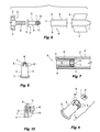
- FIG. 6 is a partial exploded view of an alternative embodiment of the adjustable insert usable with arrowshafts having a shaft with a closed aft end.
- FIG. 7 is a cross sectional view of the adjustable insert of FIG. 6 in an installed condition.
- FIG. 8 is a perspective view of the adjustable insert of FIG. 6 .
- FIG. 9 is an exploded perspective view of the adjustable insert of FIG. 6 prior to assembly.
- FIG. 10 is a partial cross sectional view of the adjustable insert of FIG. 6 .
- FIG. 11 is a side view of an alternative installation tool.
- FIG. 12 is a side view of a grip for use with an installation tool.
- FIG. 13 is an end view of an installation tool grip.
- FIG. 14 is side view of an alternative installation tool with pivotal links.
- FIG. 15 is a perspective view of a pivotal link.
- FIG. 16 is a side view of an alternative insert and nut which are adapted for use with a crossbow bolt.
- FIG. 1 An arrow assembly 20 having an adjustable insert assembly 22 is illustrated in FIG. 1 .
- arrow 20 includes a broadhead 24 having a plurality of radially outwardly extending blades 26 and a threaded stem 28 .
- Broadhead 24 is a conventional broadhead wherein blades 26 do not rotate relative to stem 28 .
- Blades 26 may be removable, for sharpening or replacement, or permanently affixed to broadhead 24 .
- Arrow 20 also includes a shaft 30 having a fore end 32 and an aft end 34 .
- Insert assembly 22 and broadhead 24 are secured to shaft 30 at fore end 32 .
- a plurality of fletchings 36 typically three fletchings, extend radially outwardly from the shaft 30 proximate aft end 34 .
- a nock 38 is installed in the aft end 34 of shaft 30 for engagement with the string of the bow used to fire arrow 20 .
- shaft 30 is a conventional carbon fiber shaft in the form of a hollow cylindrical tube which is open at both the fore and aft ends 32 , 34 .
- broadhead 24 is a conventional broadhead.
- fletchings 36 and nock 38 are conventional and employed with shaft 30 in a manner well known to those having ordinary skill in the art.
- specific arrow assemblies 20 are shown and described herein, the present invention may be used with a variety of different arrow assemblies adapted for use with a variety of different bows.
- the present invention may be used with arrows adapted for use with compound bows and more traditional bows such as recurve bows and long bows.
- the present invention may also be used with arrows specifically adapted for use with crossbows which are commonly referred to as “bolts”.
- adjustable insert assembly 22 includes both a sleeve 40 and a nut 42 .
- Sleeve 40 is secured in the fore end 32 of shaft 30 .
- Sleeve 40 includes a radially outwardly projecting flange or collar 44 that has an outermost surface 46 that defines a diameter substantially similar to the diameter defined by the outermost surface 31 of shaft 30 .
- Sleeve 40 also has a tubular section 48 which has an outer surface 50 .
- Outer surface 50 has a diameter sized to tightly fit within bore 29 of shaft 30 .
- An axial bore 52 extends through sleeve 40 and has a diameter sufficiently large to allow the passage of threaded stem 28 therethrough without inhibiting the axial passage or rotational movement of threaded stem 28 . In the illustrated embodiment, bore 52 does not engage threaded stem 28 .
- Sleeve 40 is secured to shaft 30 by inserting tubular section in bore 29 as can be seen in FIG. 2 .
- Sleeve 40 is securely affixed to shaft 30 either by the press-fit engagement between sleeve 40 and bore 29 , by applying a layer of adhesive between exterior surface 50 of tubular section 48 and bore 29 , or other suitable means known to those having ordinary skill in the art.
- Sleeve 40 is installed in shaft 30 in a manner similar to the installation in an arrowshaft of a conventional insert having a threaded interior.
- Conventional arrow inserts have a shape and construction generally similar to sleeve 40 but include a threaded bore for directly engaging and securing the threaded stem 28 of an arrowhead.
- FIG. 4 illustrates an alternative sleeve 40 a which includes circumferentially extending grooves 54 in exterior surface 50 and is particularly well adapted for securing sleeve 40 a to a shaft 30 with adhesive.
- Grooves 54 are useful for retaining adhesive during the securement of sleeve 40 a to shaft 30 .
- the use of such adhesive grooves with conventional inserts is known in the art.
- tubular section 48 When installing sleeves 40 , 40 a in an arrowshaft 30 , tubular section 48 is inserted in bore 29 of shaft 30 until the aft-facing surface 56 of collar 44 is engaged with the axial face 33 of fore end 32 . When mounting an arrowhead, the arrowhead engages the collar 44 while nut 42 engages the opposite end of the sleeve defined by aft-facing surface 58 of tubular section 48 as discussed below.
- Nut 42 is positioned within bore 29 aft of sleeve 40 .
- Nut 42 is dimensioned to allow nut 42 to be rotated within bore 29 .
- nut 42 has a cylindrical exterior surface 60 which is sufficiently smaller than the interior diameter of bore 29 to allow for relatively easy rotation of nut 42 but sufficiently large so that positioning nut 42 within bore 29 properly centers and positions nut 42 within bore 29 .
- Nuts 42 may also be used which have alternative shapes, for example a nut having an outer perimeter defining a hexagon or octagon could be used provided that such nuts were rotatable within bore 29 .
- Nut 42 includes a threaded bore 62 which is threadingly engageable with threaded stem 28 .
- Nut 42 also has an axial face 64 on the fore end of nut 42 that is generally planar.
- the axial face 66 on the aft end of nut 42 defines a plurality of slots 68 that are engageable with a driver.
- slots 68 are engageable with a driver having a “Phillips” head configuration, however, other configurations which allow for the rotational driving of nut 42 can also be employed with nut 42 .
- nut 42 When installing an arrowhead on shaft 30 , nut 42 is positioned within bore 29 aft of sleeve 40 which is securely affixed to shaft 30 .
- the threaded stem 28 of the arrowhead is inserted through sleeve 40 and engaged with threaded bore 62 of nut 42 .
- the arrowhead is positioned in a desired rotational position, e.g., broadhead blades 26 are rotationally aligned with fletchings 36 , and the nut 42 is then rotated within bore 29 until the axial face 64 of the fore end of nut 42 firmly and securely engages the aft-facing surface 58 of sleeve 40 thereby securing the arrowhead to shaft 30 .
- stem 28 having threads extending the full length of stem 28
- the present invention can also be employed with arrowheads having a stem wherein a portion of the stem has a non-threaded exterior, e.g., a smooth cylindrical shank, with only the most distal portion of the stem being threaded.
- Tool 70 is illustrated in FIG. 1 and can be used to rotate nut 42 when securing or removing the arrowhead from shaft 30 .
- Tool 70 includes an elongate shaft 72 having a grip 78 at one end and a driver 76 at the other end.
- shaft 72 has a three part shaft with the individual lengths of shaft 72 being threadingly secured together.
- Alternative embodiments of tool 70 may also be used.
- the shaft of tool 70 can also take the form of a single piece rod that does not break down into smaller lengths.
- Tool 70 can be conveniently constructed by mounting a driving bit 76 on the end of a cleaning rod designed for use with .22 caliber rifles. Cleaning rods designed for .22 caliber rifles have a diameter that allows for their insertion into the bore of a conventional carbon fiber arrowshaft.
- shaft 72 is assembled into a single elongate structure and the driver 76 is inserted into bore 29 at the aft end 34 of shaft 30 .
- the driver 76 is then engaged with slots 68 on nut 42 .
- the user then manually rotates grip 78 to turn nut 42 on stem 28 as the arrowhead is held in the desired rotational orientation.
- nock 38 is positioned in bore 29 at the aft end 34 of shaft 30 thereby fully assembling the arrow.
- Nocks 38 are often press-fit in the aft end of an arrowshaft instead of permanently adhering the nock therein. Later removal of the nock from the aft end allows tool 70 to be later re-inserted in bore 29 if it is later desired to remove the arrowhead or adjust the rotational position of the arrowhead. As mentioned above, the capability to selectively adjust the rotational position of the arrowhead is useful when “tuning” an arrow.
- FIG. 5 illustrates how the adjustable insert assembly 22 can optionally be provided with multiple nuts 42 a , 42 b , 42 c to further enhance the tuning capabilities of insert assembly 22 .
- Nuts 42 a , 42 b , 42 c have threaded interior bores and the same general construction and functionality as nut 42 but are provided as a set of three with sleeve 40 .
- Each of the nuts 42 a , 42 b , 42 c has a slightly different weight to thereby allow the user to select the nut 42 a , 42 b , 42 c that provides the optimal weight distribution for arrow assembly 20 .
- tuning an arrow it is often desirable to adjust the weight-forward or front-of-center weight of the arrow.
- differently weighted nuts 42 a , 42 b , 42 c allows for the relatively easy adjustment of the front-of-center weight of the arrow assembly.
- the illustrated example shows the use of three differently weighted nuts, various other numbers of differently weighted nuts could be provided. For example, a set of five nuts having different weights could be used with the present invention.
- nuts 42 a , 42 b , 42 c are made of the same material but have different lengths to thereby provide for the difference in weight between the individual nuts 42 a , 42 b , 42 c .
- Alternative methods may also be employed to provide a plurality of nuts having different weights.
- different materials having different densities could be used to provide differently weighted nuts having common dimensions, or, nuts having a common length and made of a common material could have one or more laterally extending bores formed therein to provide differently weighted nuts.
- Such lateral bores would extend perpendicular to the threaded axial bore of the nut.
- nuts 42 a , 42 b , 42 c and sleeve 40 could all be provided in different materials having different densities.
- these components could all be provided in both aluminum and stainless steel.
- FIG. 6 illustrates an arrow assembly 80 having an aluminum arrowshaft 82 with a closed aft end 84 and an insert assembly 90 that can be employed therewith.
- Aluminum shaft 82 includes fletchings 36 similar to shaft 30 and a fore end 86 having an opening 87 to substantially cylindrically shaped, longitudinally extending, blind bore 88 .
- a conventional broadhead 24 and other arrowheads having a conventional threaded stem 28 can be used with insert assembly 90 .
- Insert assembly 90 includes a sleeve 92 and a nut 94 .
- Sleeve 92 has a collar 96 and a tubular section 98 that are similar to the collar 44 and tubular section 48 of sleeve 40 and, thus, a discussion of these features will not be repeated.
- Sleeve 92 differs from sleeve 40 by including a plurality of crimping arms 100 that extend rearwardly from the back of tubular section 98 .
- tubular section 98 defines an axial surface 102 facing the aft end 84 of shaft 82 .
- Crimping arms 100 are located along the outer radial portion of surface 102 and define a radially inward shoulder which is engageable with axial surface 104 on the fore end of nut 94 .
- Crimping arms 100 axially capture nut 94 while still allowing limited rotational movement between nut 94 and sleeve 92 .
- FIG. 9 illustrates sleeve 92 and nut 94 before final assembly of insert 90 and the inward crimping of arms 100 .
- Nut 94 is positioned adjacent surface 102 while arms 100 are still straight as depicted in FIG. 9 .
- the crimp arms 100 are then bent radially inwardly axially capturing nut 94 adjacent surface 102 .
- the crimp arms 100 are not, however, so firmly engaged with nut 94 to prevent all rotation of nut 94 .
- insert assembly 90 is secured within shaft 82 .
- tubular section 98 is secured to shaft 82 either by a sufficiently tight press-fit engagement or by means of an adhesive.
- an arrowhead 24 having a threaded stem 28 can be attached to assembly 90 .
- threaded stem 28 is inserted through the central bore of sleeve 92 and engaged with threaded bore 106 of nut 94 .
- the arrowhead is then rotated relative to shaft 82 to threadingly engage stem 28 with nut 94 and firmly secure stem 28 with nut 94 as surface 104 on nut 94 is brought into engagement with surface 102 on sleeve 92 . If the final rotational position of the arrowhead is not the desired rotational position, the arrowhead is rotated in the opposite direction thereby loosening the arrowhead.
- FIG. 16 Another alternative embodiment is shown in FIG. 16 .
- the adjustable insert assembly depicted in FIG. 16 includes a sleeve 134 and a nut 42 which are adapted for use in a crossbow bolt.
- Crossbow bolts typically have shafts which are shorter than arrows used with other bows.
- Crossbow bolts also typically have a larger diameter shaft with a larger diameter inner bore in comparison to arrows used with other bows.
- the larger diameter inner bore of the crossbow bolt requires the use of a larger diameter sleeve 134 .
- many crossbow bolts have a length between about 20 to about 22 inches while arrows used with other bows typically have lengths which are between about 27 inches to about 32 inches.
- the inner diameter of many crossbow bolts is about 0.300 inches while the inner diameter or arrows for other bows is often about 0.25 inches. While such dimensions are commonly used with crossbows and other bows, various other dimensions can also be employed with the adjustable inserts disclosed herein.
- sleeve 134 has a tubular section 48 with a collar 44 that engages the end of the shaft and an axially extending bore.
- the bore includes a smaller diameter section 53 proximate collar 44 and a larger diameter section 136 which receives nut 42 .
- the threaded stem of an arrowhead is inserted through smaller diameter section 53 and is engaged with the threaded bore 62 of nut 42 .
- Nut 42 fits within bore section 136 and is tightened down into engagement with aft-facing surface 138 to secure the arrowhead to crossbow shaft.
- Slots 68 on nut 42 form an interface for engaging a driver inserted through the aft end of the crossbow shaft.
- a sleeve 134 having a bore with a larger diameter section 136 that receives nut 42 allows for the use of a longer and thereby heavier sleeve 134 with conventional arrowheads.
- Many arrowheads have a stem with a combined length of about 0.625 inches for a threaded stem including both a non-threaded shank and threaded length of the threaded stem.
- the length of small diameter section 53 must be sufficiently shorter than 0.625 inches to allow for nut 42 to firmly engage the threaded stem.
- sleeve 134 can extend aft of engagement surface 138 without interfering with nut 42 and thereby increase the weight of sleeve 134 .
- sleeve 134 is approximately 80 grams while nut 42 is approximately 50 grams, however, various other weights for sleeve 134 and nut 42 may also be employed with the present invention. Larger diameter nuts 42 could also be employed in crossbow shafts to provide increased weight, however, the embodiment depicted in FIG. 16 allows nuts 42 suitable for conventional arrowshafts to be used in crossbow bolts while still providing enhanced weight for the insert assembly.
- FIGS. 11-15 illustrate alternative tools that can be used to install and remove adjustable insert assembly 22 .
- FIG. 11 illustrates an elongate rod 108 having a driver 76 at one end and a threaded section 110 at the opposite end.
- elongate rod 108 is generally similar to tool 70 but has a continuous shaft rather than a separable shaft and has a threaded section 110 instead of grip 78 .
- Threaded section 110 is engageable with nut 42 whereby if it is desired to remove a nut 42 from an arrowshaft 30 , threaded section 110 can be threaded into engagement with threaded bore 62 of the nut 42 and then the elongate rod 108 and attached nut 42 can be pulled from the arrowshaft 30 .
- the use of a tool having a threaded section 110 can be particularly useful when using a plurality of nuts having different weights such as those depicted in FIG. 5 .
- the first nut 42 a could be initially installed and the assembled arrow could be shot to determine how well it flew. Nut 42 a could then be removed and one of the other nuts 42 b , 42 c could then installed and the arrow tested again. After installing and testing each of the nuts 42 a , 42 b , 42 c , the one which performed best with the arrow could be re-installed. Oftentimes, archers/hunters will assemble multiple arrows having the same general configuration.
- the archer could then assemble numerous arrows having the same configuration as the initial arrow, e.g., same shaft material and length, same fletchings, same arrowhead and same weight nut 42 a , 42 b or 42 c.
- grip 112 includes a through bore 114 through which rod 108 can be inserted.
- Grip 112 also includes a threaded cross bore 116 which intersects through bore 114 .
- a set screw 118 is positioned in threaded bore. When grip 112 is positioned at the desired location on elongate rod 108 , set screw 118 is rotated into tight engagement with rod 108 to thereby secure grip 112 in place. Grip 112 can then be used to rotate rod 108 when installing and removing nuts 42 .
- set screw 118 When it is desired to reposition grip 112 , set screw 118 is loosened thereby allowing grip 112 to be repositioned on rod 108 or removed therefrom.
- Set screw has one end (not shown) which is adapted for engagement with a driver such as an Allen wrench or screwdriver as will be readily understood by a person having ordinary skill in the art.
- arrows are typically no more than 32 inches in length and a rod 108 having a length of approximately 32 and 3 ⁇ 8 inches will work with nearly all arrows. Or course a suitably longer rod 108 could be provided for use with custom arrows having a longer length. For most hunters and non-hunting archers, transporting rod 108 and grip 112 will not pose a difficulty. Rod 108 will generally not be significantly longer than the associated arrows. As a result, rod 108 will oftentimes be easily transported in a quiver or bow case that the archer/hunter uses to transport his arrows.
- rod 108 depicted in FIG. 11 is a solid continuous rod which cannot be broken down into shorter lengths, it could alternatively be formed out of several shorter shaft lengths in a manner similar to tool 70 . Collapsible rods may also be employed. Rods which can be broken down or collapsed provide even greater options for storing and transporting the rod.
- FIGS. 14 and 15 An example of a pivotally collapsible rod 120 is depicted in FIGS. 14 and 15 .
- the illustrated rod 120 has three short shaft lengths 122 which are connected by pivotal links 124 .
- collapsible rod 120 has a driver 76 at one end and a threaded section 110 at the opposite end.
- FIG. 14 illustrates rod 120 in an extended configuration which allows rod 120 to be inserted into the bore 29 of an arrowshaft 30 .
- a grip 112 can be secured on rod 120 and rod 120 can be used in the same manner as elongate rod 108 to install and remove insert assemblies 22 .
- arrowshaft 30 will restrain the pivotal movement of link 124 .
- rod 120 When not in use, rod 120 can be collapsed to approximately one third of its fully extended length by means of pivotal links 124 .
- pivotal links 124 Although the illustrated rod 120 has two links 124 and can be collapsed to one third its fully extended length, more or fewer links 124 can also be employed.
- a single link 124 could be used to collapse an alternative rod configuration to approximately one half its fully extended length or three lengths could be employed to collapse a rod to approximately one fourth its fully extended length.
- Pivotal links 124 are best understood with reference to FIG. 15 .
- Pivotal links 124 include a link member 126 which takes the form of a small flat bar in the illustrated embodiment. Slots 128 are formed in adjacent ends of shaft lengths 122 creating a pair of arms 130 on the end of each shaft length 122 . Holes are drilled or otherwise formed in arms 130 and near each end of link member 126 to receive pivot pins 132 . Slot 128 is advantageously formed sufficiently deep such that the bottom of slot 128 does not limit the rotation of link member 126 . The use of a such a deep slot will allow link members 126 to rotate sufficiently to allow shaft lengths 122 to be positioned immediately adjacent along their full length when rod 120 is positioned in a collapsed configuration.
Landscapes
- Engineering & Computer Science (AREA)
- General Engineering & Computer Science (AREA)
- Mutual Connection Of Rods And Tubes (AREA)
Abstract
Description
Claims (20)
Priority Applications (1)
| Application Number | Priority Date | Filing Date | Title |
|---|---|---|---|
| US13/444,184 US8480520B2 (en) | 2011-04-20 | 2012-04-11 | Adjustable arrow insert assembly and method of use |
Applications Claiming Priority (2)
| Application Number | Priority Date | Filing Date | Title |
|---|---|---|---|
| US201161477389P | 2011-04-20 | 2011-04-20 | |
| US13/444,184 US8480520B2 (en) | 2011-04-20 | 2012-04-11 | Adjustable arrow insert assembly and method of use |
Publications (2)
| Publication Number | Publication Date |
|---|---|
| US20120270688A1 US20120270688A1 (en) | 2012-10-25 |
| US8480520B2 true US8480520B2 (en) | 2013-07-09 |
Family
ID=47021760
Family Applications (1)
| Application Number | Title | Priority Date | Filing Date |
|---|---|---|---|
| US13/444,184 Active US8480520B2 (en) | 2011-04-20 | 2012-04-11 | Adjustable arrow insert assembly and method of use |
Country Status (1)
| Country | Link |
|---|---|
| US (1) | US8480520B2 (en) |
Cited By (12)
| Publication number | Priority date | Publication date | Assignee | Title |
|---|---|---|---|---|
| USD709978S1 (en) * | 2013-01-16 | 2014-07-29 | Rac Em Bac, L.L.C. | Arrowhead |
| US9410773B2 (en) * | 2014-07-14 | 2016-08-09 | Aldila Golf Corp. | Adjustable archery arrow insert |
| US20170138707A1 (en) * | 2015-11-16 | 2017-05-18 | Slick Trick Llc | Arrowhead adapter and assembly operable with multiple types of arrow shafts |
| US20170299353A1 (en) * | 2014-07-14 | 2017-10-19 | Aldila Golf Corp. | Adjustable Archery Arrow Insert |
| US9915510B1 (en) * | 2017-04-22 | 2018-03-13 | Dorge O. Huang | Variable weighted arrow tip |
| US20180347955A1 (en) * | 2016-02-01 | 2018-12-06 | Jerome Edward Gizowski | Spin Point for Archery Arrows |
| US10859354B1 (en) * | 2020-02-21 | 2020-12-08 | Dorge O. Huang | Arrow insert with threaded stem for retaining an arrow tip |
| US11098994B1 (en) * | 2020-02-21 | 2021-08-24 | Dorge O. Huang | Arrow insert with threaded stem for retaining an arrow tip |
| US11105594B2 (en) * | 2019-07-16 | 2021-08-31 | Matthew G. Decker | Pivotable arrowhead assembly |
| US11740060B2 (en) | 2022-01-06 | 2023-08-29 | Richard M. Forrest | Arrow system |
| US20230358517A1 (en) * | 2022-01-06 | 2023-11-09 | Richard M. Forrest | Arrow system |
| US12188753B1 (en) * | 2021-12-30 | 2025-01-07 | Matthew Futtere | Mechanical shaft insert/outsert apparatus and method |
Families Citing this family (3)
| Publication number | Priority date | Publication date | Assignee | Title |
|---|---|---|---|---|
| US8382616B2 (en) * | 2007-01-24 | 2013-02-26 | John Marshall | Fletching system and method therefor |
| US9097500B1 (en) * | 2014-02-03 | 2015-08-04 | Thomas Andrew Addleman | Modular adjustable weight arrow tip |
| US20250283702A1 (en) * | 2024-03-05 | 2025-09-11 | Grace Engineering Corp. | Archery arrow and related method of manufacture |
Citations (19)
| Publication number | Priority date | Publication date | Assignee | Title |
|---|---|---|---|---|
| US4006901A (en) | 1975-10-06 | 1977-02-08 | New Archery Products Corporation | Arrowhead |
| US4203601A (en) | 1975-10-06 | 1980-05-20 | New Archery Products Corp. | Arrowhead |
| US4210330A (en) | 1978-02-13 | 1980-07-01 | Dynamic Sports concepts, Inc. | Modular broadhead arrowhead |
| US4534568A (en) | 1981-11-09 | 1985-08-13 | Tone Richard D | Archery arrow with freely rotational broad blade arrowhead to avoid windplaning |
| US4621817A (en) | 1985-12-11 | 1986-11-11 | John Musacchia | Broadhead arrow with axial alignment device |
| US4671517A (en) | 1984-03-16 | 1987-06-09 | Winters Danny J | Apparatus for rotatably mounting arrowheads |
| US4781386A (en) | 1987-07-31 | 1988-11-01 | Armitage George E | Fletching alignment nut |
| US4943067A (en) | 1985-02-11 | 1990-07-24 | Saunders Thomas A | Arrow insert |
| US5803843A (en) | 1994-06-29 | 1998-09-08 | Anderson; Vaughn R. | Lockable arrow nock |
| US5823902A (en) | 1997-10-08 | 1998-10-20 | Guest; Elmer F. | Nock assembly for arrows |
| US5902199A (en) * | 1998-01-13 | 1999-05-11 | Adams, Jr.; Charles C. | Archery arrow tuning method and apparatus |
| US6887172B2 (en) | 2001-04-12 | 2005-05-03 | Gregory B. Arasmith | Arrow broadhead |
| US7207908B1 (en) | 2006-02-16 | 2007-04-24 | Frederick Scott Gizowski | Insert for allowing the free rotation of a cutting tip on an arrow shaft |
| US7232390B2 (en) | 2003-01-16 | 2007-06-19 | New Archery Products Corp. | Lockable rotatable arrowhead |
| US7318783B2 (en) | 2005-11-29 | 2008-01-15 | Polando Scott A | Adjustable weight broadhead adapter bolt and arrow |
| US7338397B2 (en) | 2003-01-16 | 2008-03-04 | New Archery Products Corp. | Rotatable arrowhead |
| US20090124439A1 (en) | 2007-11-14 | 2009-05-14 | Kevin Michael Sullivan | Tunable broadhead |
| US7651421B2 (en) | 2005-10-11 | 2010-01-26 | Jas. D. Easton, Inc. | Arrow insert apparatus |
| US8016703B1 (en) * | 2009-08-25 | 2011-09-13 | Precision Shooting Equipment, Inc. | Arrow shaft insert |
-
2012
- 2012-04-11 US US13/444,184 patent/US8480520B2/en active Active
Patent Citations (19)
| Publication number | Priority date | Publication date | Assignee | Title |
|---|---|---|---|---|
| US4006901A (en) | 1975-10-06 | 1977-02-08 | New Archery Products Corporation | Arrowhead |
| US4203601A (en) | 1975-10-06 | 1980-05-20 | New Archery Products Corp. | Arrowhead |
| US4210330A (en) | 1978-02-13 | 1980-07-01 | Dynamic Sports concepts, Inc. | Modular broadhead arrowhead |
| US4534568A (en) | 1981-11-09 | 1985-08-13 | Tone Richard D | Archery arrow with freely rotational broad blade arrowhead to avoid windplaning |
| US4671517A (en) | 1984-03-16 | 1987-06-09 | Winters Danny J | Apparatus for rotatably mounting arrowheads |
| US4943067A (en) | 1985-02-11 | 1990-07-24 | Saunders Thomas A | Arrow insert |
| US4621817A (en) | 1985-12-11 | 1986-11-11 | John Musacchia | Broadhead arrow with axial alignment device |
| US4781386A (en) | 1987-07-31 | 1988-11-01 | Armitage George E | Fletching alignment nut |
| US5803843A (en) | 1994-06-29 | 1998-09-08 | Anderson; Vaughn R. | Lockable arrow nock |
| US5823902A (en) | 1997-10-08 | 1998-10-20 | Guest; Elmer F. | Nock assembly for arrows |
| US5902199A (en) * | 1998-01-13 | 1999-05-11 | Adams, Jr.; Charles C. | Archery arrow tuning method and apparatus |
| US6887172B2 (en) | 2001-04-12 | 2005-05-03 | Gregory B. Arasmith | Arrow broadhead |
| US7232390B2 (en) | 2003-01-16 | 2007-06-19 | New Archery Products Corp. | Lockable rotatable arrowhead |
| US7338397B2 (en) | 2003-01-16 | 2008-03-04 | New Archery Products Corp. | Rotatable arrowhead |
| US7651421B2 (en) | 2005-10-11 | 2010-01-26 | Jas. D. Easton, Inc. | Arrow insert apparatus |
| US7318783B2 (en) | 2005-11-29 | 2008-01-15 | Polando Scott A | Adjustable weight broadhead adapter bolt and arrow |
| US7207908B1 (en) | 2006-02-16 | 2007-04-24 | Frederick Scott Gizowski | Insert for allowing the free rotation of a cutting tip on an arrow shaft |
| US20090124439A1 (en) | 2007-11-14 | 2009-05-14 | Kevin Michael Sullivan | Tunable broadhead |
| US8016703B1 (en) * | 2009-08-25 | 2011-09-13 | Precision Shooting Equipment, Inc. | Arrow shaft insert |
Non-Patent Citations (1)
| Title |
|---|
| Sullivan Industries Inc., Innerloc Broadheads, Tuning the new BAT broadheads, www.innerloc.com/pages/bat-tech3.htm, copyright 1997-2011. |
Cited By (16)
| Publication number | Priority date | Publication date | Assignee | Title |
|---|---|---|---|---|
| USD709978S1 (en) * | 2013-01-16 | 2014-07-29 | Rac Em Bac, L.L.C. | Arrowhead |
| US9410773B2 (en) * | 2014-07-14 | 2016-08-09 | Aldila Golf Corp. | Adjustable archery arrow insert |
| US9772169B2 (en) | 2014-07-14 | 2017-09-26 | Aldila Golf Corporation | Adjustable archery arrow insert |
| US20170299353A1 (en) * | 2014-07-14 | 2017-10-19 | Aldila Golf Corp. | Adjustable Archery Arrow Insert |
| US20170138707A1 (en) * | 2015-11-16 | 2017-05-18 | Slick Trick Llc | Arrowhead adapter and assembly operable with multiple types of arrow shafts |
| US9879956B2 (en) * | 2015-11-16 | 2018-01-30 | Slick Trick Llc | Arrowhead adapter and assembly operable with multiple types of arrow shafts |
| US20180347955A1 (en) * | 2016-02-01 | 2018-12-06 | Jerome Edward Gizowski | Spin Point for Archery Arrows |
| US9915510B1 (en) * | 2017-04-22 | 2018-03-13 | Dorge O. Huang | Variable weighted arrow tip |
| US11105594B2 (en) * | 2019-07-16 | 2021-08-31 | Matthew G. Decker | Pivotable arrowhead assembly |
| US10859354B1 (en) * | 2020-02-21 | 2020-12-08 | Dorge O. Huang | Arrow insert with threaded stem for retaining an arrow tip |
| US11098994B1 (en) * | 2020-02-21 | 2021-08-24 | Dorge O. Huang | Arrow insert with threaded stem for retaining an arrow tip |
| US12188753B1 (en) * | 2021-12-30 | 2025-01-07 | Matthew Futtere | Mechanical shaft insert/outsert apparatus and method |
| US11740060B2 (en) | 2022-01-06 | 2023-08-29 | Richard M. Forrest | Arrow system |
| US20230358517A1 (en) * | 2022-01-06 | 2023-11-09 | Richard M. Forrest | Arrow system |
| US11859960B2 (en) | 2022-01-06 | 2024-01-02 | Richard M. Forrest | Arrow system |
| US12305968B2 (en) * | 2022-01-06 | 2025-05-20 | Richard M. Forrest | Arrow system |
Also Published As
| Publication number | Publication date |
|---|---|
| US20120270688A1 (en) | 2012-10-25 |
Similar Documents
| Publication | Publication Date | Title |
|---|---|---|
| US8480520B2 (en) | Adjustable arrow insert assembly and method of use | |
| US8016703B1 (en) | Arrow shaft insert | |
| US5987724A (en) | Crossbow bolt cap and fletching nock device and method | |
| US4671517A (en) | Apparatus for rotatably mounting arrowheads | |
| US7331886B2 (en) | Sliding arrow stabilizer | |
| CA2543031C (en) | Arrow system | |
| US8449413B1 (en) | Non-lethal arrow | |
| US8267815B2 (en) | Nock adapter for bowfishing arrow | |
| US20250027756A1 (en) | Adjustable outsert system | |
| US5934001A (en) | Archery accessory and method | |
| US2905166A (en) | Bow string nock | |
| WO2013106786A2 (en) | Small diameter crossbow bolt | |
| US11022413B1 (en) | Arrow insert with reinforcing collar | |
| US10809044B2 (en) | Mechanical blade retention system for archery broadhead | |
| US9658037B2 (en) | Arrow tip mounting apparatus and method | |
| US7207908B1 (en) | Insert for allowing the free rotation of a cutting tip on an arrow shaft | |
| US20100167849A1 (en) | Arrow | |
| US8167747B2 (en) | Arrowhead | |
| US8043176B2 (en) | Rotary arrowhead assembly | |
| US9752845B1 (en) | Line puller for bowfishing bows | |
| US20170219323A1 (en) | Spin Point for Archery Arrows | |
| US11460278B2 (en) | Modular weight broadhead | |
| US20090247333A1 (en) | Arrow having an insert head assembly and fletching design | |
| US8992354B1 (en) | Kinetic energy enhanced arrow apparatus and method | |
| US20180347955A1 (en) | Spin Point for Archery Arrows |
Legal Events
| Date | Code | Title | Description |
|---|---|---|---|
| AS | Assignment |
Owner name: WEBB PRODUCTS, INC., INDIANA Free format text: ASSIGNMENT OF ASSIGNORS INTEREST;ASSIGNORS:WEBBER, JERRY D.;WEBBER, JERRY G.;REEL/FRAME:029684/0223 Effective date: 20120507 |
|
| STCF | Information on status: patent grant |
Free format text: PATENTED CASE |
|
| FEPP | Fee payment procedure |
Free format text: PATENT HOLDER CLAIMS MICRO ENTITY STATUS, ENTITY STATUS SET TO MICRO (ORIGINAL EVENT CODE: STOM); ENTITY STATUS OF PATENT OWNER: MICROENTITY |
|
| FPAY | Fee payment |
Year of fee payment: 4 |
|
| MAFP | Maintenance fee payment |
Free format text: PAYMENT OF MAINTENANCE FEE, 8TH YEAR, MICRO ENTITY (ORIGINAL EVENT CODE: M3552); ENTITY STATUS OF PATENT OWNER: MICROENTITY Year of fee payment: 8 |
|
| AS | Assignment |
Owner name: WEBBER, JERRY G., INDIANA Free format text: ASSIGNMENT OF ASSIGNORS INTEREST;ASSIGNOR:WEBB PRODUCTS, INC.;REEL/FRAME:067414/0930 Effective date: 20240514 Owner name: WEBBER, JERRY D., INDIANA Free format text: ASSIGNMENT OF ASSIGNORS INTEREST;ASSIGNOR:WEBB PRODUCTS, INC.;REEL/FRAME:067414/0930 Effective date: 20240514 |
|
| FEPP | Fee payment procedure |
Free format text: ENTITY STATUS SET TO SMALL (ORIGINAL EVENT CODE: SMAL); ENTITY STATUS OF PATENT OWNER: SMALL ENTITY |
|
| MAFP | Maintenance fee payment |
Free format text: PAYMENT OF MAINTENANCE FEE, 12TH YR, SMALL ENTITY (ORIGINAL EVENT CODE: M2553); ENTITY STATUS OF PATENT OWNER: SMALL ENTITY Year of fee payment: 12 |