US8475246B2 - Airflow damper that accommodates a device - Google Patents
Airflow damper that accommodates a device Download PDFInfo
- Publication number
- US8475246B2 US8475246B2 US12/237,946 US23794608A US8475246B2 US 8475246 B2 US8475246 B2 US 8475246B2 US 23794608 A US23794608 A US 23794608A US 8475246 B2 US8475246 B2 US 8475246B2
- Authority
- US
- United States
- Prior art keywords
- airflow
- damper
- airflow damper
- slot
- modular
- Prior art date
- Legal status (The legal status is an assumption and is not a legal conclusion. Google has not performed a legal analysis and makes no representation as to the accuracy of the status listed.)
- Active, expires
Links
Images


Classifications
-
- F—MECHANICAL ENGINEERING; LIGHTING; HEATING; WEAPONS; BLASTING
- F24—HEATING; RANGES; VENTILATING
- F24F—AIR-CONDITIONING; AIR-HUMIDIFICATION; VENTILATION; USE OF AIR CURRENTS FOR SCREENING
- F24F13/00—Details common to, or for air-conditioning, air-humidification, ventilation or use of air currents for screening
- F24F13/08—Air-flow control members, e.g. louvres, grilles, flaps or guide plates
- F24F13/10—Air-flow control members, e.g. louvres, grilles, flaps or guide plates movable, e.g. dampers
-
- H—ELECTRICITY
- H05—ELECTRIC TECHNIQUES NOT OTHERWISE PROVIDED FOR
- H05K—PRINTED CIRCUITS; CASINGS OR CONSTRUCTIONAL DETAILS OF ELECTRIC APPARATUS; MANUFACTURE OF ASSEMBLAGES OF ELECTRICAL COMPONENTS
- H05K7/00—Constructional details common to different types of electric apparatus
- H05K7/20—Modifications to facilitate cooling, ventilating, or heating
- H05K7/20709—Modifications to facilitate cooling, ventilating, or heating for server racks or cabinets; for data centers, e.g. 19-inch computer racks
- H05K7/20718—Forced ventilation of a gaseous coolant
- H05K7/20736—Forced ventilation of a gaseous coolant within cabinets for removing heat from server blades
Definitions
- FIG. 1 illustrates a modular electrical system in accordance with embodiments of the disclosure
- FIG. 2 illustrates the modular electrical system of FIG. 1 with a disrupted airflow
- FIG. 4 illustrates an internal frame of a modular electrical system with airflow dampers in accordance with embodiments of the disclosure.
- FIG. 5 illustrates the modular electrical system of FIG. 1 with airflow dampers installed in accordance with embodiments of the disclosure.
- Coupled or “couples” is intended to mean either an indirect, direct, optical or wireless electrical connection.
- a first device couples to a second device, that connection may be through a direct electrical connection, through an indirect electrical connection via other devices and connections, through an optical electrical connection, or through a wireless electrical connection.
- an airflow damper comprises a resilient body having a fixed end and a free end. In a default state, the free end extends Into an airflow cavity to restrict airflow. In a device accommodation state, the free end Is forcibly flattened along the airflow cavity.
- Airflow dampers can be implemented in modular electrical system having slots that accommodate modular components. By positioning an airflow damper within a slot, unrestricted airflow through the slot is prevented when a modular component is removed. The airflow damper maintains its default position unless forcibly flattened (e.g., by insertion of a modular component).
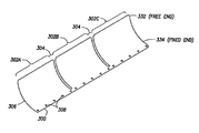
- FIG. 3A Illustrates an airflow damper 300 in accordance with embodiments of the disclosure.
- the airflow damper 300 is constructed of a resilient material such as stainless steel or polycarbonate.
- the term “resilient material” refers to a material that bends when more than a threshold amount of force is applied, but returns to its original shape once the threshold amount of force is removed.
- the resilient materials described herein should not significantly bend due to airflow (i.e., the force of airflow is less than the threshold amount of force), but should bend when a device is pushed against the resilient material (i.e., the force of pushing the device is greater than the threshold amount of force).
- the airflow damper 300 may be constructed as a one-piece body. Such construction is believed to offer reliability and cost advantages.
- the airflow damper 300 has three sections 302 A- 302 C divided by gaps 304 .
- the number of sections may Increase or decrease.
- the shape of the sections 302 A- 302 C is rectangular, although other shapes are possible.
- the purpose of each section is to emulate an airflow associated with a predetermined modular component, in other words, each section 302 A- 302 C does not necessarily block off all airflow and, instead, approximates whatever airflow exists when a predetermined modular component is installed.
- the sections 302 A- 302 C shown in FIG. 3A are approximately equal in size and shape, other embodiments could have sections which differ in size, shape, or direction.
- the airflow damper 300 has a default state and a device accommodation state.
- the free end 332 extends to restrict airflow.
- the free end 332 flattens to accommodate a device.
- the airflow damper 300 maintains a predetermined curvature 308 between the fixed end 334 and the free end 332 , while in the default state.
- the curvature 308 is substantially flattened to accommodate a device. Subsequently, upon removal of the device, the airflow damper 300 automatically returns to the default state due to the resilient material from which the airflow damper 300 is constructed.
- FIG. 38 illustrates a side view profile 350 of an airflow damper in accordance with embodiments.
- the fixed end 334 is shown to be substantially flat with respect to a mounting surface 352 .
- the free end 332 is angled to substantially block an airflow and to flatten when a device is pushed into the airflow damper.
- the free end 332 comprises a convex portion 336 that helps prevent the device from catching on the airflow damper during insertion or removal of the device.
- the free end 332 may comprises a bumper material that cushions or facilitates a device's movement along the free end 332 during insertion or removal of the device.
- the bumper material may comprise a plastic mold or coating.
- FIG. 4 illustrates an internal frame 400 of a modular electrical system with airflow dampers in accordance with embodiments of the disclosure.
- the frame 400 comprises an assembly of vertical sections 430 and horizontal sections 420 that form slots 440 to accommodate modular components such as power supply, servers, or other removable components, in at least some embodiments, each slot 440 is associated with a separate airflow cavity.
- slots 440 may physically support a modular component in a desired position without completely enclosing the modular component.
- an airflow cavity may correspond to one slot or multiple slots. Regardless of whether an airflow cavity corresponds to one slot or multiple slots, insertion or removal of modular components would undesirably change the airflow.
- two airflow dampers 300 bottom and 300 top are attached to the frame 400 .
- the fixed end 334 of the airflow damper 300 bottom to the bottom or to another horizontal section 420 of the frame 400 .
- the openings 308 can be used to rivet or otherwise fasten the fixed end 334 of the airflow damper 300 bottom to the bottom (or other horizontal section) of the frame 400 .
- the free end 332 of each section of the airflow damper 300 bottom extends to substantially block airflow through the lower slots 440 of the frame 400 when modular components are not installed in the slots 440 .
- airflow damper 300 bottom is positioned so that the gaps 304 line up with the vertical sections 430 of the frame 400 .
- the leftmost section of the airflow damper 300 bottom is shown in a flattened state or device accommodation state that automatically occurs upon insertion of a modular device into the corresponding slot.
- the fixed end 334 of the airflow damper 300 top attaches to the top (not shown) of the frame 400 .
- the openings 308 can be used to rivet or otherwise fasten the fixed end 334 of the airflow damper 300 top to the top or to another horizontal section 420 of the frame 400 .
- the free end 332 of each section of the airflow damper 300 top extends to substantially block airflow through the upper slots 440 of the frame 400 when modular components are not installed in the slots 440 .
- the gaps 304 between sections of the airflow damper 300 top line up with the vertical sections 430 of the frame 400 .
- airflow dampers 300 can be attached to a side section (i.e., vertical sections 430 ) of the frame 400 .
- the size of the gaps 304 between sections of an airflow damper 300 can be adjusted for different frame designs.
- airflow dampers 300 can be designed with or without the gaps 304 .
- the airflow damper 300 can include gaps 304 that will correspond with vertical or horizontal sections of a frame. If an airflow damper 300 is not available during frame assembly, the airflow damper 300 can later be added.
- separate single-section airflow dampers may be easier to Install than a single airflow damper with multiple sections separated by gaps 304 .
- FIG. 5 illustrates the modular electrical system 100 of FIG. 1 with airflow dampers 300 installed in accordance with embodiments of the disclosure.
- the power supply units 102 D- 102 F have been removed exposing airflow cavities.
- the airflow damper sections 302 A- 302 C are able to block or appropriately control airflow through the exposed airflow cavities.
- the power supply units 102 A- 102 G and the processor boards 104 A- 104 D may also be associated with corresponding airflow dampers or airflow damper sections which have been flattened due to Insertion of these devices Into the system 100 . Should one of the power supply units 102 A- 102 C or the processor boards 104 A- 104 D be removed, its corresponding airflow damper or airflow damper section would automatically extend into the exposed airflow cavity to appropriately control airflow for the system 100 .
Landscapes
- Engineering & Computer Science (AREA)
- General Engineering & Computer Science (AREA)
- Computer Hardware Design (AREA)
- Physics & Mathematics (AREA)
- Thermal Sciences (AREA)
- Microelectronics & Electronic Packaging (AREA)
- Chemical & Material Sciences (AREA)
- Combustion & Propulsion (AREA)
- Mechanical Engineering (AREA)
- Cooling Or The Like Of Electrical Apparatus (AREA)
Abstract
Description
Claims (6)
Priority Applications (1)
| Application Number | Priority Date | Filing Date | Title |
|---|---|---|---|
| US12/237,946 US8475246B2 (en) | 2008-09-25 | 2008-09-25 | Airflow damper that accommodates a device |
Applications Claiming Priority (1)
| Application Number | Priority Date | Filing Date | Title |
|---|---|---|---|
| US12/237,946 US8475246B2 (en) | 2008-09-25 | 2008-09-25 | Airflow damper that accommodates a device |
Publications (2)
| Publication Number | Publication Date |
|---|---|
| US20100073868A1 US20100073868A1 (en) | 2010-03-25 |
| US8475246B2 true US8475246B2 (en) | 2013-07-02 |
Family
ID=42037442
Family Applications (1)
| Application Number | Title | Priority Date | Filing Date |
|---|---|---|---|
| US12/237,946 Active 2032-05-02 US8475246B2 (en) | 2008-09-25 | 2008-09-25 | Airflow damper that accommodates a device |
Country Status (1)
| Country | Link |
|---|---|
| US (1) | US8475246B2 (en) |
Cited By (5)
| Publication number | Priority date | Publication date | Assignee | Title |
|---|---|---|---|---|
| US20120327598A1 (en) * | 2011-06-24 | 2012-12-27 | Fujitsu Limited | Electronic device housing device |
| US20150070829A1 (en) * | 2013-09-11 | 2015-03-12 | Hon Hai Precision Industry Co., Ltd. | Server with supporting bracket |
| US20150342095A1 (en) * | 2013-12-11 | 2015-11-26 | Hitachi, Ltd. | Storage subsystem and method for controlling the same |
| US10261275B2 (en) | 2015-05-11 | 2019-04-16 | Hewlett Packard Enterprise Development Lp | Baffle with optical connector |
| US12289867B2 (en) | 2021-05-04 | 2025-04-29 | Vertiv Corporation | Electronic equipment cabinets with configurable air plenums |
Families Citing this family (9)
| Publication number | Priority date | Publication date | Assignee | Title |
|---|---|---|---|---|
| US9788455B1 (en) * | 2007-06-14 | 2017-10-10 | Switch, Ltd. | Electronic equipment data center or co-location facility designs and methods of making and using the same |
| US7843683B2 (en) * | 2009-02-26 | 2010-11-30 | International Business Machines Corporation | Airflow bypass damper |
| CN102023683B (en) * | 2009-09-11 | 2013-08-28 | 鸿富锦精密工业(深圳)有限公司 | Server cabinet |
| US20110228475A1 (en) * | 2010-03-17 | 2011-09-22 | International Business Machines Corporation | Enclosure with concurrently maintainable field replaceable units |
| CN102541222A (en) * | 2010-12-31 | 2012-07-04 | 鸿富锦精密工业(深圳)有限公司 | Rack-mounted server system |
| US8982554B2 (en) * | 2012-12-26 | 2015-03-17 | Oracle International Corporation | Airflow management system for cabinet having field replaceable units |
| US10334759B2 (en) * | 2013-11-26 | 2019-06-25 | Panduit Corp. | Universal inlet duct system for side air intake equipment |
| US9443560B2 (en) * | 2014-11-03 | 2016-09-13 | Western Digital Technologies, Inc. | Server with storage drive cooling system |
| US9877415B2 (en) | 2016-03-08 | 2018-01-23 | Western Digital Technologies, Inc. | Cold storage server with heat dissipation |
Citations (5)
| Publication number | Priority date | Publication date | Assignee | Title |
|---|---|---|---|---|
| US20080026625A1 (en) * | 2006-07-05 | 2008-01-31 | International Business Machines Corporation | Connector for Adjacent Devices |
| US20090019680A1 (en) * | 2007-07-17 | 2009-01-22 | Krohn Kenneth P | Variable joining device and method for its use |
| US20090027852A1 (en) * | 2007-07-26 | 2009-01-29 | Roesner Arlen L | Airflow redirction device |
| US7589973B2 (en) * | 2007-09-05 | 2009-09-15 | Sun Microsystems, Inc. | Air duct flow optimization device |
| US20090233537A1 (en) * | 2008-03-14 | 2009-09-17 | Inventec Corporation | Air baffle and calculation method of deformational stress thereof |
-
2008
- 2008-09-25 US US12/237,946 patent/US8475246B2/en active Active
Patent Citations (5)
| Publication number | Priority date | Publication date | Assignee | Title |
|---|---|---|---|---|
| US20080026625A1 (en) * | 2006-07-05 | 2008-01-31 | International Business Machines Corporation | Connector for Adjacent Devices |
| US20090019680A1 (en) * | 2007-07-17 | 2009-01-22 | Krohn Kenneth P | Variable joining device and method for its use |
| US20090027852A1 (en) * | 2007-07-26 | 2009-01-29 | Roesner Arlen L | Airflow redirction device |
| US7589973B2 (en) * | 2007-09-05 | 2009-09-15 | Sun Microsystems, Inc. | Air duct flow optimization device |
| US20090233537A1 (en) * | 2008-03-14 | 2009-09-17 | Inventec Corporation | Air baffle and calculation method of deformational stress thereof |
Cited By (7)
| Publication number | Priority date | Publication date | Assignee | Title |
|---|---|---|---|---|
| US20120327598A1 (en) * | 2011-06-24 | 2012-12-27 | Fujitsu Limited | Electronic device housing device |
| US8824137B2 (en) * | 2011-06-24 | 2014-09-02 | Fujitsu Limited | Electronic device housing device |
| US20150070829A1 (en) * | 2013-09-11 | 2015-03-12 | Hon Hai Precision Industry Co., Ltd. | Server with supporting bracket |
| US20150342095A1 (en) * | 2013-12-11 | 2015-11-26 | Hitachi, Ltd. | Storage subsystem and method for controlling the same |
| US9398728B2 (en) * | 2013-12-11 | 2016-07-19 | Hitachi, Ltd. | Storage subsystem and method for controlling the same |
| US10261275B2 (en) | 2015-05-11 | 2019-04-16 | Hewlett Packard Enterprise Development Lp | Baffle with optical connector |
| US12289867B2 (en) | 2021-05-04 | 2025-04-29 | Vertiv Corporation | Electronic equipment cabinets with configurable air plenums |
Also Published As
| Publication number | Publication date |
|---|---|
| US20100073868A1 (en) | 2010-03-25 |
Similar Documents
| Publication | Publication Date | Title |
|---|---|---|
| US8475246B2 (en) | Airflow damper that accommodates a device | |
| US5544006A (en) | Computer chassis having flexible card guide for expansion card insertion and removal | |
| US7684181B2 (en) | Mounting apparatus for storage device | |
| CN101669079B (en) | Drive carrier for computer systems | |
| US8075248B2 (en) | Fan assembly | |
| US7852637B2 (en) | Bi-positional expansion card retainer | |
| CN201084085Y (en) | Fan installation apparatus | |
| US8136576B2 (en) | Vibration isolation system for synthetic jet devices | |
| US8047780B2 (en) | Assembled fan frame | |
| US8068341B2 (en) | Electronic device with expansion card and holder | |
| US7304841B2 (en) | Connection arrangement of blade server | |
| CN103562815B (en) | Mounting frame and support for mounting components of a computing system | |
| US6424527B1 (en) | Computer board support and heat sink retention apparatus | |
| US8811009B2 (en) | Air duct and computer system with air duct | |
| US20120147545A1 (en) | Mounting apparatus for data storage devices | |
| US7839631B2 (en) | Computer enclosure with airflow-guiding device | |
| CN1356018A (en) | Solid part of heat sink of electronic component | |
| US8282345B2 (en) | Heat dissipating device | |
| US20130163191A1 (en) | Computer system with air duct | |
| US20130315728A1 (en) | Fixing device for fan | |
| CN101872225A (en) | Paste-type deflector and motherboard using the deflector | |
| US11419224B1 (en) | Electronic assembly | |
| CN102215657A (en) | Fan fixing device | |
| US8711557B2 (en) | Support tray for server | |
| CN105557079A (en) | Server insert for a server rack |
Legal Events
| Date | Code | Title | Description |
|---|---|---|---|
| AS | Assignment |
Owner name: HEWLETT-PACKARD DEVELOPMENT COMPANY, L.P.,TEXAS Free format text: ASSIGNMENT OF ASSIGNORS INTEREST;ASSIGNORS:MAYER, DAVE;RUBENS, PAUL;SIGNING DATES FROM 20080424 TO 20080429;REEL/FRAME:022977/0967 Owner name: HEWLETT-PACKARD DEVELOPMENT COMPANY, L.P., TEXAS Free format text: ASSIGNMENT OF ASSIGNORS INTEREST;ASSIGNORS:MAYER, DAVE;RUBENS, PAUL;SIGNING DATES FROM 20080424 TO 20080429;REEL/FRAME:022977/0967 |
|
| STCF | Information on status: patent grant |
Free format text: PATENTED CASE |
|
| AS | Assignment |
Owner name: HEWLETT PACKARD ENTERPRISE DEVELOPMENT LP, TEXAS Free format text: ASSIGNMENT OF ASSIGNORS INTEREST;ASSIGNOR:HEWLETT-PACKARD DEVELOPMENT COMPANY, L.P.;REEL/FRAME:037079/0001 Effective date: 20151027 |
|
| FPAY | Fee payment |
Year of fee payment: 4 |
|
| MAFP | Maintenance fee payment |
Free format text: PAYMENT OF MAINTENANCE FEE, 8TH YEAR, LARGE ENTITY (ORIGINAL EVENT CODE: M1552); ENTITY STATUS OF PATENT OWNER: LARGE ENTITY Year of fee payment: 8 |
|
| MAFP | Maintenance fee payment |
Free format text: PAYMENT OF MAINTENANCE FEE, 12TH YEAR, LARGE ENTITY (ORIGINAL EVENT CODE: M1553); ENTITY STATUS OF PATENT OWNER: LARGE ENTITY Year of fee payment: 12 |