US8464426B2 - Gas turbine engine airfoil - Google Patents
Gas turbine engine airfoil Download PDFInfo
- Publication number
- US8464426B2 US8464426B2 US13/437,040 US201213437040A US8464426B2 US 8464426 B2 US8464426 B2 US 8464426B2 US 201213437040 A US201213437040 A US 201213437040A US 8464426 B2 US8464426 B2 US 8464426B2
- Authority
- US
- United States
- Prior art keywords
- airfoil
- angle
- rotor blade
- gas turbine
- dihedral angle
- Prior art date
- Legal status (The legal status is an assumption and is not a legal conclusion. Google has not performed a legal analysis and makes no representation as to the accuracy of the status listed.)
- Active
Links
Images


Classifications
-
- F—MECHANICAL ENGINEERING; LIGHTING; HEATING; WEAPONS; BLASTING
- F01—MACHINES OR ENGINES IN GENERAL; ENGINE PLANTS IN GENERAL; STEAM ENGINES
- F01D—NON-POSITIVE DISPLACEMENT MACHINES OR ENGINES, e.g. STEAM TURBINES
- F01D5/00—Blades; Blade-carrying members; Heating, heat-insulating, cooling or antivibration means on the blades or the members
- F01D5/12—Blades
- F01D5/14—Form or construction
- F01D5/141—Shape, i.e. outer, aerodynamic form
-
- F—MECHANICAL ENGINEERING; LIGHTING; HEATING; WEAPONS; BLASTING
- F01—MACHINES OR ENGINES IN GENERAL; ENGINE PLANTS IN GENERAL; STEAM ENGINES
- F01D—NON-POSITIVE DISPLACEMENT MACHINES OR ENGINES, e.g. STEAM TURBINES
- F01D5/00—Blades; Blade-carrying members; Heating, heat-insulating, cooling or antivibration means on the blades or the members
- F01D5/12—Blades
-
- F—MECHANICAL ENGINEERING; LIGHTING; HEATING; WEAPONS; BLASTING
- F04—POSITIVE - DISPLACEMENT MACHINES FOR LIQUIDS; PUMPS FOR LIQUIDS OR ELASTIC FLUIDS
- F04D—NON-POSITIVE-DISPLACEMENT PUMPS
- F04D29/00—Details, component parts, or accessories
- F04D29/26—Rotors specially for elastic fluids
- F04D29/32—Rotors specially for elastic fluids for axial flow pumps
- F04D29/321—Rotors specially for elastic fluids for axial flow pumps for axial flow compressors
- F04D29/324—Blades
-
- F—MECHANICAL ENGINEERING; LIGHTING; HEATING; WEAPONS; BLASTING
- F05—INDEXING SCHEMES RELATING TO ENGINES OR PUMPS IN VARIOUS SUBCLASSES OF CLASSES F01-F04
- F05D—INDEXING SCHEME FOR ASPECTS RELATING TO NON-POSITIVE-DISPLACEMENT MACHINES OR ENGINES, GAS-TURBINES OR JET-PROPULSION PLANTS
- F05D2240/00—Components
- F05D2240/20—Rotors
- F05D2240/30—Characteristics of rotor blades, i.e. of any element transforming dynamic fluid energy to or from rotational energy and being attached to a rotor
- F05D2240/301—Cross-sectional characteristics
-
- Y—GENERAL TAGGING OF NEW TECHNOLOGICAL DEVELOPMENTS; GENERAL TAGGING OF CROSS-SECTIONAL TECHNOLOGIES SPANNING OVER SEVERAL SECTIONS OF THE IPC; TECHNICAL SUBJECTS COVERED BY FORMER USPC CROSS-REFERENCE ART COLLECTIONS [XRACs] AND DIGESTS
- Y10—TECHNICAL SUBJECTS COVERED BY FORMER USPC
- Y10T—TECHNICAL SUBJECTS COVERED BY FORMER US CLASSIFICATION
- Y10T29/00—Metal working
- Y10T29/49—Method of mechanical manufacture
- Y10T29/49316—Impeller making
- Y10T29/4932—Turbomachine making
- Y10T29/49321—Assembling individual fluid flow interacting members, e.g., blades, vanes, buckets, on rotary support member
-
- Y—GENERAL TAGGING OF NEW TECHNOLOGICAL DEVELOPMENTS; GENERAL TAGGING OF CROSS-SECTIONAL TECHNOLOGIES SPANNING OVER SEVERAL SECTIONS OF THE IPC; TECHNICAL SUBJECTS COVERED BY FORMER USPC CROSS-REFERENCE ART COLLECTIONS [XRACs] AND DIGESTS
- Y10—TECHNICAL SUBJECTS COVERED BY FORMER USPC
- Y10T—TECHNICAL SUBJECTS COVERED BY FORMER US CLASSIFICATION
- Y10T29/00—Metal working
- Y10T29/49—Method of mechanical manufacture
- Y10T29/49316—Impeller making
- Y10T29/49336—Blade making
- Y10T29/49337—Composite blade
Definitions
- This disclosure generally relates to a gas turbine engine, and more particularly to rotor blades that improve gas turbine engine performance.
- Gas turbine engines such as turbofan gas turbine engines, typically include a fan section, a compressor section, a combustor section and a turbine section. During operation, air is pressurized in the compressor section and mixed with fuel in the combustor section for generating hot combustion gases. The hot combustion gases flow through the turbine section which extracts energy from the hot combustion gases to power the compressor section and drive the fan section.
- Axial-flow compressors utilize multiple stages to obtain the pressure levels needed to achieve desired thermodynamic cycle goals.
- a typical compressor stage consists of a row of moving airfoils (called rotor blades) and a row of stationary airfoils (called stator vanes).
- stator vanes The flow path of the axial-flow compressor section decreases in cross-sectional area in the direction of flow to reduce the volume of air as compression progresses through the compressor section. That is, each subsequent stage of the axial flow compressor decreases in size to maximize the performance of the compressor section.
- Tip clearance flow is defined as the amount of airflow that escapes between the tip of the rotor blade and the adjacent shroud. Tip clearance flow reduces the ability of the compressor section to sustain pressure rise and may have a negative impact on stall margin (i.e., the point at which the compressor section can no longer sustain an increase in pressure such that the gas turbine engine stalls).
- blade performance and operability of the gas turbine engine are highly sensitive to the lower spans (i.e., decreased size) of the rotor blades and the corresponding high clearance to span ratios.
- prior rotor blade airfoil designs have not adequately alleviated the negative effects caused by tip clearance flow.
- a method of designing an airfoil for a gas turbine engine can include localizing a sweep angle at a leading edge of a tip region of the airfoil, and localizing a dihedral angle at the tip region of the airfoil.
- the dihedral angle can be applied by translating the airfoil in direction normal to a chord of the airfoil.
- the sweep angle can include a forward sweep angle.
- the step of localizing the sweep angle can include displacing a plurality of airfoil sections of the airfoil parallel to the chord relative to a base-line rotor blade design.
- the dihedral angle can include a positive dihedral angle.
- the step of localizing the dihedral angle can include displacing a plurality of airfoil sections of the airfoil tangentially to the chord relative to a base-line rotor blade design.
- the sweep angle and the dihedral angle can be extended over a distance of the airfoil equivalent to about 10% to about 40% of a span of the airfoil.
- the sweep angle and the dihedral angle can be extended from an outer edge of the tip region radially inward along a radial axis over a distance equal to about 10% to about 40% of the span.
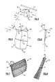
- FIG. 1 is a cross-sectional view of an example gas turbine engine
- FIG. 2 illustrates a portion of a compressor section of the example gas turbine engine illustrated in FIG. 1 ;
- FIG. 3 illustrates a schematic view of a rotor blade according to the present disclosure
- FIG. 4 illustrates another view of the example rotor blade illustrated in FIG. 3 ;
- FIG. 5 illustrates an airfoil designed having a sweep angle S and a dihedral angle D
- FIG. 6 illustrates a sectional view through section 6 - 6 of FIG. 5 ;
- FIG. 7 illustrates yet another view of the example rotor blade having a redesigned tip region merged relative to a base-line design of the rotor blade
- FIG. 8 illustrates another view of the rotor blade illustrated in FIG. 5 as viewed from a leading edge of the rotor blade.
- FIG. 1 illustrates an example gas turbine engine 10 that includes a fan 12 , a compressor section 14 , a combustor section 16 and a turbine section 18 .
- the gas turbine engine 10 is defined about an engine centerline axis A about which the various engine sections rotate.
- air is drawn into the gas turbine engine 10 by the fan 12 and flows through the compressor section 14 to pressurize the airflow.
- Fuel is mixed with the pressurized air and combusted within the combustor 16 .
- the combustion gases are discharged through the turbine section 18 which extracts energy therefrom for powering the compressor section 14 and the fan 12 .
- the gas turbine engine 10 is a turbofan gas turbine engine. It should be understood, however, that the features and illustrations presented within this disclosure are not limited to a turbofan gas turbine engine. That is, the present disclosure is applicable to any engine architecture.
- FIG. 2 schematically illustrates a portion of the compressor section 14 of the gas turbine engine 10 .
- the compressor section 14 is an axial-flow compressor.
- Compressor section 14 includes a plurality of compression stages including alternating rows of rotor blades 30 and stator blades 32 .
- the rotor blades 30 rotate about the engine centerline axis A in a known manner to increase the velocity and pressure level of the airflow communicated through the compressor section 14 .
- the stationary stator blades 32 convert the velocity of the airflow into pressure, and turn the airflow in a desired direction to prepare the airflow for the next set of rotor blades 30 .
- the rotor blades 30 are partially housed by a shroud assembly 34 (i.e., outer case).
- a gap 36 extends between a tip region 38 of each rotor blade 30 to provide clearance for the rotating rotor blades 30 .
- FIGS. 3 and 4 illustrate an example rotor blade 30 that includes unique design elements localized at tip region 38 for reducing the detrimental effect of tip clearance flow.
- Tip clearance flow is defined as the amount of airflow that escapes through the gap 36 between the tip region 38 of the rotor blade 30 and the shroud assembly 34 .
- the rotor blade 30 includes an airfoil 40 having a leading edge 42 and a trailing edge 44 .
- a chord 46 of the airfoil 40 extends between the leading edge 42 and the trailing edge 44 .
- a span 48 of the airfoil 40 extends between a root 50 and the tip region 38 of the rotor blade 30 .
- the root 50 of the rotor blade 30 is adjacent to a platform 52 that connects the rotor blade 30 to a rotating drum or disk (not shown) in a known manner.
- the airfoil 40 of the rotor blade 30 also includes a suction surface 54 and an opposite pressure surface 56 .
- the suction surface 54 is a generally convex surface and the pressure surface 56 is a generally concave surface.
- the suction surface 54 and the pressure surface 56 are designed conventionally to pressurize the airflow as airflow F is communicated from an upstream direction U to a downstream direction DN.
- the airflow F flows in an axial direction X that is parallel to the longitudinal centerline axis A of the gas turbine engine A.
- the rotor blade 30 rotates in a rotational direction (circumferential) Y about the engine centerline axis A.
- the span 48 of the airfoil 40 is positioned along a radial axis Z of the rotor blade 30 .
- the example rotor blade 30 includes a sweep angle S (See FIG. 3 ) and a dihedral angle D (See FIG. 4 ) that are each localized relative to the tip region 38 of the rotor blade 30 .
- the term “localized” as utilized in this disclosure is intended to define the sweep angle S and the dihedral angle D at a specific portion of the airfoil 40 , as is further discussed below.
- the sweep angle S and the dihedral angle D are disclosed herein with respect to a rotor blade, it should be understood that other components of the gas turbine engine 10 may benefit from similar aerodynamic improvements as those illustrated with respect to the rotor blade 30 .
- the sweep angle S is defined as the angle between the velocity vector V of incoming flow relative to the airfoil 40 and a line tangent to the leading edge 42 of the airfoil 40 .
- the sweep angle S is a forward sweep angle. Forward sweep usually involves translating an airfoil section at a higher radius forward (opposite to incoming airflow) along the direction of the chord 46 .
- the dihedral angle D is defined as the angle between the shroud assembly 34 and the airfoil 40 .
- the dihedral in the tip region 38 of the airfoil 40 is controlled by translating the airfoil 40 in a direction perpendicular to the chord 46 .
- a measure of the dihedral angle D is performed at the center of gravity C of the airfoil 40 .
- the dihedral angle D is a positive dihedral angle. Positive dihedral increases the angle between the suction surface 54 of the airfoil 40 and an interior surface 58 of the shroud assembly 34 . That is, positive dihedral angle results in the suction surface 54 pointing down relative to the shroud assembly 34 .
- the suction surface 54 forms an acute dihedral angle D relative to the shroud assembly 34 .
- the amount of sweep S and dihedral D included on the rotor blade 30 is defined at the tip region 38 of the rotor blade 30 and merged back to a baseline geometry (see FIGS. 7 and 8 ).
- the sweep angle S and the dihedral angle D extend over a distance of the airfoil 40 that is equivalent to about 10% to about 40% of the span 48 of the rotor blade 30 . That is, the sweep S and dihedral D are positioned at a distance from an outer edge 39 of the tip region 38 radially inward along radial axis Z by about 10% to about 40% of the total span 48 of the airfoil 40 .
- the term “about” as utilized in this disclosure is defined to include general variations in tolerances as would be understood by a person of ordinary skill in the art having the benefit of this disclosure.
- FIGS. 7 and 8 illustrate the example rotor blade 30 superimposed over a base-line design rotor blade (shown in shaded portions).
- the base-line design rotor blade represents a blade having sweep and dihedral as a result of stacking airfoil sections in a conventional way.
- a conventional stacking is such that the center of gravity of airfoil sections are close to being radial with offset as a result of minimizing stress caused by centrifugal force acting on the airfoil when the rotor is rotating.
- a plurality of airfoil sections 60 of the rotor blade are tangentially and axially restacked relative to the base-line design rotor blade to provide tip region 38 localized forward sweep S and positive dihedral D, for example.
- the amount of sweep S and dihedral D and the corresponding tangential and axial offsets are defined at the tip region 38 and merged back to the base-line design rotor blade over a distance equivalent to about 10% to about 40% of the span 48 of the rotor blade 30 , in one example.
Landscapes
- Engineering & Computer Science (AREA)
- Mechanical Engineering (AREA)
- General Engineering & Computer Science (AREA)
- Physics & Mathematics (AREA)
- Fluid Mechanics (AREA)
- Structures Of Non-Positive Displacement Pumps (AREA)
- Turbine Rotor Nozzle Sealing (AREA)
Abstract
Description
Claims (7)
Priority Applications (2)
| Application Number | Priority Date | Filing Date | Title |
|---|---|---|---|
| US13/437,040 US8464426B2 (en) | 2008-12-17 | 2012-04-02 | Gas turbine engine airfoil |
| US13/898,672 US8807951B2 (en) | 2008-12-17 | 2013-05-21 | Gas turbine engine airfoil |
Applications Claiming Priority (2)
| Application Number | Priority Date | Filing Date | Title |
|---|---|---|---|
| US12/336,610 US8167567B2 (en) | 2008-12-17 | 2008-12-17 | Gas turbine engine airfoil |
| US13/437,040 US8464426B2 (en) | 2008-12-17 | 2012-04-02 | Gas turbine engine airfoil |
Related Parent Applications (1)
| Application Number | Title | Priority Date | Filing Date |
|---|---|---|---|
| US12/336,610 Division US8167567B2 (en) | 2008-12-17 | 2008-12-17 | Gas turbine engine airfoil |
Related Child Applications (1)
| Application Number | Title | Priority Date | Filing Date |
|---|---|---|---|
| US13/898,672 Continuation US8807951B2 (en) | 2008-12-17 | 2013-05-21 | Gas turbine engine airfoil |
Publications (2)
| Publication Number | Publication Date |
|---|---|
| US20120192421A1 US20120192421A1 (en) | 2012-08-02 |
| US8464426B2 true US8464426B2 (en) | 2013-06-18 |
Family
ID=41581129
Family Applications (3)
| Application Number | Title | Priority Date | Filing Date |
|---|---|---|---|
| US12/336,610 Active 2030-09-26 US8167567B2 (en) | 2008-12-17 | 2008-12-17 | Gas turbine engine airfoil |
| US13/437,040 Active US8464426B2 (en) | 2008-12-17 | 2012-04-02 | Gas turbine engine airfoil |
| US13/898,672 Active US8807951B2 (en) | 2008-12-17 | 2013-05-21 | Gas turbine engine airfoil |
Family Applications Before (1)
| Application Number | Title | Priority Date | Filing Date |
|---|---|---|---|
| US12/336,610 Active 2030-09-26 US8167567B2 (en) | 2008-12-17 | 2008-12-17 | Gas turbine engine airfoil |
Family Applications After (1)
| Application Number | Title | Priority Date | Filing Date |
|---|---|---|---|
| US13/898,672 Active US8807951B2 (en) | 2008-12-17 | 2013-05-21 | Gas turbine engine airfoil |
Country Status (2)
| Country | Link |
|---|---|
| US (3) | US8167567B2 (en) |
| EP (1) | EP2199543B1 (en) |
Cited By (32)
| Publication number | Priority date | Publication date | Assignee | Title |
|---|---|---|---|---|
| US9140127B2 (en) | 2014-02-19 | 2015-09-22 | United Technologies Corporation | Gas turbine engine airfoil |
| US9163517B2 (en) | 2014-02-19 | 2015-10-20 | United Technologies Corporation | Gas turbine engine airfoil |
| US9347323B2 (en) | 2014-02-19 | 2016-05-24 | United Technologies Corporation | Gas turbine engine airfoil total chord relative to span |
| US9353628B2 (en) | 2014-02-19 | 2016-05-31 | United Technologies Corporation | Gas turbine engine airfoil |
| US9567858B2 (en) | 2014-02-19 | 2017-02-14 | United Technologies Corporation | Gas turbine engine airfoil |
| US9599064B2 (en) | 2014-02-19 | 2017-03-21 | United Technologies Corporation | Gas turbine engine airfoil |
| US9605542B2 (en) | 2014-02-19 | 2017-03-28 | United Technologies Corporation | Gas turbine engine airfoil |
| US9732762B2 (en) | 2014-08-27 | 2017-08-15 | Pratt & Whitney Canada Corp. | Compressor airfoil |
| US9765795B2 (en) | 2014-08-27 | 2017-09-19 | Pratt & Whitney Canada Corp. | Compressor rotor airfoil |
| US20180209335A1 (en) * | 2017-01-23 | 2018-07-26 | General Electric Company | Interdigitated counter rotating turbine system and method of operation |
| US20180209336A1 (en) * | 2017-01-23 | 2018-07-26 | General Electric Company | Three spool gas turbine engine with interdigitated turbine section |
| US10036257B2 (en) | 2014-02-19 | 2018-07-31 | United Technologies Corporation | Gas turbine engine airfoil |
| US10330111B2 (en) | 2014-04-02 | 2019-06-25 | United Technologies Corporation | Gas turbine engine airfoil |
| US10352331B2 (en) | 2014-02-19 | 2019-07-16 | United Technologies Corporation | Gas turbine engine airfoil |
| US20190234217A1 (en) * | 2018-02-01 | 2019-08-01 | Honda Motor Co., Ltd. | Fan blade and method for determining shape of fan blade |
| US10385866B2 (en) | 2014-02-19 | 2019-08-20 | United Technologies Corporation | Gas turbine engine airfoil |
| US10393139B2 (en) | 2014-02-19 | 2019-08-27 | United Technologies Corporation | Gas turbine engine airfoil |
| US10422226B2 (en) | 2014-02-19 | 2019-09-24 | United Technologies Corporation | Gas turbine engine airfoil |
| US10443390B2 (en) | 2014-08-27 | 2019-10-15 | Pratt & Whitney Canada Corp. | Rotary airfoil |
| US10465702B2 (en) | 2014-02-19 | 2019-11-05 | United Technologies Corporation | Gas turbine engine airfoil |
| US10495106B2 (en) | 2014-02-19 | 2019-12-03 | United Technologies Corporation | Gas turbine engine airfoil |
| US10502229B2 (en) | 2014-02-19 | 2019-12-10 | United Technologies Corporation | Gas turbine engine airfoil |
| US10519971B2 (en) | 2014-02-19 | 2019-12-31 | United Technologies Corporation | Gas turbine engine airfoil |
| US10557477B2 (en) | 2014-02-19 | 2020-02-11 | United Technologies Corporation | Gas turbine engine airfoil |
| US10570915B2 (en) | 2014-02-19 | 2020-02-25 | United Technologies Corporation | Gas turbine engine airfoil |
| US10570916B2 (en) | 2014-02-19 | 2020-02-25 | United Technologies Corporation | Gas turbine engine airfoil |
| US10584715B2 (en) | 2014-02-19 | 2020-03-10 | United Technologies Corporation | Gas turbine engine airfoil |
| US10590775B2 (en) | 2014-02-19 | 2020-03-17 | United Technologies Corporation | Gas turbine engine airfoil |
| US10605259B2 (en) | 2014-02-19 | 2020-03-31 | United Technologies Corporation | Gas turbine engine airfoil |
| US11428160B2 (en) | 2020-12-31 | 2022-08-30 | General Electric Company | Gas turbine engine with interdigitated turbine and gear assembly |
| EP4269012A1 (en) | 2022-04-28 | 2023-11-01 | Rolls-Royce Corporation | Dual head pecm |
| US20250305447A1 (en) * | 2024-03-27 | 2025-10-02 | General Electric Company | Compact core arrangement for high bypass ratio gas turbine engine architecture |
Families Citing this family (40)
| Publication number | Priority date | Publication date | Assignee | Title |
|---|---|---|---|---|
| WO2012053024A1 (en) * | 2010-10-18 | 2012-04-26 | 株式会社 日立製作所 | Transonic blade |
| FR2969230B1 (en) * | 2010-12-15 | 2014-11-21 | Snecma | COMPRESSOR BLADE WITH IMPROVED STACKING LAW |
| US9309769B2 (en) * | 2010-12-28 | 2016-04-12 | Rolls-Royce Corporation | Gas turbine engine airfoil shaped component |
| JP5703750B2 (en) * | 2010-12-28 | 2015-04-22 | 株式会社Ihi | Fan blade and fan |
| US8684698B2 (en) * | 2011-03-25 | 2014-04-01 | General Electric Company | Compressor airfoil with tip dihedral |
| US8702398B2 (en) | 2011-03-25 | 2014-04-22 | General Electric Company | High camber compressor rotor blade |
| FR2981118B1 (en) * | 2011-10-07 | 2016-01-29 | Snecma | MONOBLOC AUBING DISC WITH AUBES WITH ADAPTED FOOT PROFILE |
| FR2981396A1 (en) * | 2011-10-13 | 2013-04-19 | Snecma | TURBOMACHINE STATOR VANE COMPRISING A BOMBED PORTION |
| FR2983234B1 (en) | 2011-11-29 | 2014-01-17 | Snecma | AUBE FOR TURBOMACHINE MONOBLOC AUBING DISK |
| US9017036B2 (en) * | 2012-02-29 | 2015-04-28 | United Technologies Corporation | High order shaped curve region for an airfoil |
| FR2993323B1 (en) * | 2012-07-12 | 2014-08-15 | Snecma | TURBOMACHINE DAWN HAVING A PROFIL CONFIGURED TO OBTAIN IMPROVED AERODYNAMIC AND MECHANICAL PROPERTIES |
| WO2014031160A1 (en) * | 2012-08-22 | 2014-02-27 | United Technologies Corporation | Compliant cantilevered airfoil |
| FR2999151B1 (en) * | 2012-12-07 | 2017-01-27 | Snecma | PROPELLER BLADE FOR TURBOMACHINE |
| US9845683B2 (en) | 2013-01-08 | 2017-12-19 | United Technology Corporation | Gas turbine engine rotor blade |
| US10233758B2 (en) | 2013-10-08 | 2019-03-19 | United Technologies Corporation | Detuning trailing edge compound lean contour |
| EP2921647A1 (en) | 2014-03-20 | 2015-09-23 | Alstom Technology Ltd | Gas turbine blade comprising bended leading and trailing edges |
| US10060263B2 (en) | 2014-09-15 | 2018-08-28 | United Technologies Corporation | Incidence-tolerant, high-turning fan exit stator |
| US20160201468A1 (en) * | 2015-01-13 | 2016-07-14 | General Electric Company | Turbine airfoil |
| EP3081751B1 (en) * | 2015-04-14 | 2020-10-21 | Ansaldo Energia Switzerland AG | Cooled airfoil and method for manufacturing said airfoil |
| GB201508763D0 (en) | 2015-05-22 | 2015-07-01 | Rolls Royce Plc | Rotary blade manufacturing method |
| FR3040071B1 (en) * | 2015-08-11 | 2020-03-27 | Safran Aircraft Engines | TURBOMACHINE ROTOR DAWN |
| US20170152019A1 (en) * | 2015-11-30 | 2017-06-01 | General Electric Company | Airfoil for a rotary machine including a propellor assembly |
| US10414486B2 (en) | 2015-11-30 | 2019-09-17 | General Electric Company | Airfoil for a rotary machine including a propellor assembly |
| US10221859B2 (en) * | 2016-02-08 | 2019-03-05 | General Electric Company | Turbine engine compressor blade |
| EP3273006B1 (en) | 2016-07-21 | 2019-07-03 | United Technologies Corporation | Alternating starter use during multi-engine motoring |
| EP3273016B1 (en) | 2016-07-21 | 2020-04-01 | United Technologies Corporation | Multi-engine coordination during gas turbine engine motoring |
| US10618666B2 (en) | 2016-07-21 | 2020-04-14 | United Technologies Corporation | Pre-start motoring synchronization for multiple engines |
| US10384791B2 (en) | 2016-07-21 | 2019-08-20 | United Technologies Corporation | Cross engine coordination during gas turbine engine motoring |
| US10787968B2 (en) | 2016-09-30 | 2020-09-29 | Raytheon Technologies Corporation | Gas turbine engine motoring with starter air valve manual override |
| US10443543B2 (en) * | 2016-11-04 | 2019-10-15 | United Technologies Corporation | High compressor build clearance reduction |
| US10823079B2 (en) | 2016-11-29 | 2020-11-03 | Raytheon Technologies Corporation | Metered orifice for motoring of a gas turbine engine |
| CN108223016B (en) * | 2016-12-14 | 2021-10-22 | 通用电气公司 | Airfoils for rotary machines including thruster assemblies |
| US20190106989A1 (en) * | 2017-10-09 | 2019-04-11 | United Technologies Corporation | Gas turbine engine airfoil |
| DE102018202888A1 (en) * | 2018-02-26 | 2019-08-29 | MTU Aero Engines AG | Guide blade for the hot gas duct of a turbomachine |
| US10837286B2 (en) | 2018-10-16 | 2020-11-17 | General Electric Company | Frangible gas turbine engine airfoil with chord reduction |
| GB2574493A (en) * | 2019-01-22 | 2019-12-11 | Rolls Royce Plc | Stacking of rotor blade aerofoil sections to adjust resonant frequencies |
| DE102019220493A1 (en) * | 2019-12-20 | 2021-06-24 | MTU Aero Engines AG | Gas turbine blade |
| DE102021130522A1 (en) * | 2021-11-22 | 2023-05-25 | MTU Aero Engines AG | Blade for a turbomachine and turbomachine, having at least one blade |
| US12571320B2 (en) * | 2024-06-06 | 2026-03-10 | Honeywell International Inc | Turbine blade tip geometry system and method for gas turbine engine |
| US12509988B2 (en) | 2024-06-14 | 2025-12-30 | Pratt & Whitney Canada Corp. | Turbine engine airfoil |
Citations (22)
| Publication number | Priority date | Publication date | Assignee | Title |
|---|---|---|---|---|
| US4880355A (en) | 1987-06-29 | 1989-11-14 | Aerospatiale Societe Nationale Industrielle | Blade with curved end for a rotary airfoil of an aircraft |
| US4979698A (en) | 1988-07-07 | 1990-12-25 | Paul Lederman | Rotor system for winged aircraft |
| US5088892A (en) | 1990-02-07 | 1992-02-18 | United Technologies Corporation | Bowed airfoil for the compression section of a rotary machine |
| US5137427A (en) | 1990-12-20 | 1992-08-11 | United Technologies Corporation | Quiet tail rotor |
| US5199851A (en) | 1990-10-24 | 1993-04-06 | Westland Helicopters Ltd. | Helicopter rotor blades |
| US5332362A (en) | 1992-04-09 | 1994-07-26 | Societe Anonyme Dite: Eurocopter France | Blade for aircraft rotary wings, with swept-back tip |
| US5393199A (en) | 1992-07-22 | 1995-02-28 | Valeo Thermique Moteur | Fan having a blade structure for reducing noise |
| US5685696A (en) | 1994-06-10 | 1997-11-11 | Ebara Corporation | Centrifugal or mixed flow turbomachines |
| US5730583A (en) | 1994-09-29 | 1998-03-24 | Valeo Thermique Moteur | Axial flow fan blade structure |
| US5992793A (en) | 1996-01-04 | 1999-11-30 | Gkn Westland Helicopters Limited | Aerofoil |
| US6071077A (en) | 1996-04-09 | 2000-06-06 | Rolls-Royce Plc | Swept fan blade |
| US6331100B1 (en) | 1999-12-06 | 2001-12-18 | General Electric Company | Doubled bowed compressor airfoil |
| US6368061B1 (en) | 1999-11-30 | 2002-04-09 | Siemens Automotive, Inc. | High efficiency and low weight axial flow fan |
| US6899526B2 (en) | 2003-08-05 | 2005-05-31 | General Electric Company | Counterstagger compressor airfoil |
| US6901873B1 (en) | 1997-10-09 | 2005-06-07 | Thomas G. Lang | Low-drag hydrodynamic surfaces |
| US6976829B2 (en) | 2003-07-16 | 2005-12-20 | Sikorsky Aircraft Corporation | Rotor blade tip section |
| US7207526B2 (en) | 2002-06-26 | 2007-04-24 | Mccarthy Peter T | High efficiency tip vortex reversal and induced drag reduction |
| US7246998B2 (en) | 2004-11-18 | 2007-07-24 | Sikorsky Aircraft Corporation | Mission replaceable rotor blade tip section |
| US7252479B2 (en) | 2005-05-31 | 2007-08-07 | Sikorsky Aircraft Corporation | Rotor blade for a high speed rotary-wing aircraft |
| US7264200B2 (en) | 2004-07-23 | 2007-09-04 | The Boeing Company | System and method for improved rotor tip performance |
| WO2009103528A2 (en) | 2008-02-19 | 2009-08-27 | Paolo Pietricola | Parametric blades with either sinusoidal lean or airfoils with arcs of ellipses |
| US7967571B2 (en) | 2006-11-30 | 2011-06-28 | General Electric Company | Advanced booster rotor blade |
-
2008
- 2008-12-17 US US12/336,610 patent/US8167567B2/en active Active
-
2009
- 2009-12-17 EP EP09252818.1A patent/EP2199543B1/en active Active
-
2012
- 2012-04-02 US US13/437,040 patent/US8464426B2/en active Active
-
2013
- 2013-05-21 US US13/898,672 patent/US8807951B2/en active Active
Patent Citations (22)
| Publication number | Priority date | Publication date | Assignee | Title |
|---|---|---|---|---|
| US4880355A (en) | 1987-06-29 | 1989-11-14 | Aerospatiale Societe Nationale Industrielle | Blade with curved end for a rotary airfoil of an aircraft |
| US4979698A (en) | 1988-07-07 | 1990-12-25 | Paul Lederman | Rotor system for winged aircraft |
| US5088892A (en) | 1990-02-07 | 1992-02-18 | United Technologies Corporation | Bowed airfoil for the compression section of a rotary machine |
| US5199851A (en) | 1990-10-24 | 1993-04-06 | Westland Helicopters Ltd. | Helicopter rotor blades |
| US5137427A (en) | 1990-12-20 | 1992-08-11 | United Technologies Corporation | Quiet tail rotor |
| US5332362A (en) | 1992-04-09 | 1994-07-26 | Societe Anonyme Dite: Eurocopter France | Blade for aircraft rotary wings, with swept-back tip |
| US5393199A (en) | 1992-07-22 | 1995-02-28 | Valeo Thermique Moteur | Fan having a blade structure for reducing noise |
| US5685696A (en) | 1994-06-10 | 1997-11-11 | Ebara Corporation | Centrifugal or mixed flow turbomachines |
| US5730583A (en) | 1994-09-29 | 1998-03-24 | Valeo Thermique Moteur | Axial flow fan blade structure |
| US5992793A (en) | 1996-01-04 | 1999-11-30 | Gkn Westland Helicopters Limited | Aerofoil |
| US6071077A (en) | 1996-04-09 | 2000-06-06 | Rolls-Royce Plc | Swept fan blade |
| US6901873B1 (en) | 1997-10-09 | 2005-06-07 | Thomas G. Lang | Low-drag hydrodynamic surfaces |
| US6368061B1 (en) | 1999-11-30 | 2002-04-09 | Siemens Automotive, Inc. | High efficiency and low weight axial flow fan |
| US6331100B1 (en) | 1999-12-06 | 2001-12-18 | General Electric Company | Doubled bowed compressor airfoil |
| US7207526B2 (en) | 2002-06-26 | 2007-04-24 | Mccarthy Peter T | High efficiency tip vortex reversal and induced drag reduction |
| US6976829B2 (en) | 2003-07-16 | 2005-12-20 | Sikorsky Aircraft Corporation | Rotor blade tip section |
| US6899526B2 (en) | 2003-08-05 | 2005-05-31 | General Electric Company | Counterstagger compressor airfoil |
| US7264200B2 (en) | 2004-07-23 | 2007-09-04 | The Boeing Company | System and method for improved rotor tip performance |
| US7246998B2 (en) | 2004-11-18 | 2007-07-24 | Sikorsky Aircraft Corporation | Mission replaceable rotor blade tip section |
| US7252479B2 (en) | 2005-05-31 | 2007-08-07 | Sikorsky Aircraft Corporation | Rotor blade for a high speed rotary-wing aircraft |
| US7967571B2 (en) | 2006-11-30 | 2011-06-28 | General Electric Company | Advanced booster rotor blade |
| WO2009103528A2 (en) | 2008-02-19 | 2009-08-27 | Paolo Pietricola | Parametric blades with either sinusoidal lean or airfoils with arcs of ellipses |
Non-Patent Citations (1)
| Title |
|---|
| Extended European Search Report for Application No. EP 09 25 2818 dated Oct. 22, 2012. |
Cited By (56)
| Publication number | Priority date | Publication date | Assignee | Title |
|---|---|---|---|---|
| US10495106B2 (en) | 2014-02-19 | 2019-12-03 | United Technologies Corporation | Gas turbine engine airfoil |
| US11041507B2 (en) | 2014-02-19 | 2021-06-22 | Raytheon Technologies Corporation | Gas turbine engine airfoil |
| US9347323B2 (en) | 2014-02-19 | 2016-05-24 | United Technologies Corporation | Gas turbine engine airfoil total chord relative to span |
| US9353628B2 (en) | 2014-02-19 | 2016-05-31 | United Technologies Corporation | Gas turbine engine airfoil |
| US9399917B2 (en) | 2014-02-19 | 2016-07-26 | United Technologies Corporation | Gas turbine engine airfoil |
| US9482097B2 (en) | 2014-02-19 | 2016-11-01 | United Technologies Corporation | Gas turbine engine airfoil |
| US9567858B2 (en) | 2014-02-19 | 2017-02-14 | United Technologies Corporation | Gas turbine engine airfoil |
| US9574574B2 (en) | 2014-02-19 | 2017-02-21 | United Technologies Corporation | Gas turbine engine airfoil |
| US9599064B2 (en) | 2014-02-19 | 2017-03-21 | United Technologies Corporation | Gas turbine engine airfoil |
| US9605542B2 (en) | 2014-02-19 | 2017-03-28 | United Technologies Corporation | Gas turbine engine airfoil |
| US11867195B2 (en) | 2014-02-19 | 2024-01-09 | Rtx Corporation | Gas turbine engine airfoil |
| US9752439B2 (en) | 2014-02-19 | 2017-09-05 | United Technologies Corporation | Gas turbine engine airfoil |
| US11767856B2 (en) | 2014-02-19 | 2023-09-26 | Rtx Corporation | Gas turbine engine airfoil |
| US9777580B2 (en) | 2014-02-19 | 2017-10-03 | United Technologies Corporation | Gas turbine engine airfoil |
| US9988908B2 (en) | 2014-02-19 | 2018-06-05 | United Technologies Corporation | Gas turbine engine airfoil |
| US11408436B2 (en) | 2014-02-19 | 2022-08-09 | Raytheon Technologies Corporation | Gas turbine engine airfoil |
| US11391294B2 (en) | 2014-02-19 | 2022-07-19 | Raytheon Technologies Corporation | Gas turbine engine airfoil |
| US10036257B2 (en) | 2014-02-19 | 2018-07-31 | United Technologies Corporation | Gas turbine engine airfoil |
| US10184483B2 (en) | 2014-02-19 | 2019-01-22 | United Technologies Corporation | Gas turbine engine airfoil |
| US10309414B2 (en) | 2014-02-19 | 2019-06-04 | United Technologies Corporation | Gas turbine engine airfoil |
| US10465702B2 (en) | 2014-02-19 | 2019-11-05 | United Technologies Corporation | Gas turbine engine airfoil |
| US10352331B2 (en) | 2014-02-19 | 2019-07-16 | United Technologies Corporation | Gas turbine engine airfoil |
| US10358925B2 (en) | 2014-02-19 | 2019-07-23 | United Technologies Corporation | Gas turbine engine airfoil |
| US11193497B2 (en) | 2014-02-19 | 2021-12-07 | Raytheon Technologies Corporation | Gas turbine engine airfoil |
| US10385866B2 (en) | 2014-02-19 | 2019-08-20 | United Technologies Corporation | Gas turbine engine airfoil |
| US10393139B2 (en) | 2014-02-19 | 2019-08-27 | United Technologies Corporation | Gas turbine engine airfoil |
| US9163517B2 (en) | 2014-02-19 | 2015-10-20 | United Technologies Corporation | Gas turbine engine airfoil |
| US10422226B2 (en) | 2014-02-19 | 2019-09-24 | United Technologies Corporation | Gas turbine engine airfoil |
| US11209013B2 (en) | 2014-02-19 | 2021-12-28 | Raytheon Technologies Corporation | Gas turbine engine airfoil |
| US9140127B2 (en) | 2014-02-19 | 2015-09-22 | United Technologies Corporation | Gas turbine engine airfoil |
| US10502229B2 (en) | 2014-02-19 | 2019-12-10 | United Technologies Corporation | Gas turbine engine airfoil |
| US10519971B2 (en) | 2014-02-19 | 2019-12-31 | United Technologies Corporation | Gas turbine engine airfoil |
| US11193496B2 (en) | 2014-02-19 | 2021-12-07 | Raytheon Technologies Corporation | Gas turbine engine airfoil |
| US10550852B2 (en) | 2014-02-19 | 2020-02-04 | United Technologies Corporation | Gas turbine engine airfoil |
| US10557477B2 (en) | 2014-02-19 | 2020-02-11 | United Technologies Corporation | Gas turbine engine airfoil |
| US10570915B2 (en) | 2014-02-19 | 2020-02-25 | United Technologies Corporation | Gas turbine engine airfoil |
| US10570916B2 (en) | 2014-02-19 | 2020-02-25 | United Technologies Corporation | Gas turbine engine airfoil |
| US10584715B2 (en) | 2014-02-19 | 2020-03-10 | United Technologies Corporation | Gas turbine engine airfoil |
| US10590775B2 (en) | 2014-02-19 | 2020-03-17 | United Technologies Corporation | Gas turbine engine airfoil |
| US10605259B2 (en) | 2014-02-19 | 2020-03-31 | United Technologies Corporation | Gas turbine engine airfoil |
| US10914315B2 (en) | 2014-02-19 | 2021-02-09 | Raytheon Technologies Corporation | Gas turbine engine airfoil |
| US10890195B2 (en) | 2014-02-19 | 2021-01-12 | Raytheon Technologies Corporation | Gas turbine engine airfoil |
| US10330111B2 (en) | 2014-04-02 | 2019-06-25 | United Technologies Corporation | Gas turbine engine airfoil |
| US10443390B2 (en) | 2014-08-27 | 2019-10-15 | Pratt & Whitney Canada Corp. | Rotary airfoil |
| US10760424B2 (en) | 2014-08-27 | 2020-09-01 | Pratt & Whitney Canada Corp. | Compressor rotor airfoil |
| US9765795B2 (en) | 2014-08-27 | 2017-09-19 | Pratt & Whitney Canada Corp. | Compressor rotor airfoil |
| US9732762B2 (en) | 2014-08-27 | 2017-08-15 | Pratt & Whitney Canada Corp. | Compressor airfoil |
| US20180209336A1 (en) * | 2017-01-23 | 2018-07-26 | General Electric Company | Three spool gas turbine engine with interdigitated turbine section |
| US10544734B2 (en) * | 2017-01-23 | 2020-01-28 | General Electric Company | Three spool gas turbine engine with interdigitated turbine section |
| US20180209335A1 (en) * | 2017-01-23 | 2018-07-26 | General Electric Company | Interdigitated counter rotating turbine system and method of operation |
| US10655537B2 (en) * | 2017-01-23 | 2020-05-19 | General Electric Company | Interdigitated counter rotating turbine system and method of operation |
| US10934848B2 (en) * | 2018-02-01 | 2021-03-02 | Honda Motor Co., Ltd. | Fan blade and method for determining shape of fan blade |
| US20190234217A1 (en) * | 2018-02-01 | 2019-08-01 | Honda Motor Co., Ltd. | Fan blade and method for determining shape of fan blade |
| US11428160B2 (en) | 2020-12-31 | 2022-08-30 | General Electric Company | Gas turbine engine with interdigitated turbine and gear assembly |
| EP4269012A1 (en) | 2022-04-28 | 2023-11-01 | Rolls-Royce Corporation | Dual head pecm |
| US20250305447A1 (en) * | 2024-03-27 | 2025-10-02 | General Electric Company | Compact core arrangement for high bypass ratio gas turbine engine architecture |
Also Published As
| Publication number | Publication date |
|---|---|
| EP2199543A3 (en) | 2012-11-21 |
| US20140154087A1 (en) | 2014-06-05 |
| US20100150729A1 (en) | 2010-06-17 |
| EP2199543B1 (en) | 2020-02-05 |
| US8167567B2 (en) | 2012-05-01 |
| US8807951B2 (en) | 2014-08-19 |
| EP2199543A2 (en) | 2010-06-23 |
| US20120192421A1 (en) | 2012-08-02 |
Similar Documents
| Publication | Publication Date | Title |
|---|---|---|
| US8464426B2 (en) | Gas turbine engine airfoil | |
| US11300136B2 (en) | Aircraft fan with low part-span solidity | |
| US9726021B2 (en) | High order shaped curve region for an airfoil | |
| US8702398B2 (en) | High camber compressor rotor blade | |
| JP5410014B2 (en) | The latest booster stator vane | |
| US8684698B2 (en) | Compressor airfoil with tip dihedral | |
| JP5386076B2 (en) | The latest booster system | |
| EP1712738B1 (en) | Low solidity turbofan | |
| JP5419339B2 (en) | The latest booster rotor blade | |
| US9074483B2 (en) | High camber stator vane | |
| US12320274B2 (en) | Compressor stator with leading edge fillet | |
| US20120272663A1 (en) | Centrifugal compressor assembly with stator vane row | |
| JP2006342798A (en) | Integrated counter rotating turbo fan |
Legal Events
| Date | Code | Title | Description |
|---|---|---|---|
| STCF | Information on status: patent grant |
Free format text: PATENTED CASE |
|
| FPAY | Fee payment |
Year of fee payment: 4 |
|
| AS | Assignment |
Owner name: RAYTHEON TECHNOLOGIES CORPORATION, MASSACHUSETTS Free format text: CHANGE OF NAME;ASSIGNOR:UNITED TECHNOLOGIES CORPORATION;REEL/FRAME:054062/0001 Effective date: 20200403 |
|
| MAFP | Maintenance fee payment |
Free format text: PAYMENT OF MAINTENANCE FEE, 8TH YEAR, LARGE ENTITY (ORIGINAL EVENT CODE: M1552); ENTITY STATUS OF PATENT OWNER: LARGE ENTITY Year of fee payment: 8 |
|
| AS | Assignment |
Owner name: RAYTHEON TECHNOLOGIES CORPORATION, CONNECTICUT Free format text: CORRECTIVE ASSIGNMENT TO CORRECT THE AND REMOVE PATENT APPLICATION NUMBER 11886281 AND ADD PATENT APPLICATION NUMBER 14846874. TO CORRECT THE RECEIVING PARTY ADDRESS PREVIOUSLY RECORDED AT REEL: 054062 FRAME: 0001. ASSIGNOR(S) HEREBY CONFIRMS THE CHANGE OF ADDRESS;ASSIGNOR:UNITED TECHNOLOGIES CORPORATION;REEL/FRAME:055659/0001 Effective date: 20200403 |
|
| AS | Assignment |
Owner name: RTX CORPORATION, CONNECTICUT Free format text: CHANGE OF NAME;ASSIGNOR:RAYTHEON TECHNOLOGIES CORPORATION;REEL/FRAME:064714/0001 Effective date: 20230714 |
|
| MAFP | Maintenance fee payment |
Free format text: PAYMENT OF MAINTENANCE FEE, 12TH YEAR, LARGE ENTITY (ORIGINAL EVENT CODE: M1553); ENTITY STATUS OF PATENT OWNER: LARGE ENTITY Year of fee payment: 12 |