US8454260B2 - Weight selecting pop-pin - Google Patents
Weight selecting pop-pin Download PDFInfo
- Publication number
- US8454260B2 US8454260B2 US12/582,568 US58256809A US8454260B2 US 8454260 B2 US8454260 B2 US 8454260B2 US 58256809 A US58256809 A US 58256809A US 8454260 B2 US8454260 B2 US 8454260B2
- Authority
- US
- United States
- Prior art keywords
- pin
- pop
- weight
- shaft
- cylinder
- Prior art date
- Legal status (The legal status is an assumption and is not a legal conclusion. Google has not performed a legal analysis and makes no representation as to the accuracy of the status listed.)
- Expired - Fee Related, expires
Links
- 230000014759 maintenance of location Effects 0.000 claims description 16
- 230000006835 compression Effects 0.000 claims description 12
- 238000007906 compression Methods 0.000 claims description 12
- 230000008878 coupling Effects 0.000 claims 1
- 238000010168 coupling process Methods 0.000 claims 1
- 238000005859 coupling reaction Methods 0.000 claims 1
- 238000012549 training Methods 0.000 abstract description 29
- 238000000034 method Methods 0.000 abstract description 10
- 238000003825 pressing Methods 0.000 abstract description 3
- 239000000463 material Substances 0.000 description 8
- 230000000284 resting effect Effects 0.000 description 6
- 230000035939 shock Effects 0.000 description 6
- 238000004519 manufacturing process Methods 0.000 description 4
- 230000007246 mechanism Effects 0.000 description 3
- 239000011347 resin Substances 0.000 description 3
- 229920005989 resin Polymers 0.000 description 3
- 229920002430 Fibre-reinforced plastic Polymers 0.000 description 2
- 239000011151 fibre-reinforced plastic Substances 0.000 description 2
- 239000002184 metal Substances 0.000 description 2
- 239000007787 solid Substances 0.000 description 2
- 230000003068 static effect Effects 0.000 description 2
- 238000013459 approach Methods 0.000 description 1
- 238000005452 bending Methods 0.000 description 1
- 230000009286 beneficial effect Effects 0.000 description 1
- 230000037396 body weight Effects 0.000 description 1
- 239000000919 ceramic Substances 0.000 description 1
- 230000036461 convulsion Effects 0.000 description 1
- 238000005336 cracking Methods 0.000 description 1
- 238000013461 design Methods 0.000 description 1
- 230000005484 gravity Effects 0.000 description 1
- 238000002347 injection Methods 0.000 description 1
- 239000007924 injection Substances 0.000 description 1
- 238000003780 insertion Methods 0.000 description 1
- 230000037431 insertion Effects 0.000 description 1
- 239000004033 plastic Substances 0.000 description 1
- 229920003023 plastic Polymers 0.000 description 1
- 239000002861 polymer material Substances 0.000 description 1
- 239000000243 solution Substances 0.000 description 1
Images


Classifications
-
- A—HUMAN NECESSITIES
- A63—SPORTS; GAMES; AMUSEMENTS
- A63B—APPARATUS FOR PHYSICAL TRAINING, GYMNASTICS, SWIMMING, CLIMBING, OR FENCING; BALL GAMES; TRAINING EQUIPMENT
- A63B21/00—Exercising apparatus for developing or strengthening the muscles or joints of the body by working against a counterforce, with or without measuring devices
- A63B21/06—User-manipulated weights
- A63B21/062—User-manipulated weights including guide for vertical or non-vertical weights or array of weights to move against gravity forces
- A63B21/0626—User-manipulated weights including guide for vertical or non-vertical weights or array of weights to move against gravity forces with substantially vertical guiding means
- A63B21/0628—User-manipulated weights including guide for vertical or non-vertical weights or array of weights to move against gravity forces with substantially vertical guiding means for vertical array of weights
- A63B21/063—Weight selecting means
-
- A—HUMAN NECESSITIES
- A63—SPORTS; GAMES; AMUSEMENTS
- A63B—APPARATUS FOR PHYSICAL TRAINING, GYMNASTICS, SWIMMING, CLIMBING, OR FENCING; BALL GAMES; TRAINING EQUIPMENT
- A63B21/00—Exercising apparatus for developing or strengthening the muscles or joints of the body by working against a counterforce, with or without measuring devices
- A63B21/00058—Mechanical means for varying the resistance
- A63B21/00065—Mechanical means for varying the resistance by increasing or reducing the number of resistance units
-
- F—MECHANICAL ENGINEERING; LIGHTING; HEATING; WEAPONS; BLASTING
- F16—ENGINEERING ELEMENTS AND UNITS; GENERAL MEASURES FOR PRODUCING AND MAINTAINING EFFECTIVE FUNCTIONING OF MACHINES OR INSTALLATIONS; THERMAL INSULATION IN GENERAL
- F16B—DEVICES FOR FASTENING OR SECURING CONSTRUCTIONAL ELEMENTS OR MACHINE PARTS TOGETHER, e.g. NAILS, BOLTS, CIRCLIPS, CLAMPS, CLIPS OR WEDGES; JOINTS OR JOINTING
- F16B2200/00—Constructional details of connections not covered for in other groups of this subclass
- F16B2200/69—Redundant disconnection blocking means
-
- Y—GENERAL TAGGING OF NEW TECHNOLOGICAL DEVELOPMENTS; GENERAL TAGGING OF CROSS-SECTIONAL TECHNOLOGIES SPANNING OVER SEVERAL SECTIONS OF THE IPC; TECHNICAL SUBJECTS COVERED BY FORMER USPC CROSS-REFERENCE ART COLLECTIONS [XRACs] AND DIGESTS
- Y10—TECHNICAL SUBJECTS COVERED BY FORMER USPC
- Y10T—TECHNICAL SUBJECTS COVERED BY FORMER US CLASSIFICATION
- Y10T403/00—Joints and connections
- Y10T403/59—Manually releaseable latch type
- Y10T403/598—Transversely sliding pin
-
- Y—GENERAL TAGGING OF NEW TECHNOLOGICAL DEVELOPMENTS; GENERAL TAGGING OF CROSS-SECTIONAL TECHNOLOGIES SPANNING OVER SEVERAL SECTIONS OF THE IPC; TECHNICAL SUBJECTS COVERED BY FORMER USPC CROSS-REFERENCE ART COLLECTIONS [XRACs] AND DIGESTS
- Y10—TECHNICAL SUBJECTS COVERED BY FORMER USPC
- Y10T—TECHNICAL SUBJECTS COVERED BY FORMER US CLASSIFICATION
- Y10T403/00—Joints and connections
- Y10T403/59—Manually releaseable latch type
- Y10T403/599—Spring biased manipulator
Definitions
- the present invention is directed towards a device and related methods for use with various styles of weight-training machines.
- Weight-training machines have enjoyed increased popularity with users over the years for a number of reasons.
- weight-training machines also provide a structured, relatively safe and informative approach to weight training for individuals seeking a self-guided workout.
- a conventional weight-training machine uses gravity as the primary source of resistance, and a combination of so-called “simple machines” to convey that resistance to the person using the machine.
- Each of the machines (pullies, levers, wheels, inclines) changes the mechanical advantage of the overall machine relative to the weight and allows a user to take advantage of the gravitational resistance while performing exercises in many directions.
- Most styles of weight machines have a set of massive weight plates configured with a least one hole through each of the plates. Each plate is disposed in a stack with at least one vertical guide bar disposed through the holes.
- the vertical guide bar is configured to be raised and lowered via a combination of simple machines configured to translate the motion of an exercise into an up and down motion. By selectively attaching a number of plates to the vertical guide bar, the resistance of the exercise can be changed according to the preference of the user.
- both the vertical guide bar and the plates have holes drilled into them to accept a pin.
- a pin is inserted into the hole in a plate and a corresponding hole in the vertical guide bar.
- the means of lifting the bar vary. Some machines have a roller at the top of the bar that sits on a lever. When the lever is raised, the bar can go up and the roller moves along the lever, allowing the bar to stay vertical. On some machines, the bar is attached to a hinge on the lever, which causes swaying in the bar and the plates as the lever goes up and down. On other machines, the bar is attached to a cable or belt, which runs through pulleys or over a wheel. The other end of the cable will either be a handle, bar or strap that the user holds or wraps around some body part, or will be attached to a lever, adding further simple machines to the mechanical chain.
- each plate is marked with a number.
- these numbers give the actual weight of the plate and those above it and on others machines, the number gives the force at the user's actuation point with the machine. Finally, on some machines the number is simply an index counting the number of plates being lifted.
- training machines There are numerous types of training machines that are designed to assist users in performing various types of weight-training exercises. For example, there are benchpress machines, bicep curl machines, leg press machines, etc. Additionally, there are various techniques and methodologies for using each of the various weight-training machines. For instance, many users tend to do multiple “sets” of some number of repetitions or “reps.” For example, a user may perform 3 sets of 10 repetitions of a benchpress exercise using a particular weight as part of his or her workout. This can be achieved by inserting the pin into the plate indicating the desired amount of weight. However, some users prefer to do sets of repetitions where each set includes a number of repetitions at a first heavier weight and then a second number of repetitions at a second weight. This is sometimes referred to as “mixed-weight set training” or “reverse pyramid training.”
- One method of changing the weight stack involves setting two or more pins in the weight stack and setting a timer that controls a mechanical device that can eject the lower of the two pins to release a lower portion of the stack of weights to reduce the weight lifted.
- This method of course requires not only a timer, but also the mechanism to remove the pin when the timer goes off.
- Such mechanisms are costly and must either be fitted to the weight-training machine at the time of manufacture or included in a complicated retrofit system.
- the timer aspect forces the user to complete the first phase of a mixed-weight set in predetermined amount of time, often causing the weight to be lowered sooner or later than the user would like.
- Such solutions for performing mixed weight exercises on a weight-training machine are not feasible for weight-training machines that are already deployed at fitness clubs or in home gyms.
- Embodiments of the present invention are directed to a pop-pin, having a shaft with an exterior surface, a first end and a second end.
- the pop-pin can also include a trigger catch extending perpendicularly to the exterior surface of the shaft, a retention catch extending perpendicularly to the exterior surface of the shaft and disposed between the trigger catch and the first end of the shaft.
- a handle can be disposed onto the second end of the shaft and a coil compression spring can be disposed around the shaft and dimensioned for capture between the handle and the retention catch.
- the trigger catch extends sufficiently from the exterior surface of the shaft to maintain the spring in an unstable equilibrium position when the coil compression spring is biased against the handle.
- the retention catch extends sufficiently from the exterior surface of the shaft to retain the coil compression spring between the handle and the retention catch.
- FIG. 1 is an illustration of a pop-pin according to one embodiment of the present invention.
- FIG. 2 a shows the pop-pin of FIG. 1 held in an unstable equilibrium.
- FIG. 2 b shows the pop-pin of FIG. 1 held in an unstable equilibrium.
- FIG. 3 a is an exploded drawing of the pop-pin of FIG. 1 .
- FIG. 3 b is an exploded drawing of the pop-pin of FIG. 1 .
- FIG. 3 c is an exploded drawing of the pop-pin of FIG. 1 .
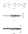
- FIG. 4 a shows cross sections of the shaft of the pop-pin in FIG. 1 according to various embodiments.
- FIG. 4 b depicts a pop-pin of FIG. 1 with a t-shaped handle.
- FIG. 4 c depicts a pop-pin of FIG. 1 with a disc-shaped handle.
- FIGS. 5 a - 5 d depicts a weight stack in a conventional weight-training machine as used with the pop-pin of FIG. 1 .
- FIG. 6 is a flowchart of a method of using the pop-pin of FIG. 1 .
- the present invention is directed towards a weight selecting pop-pin device and methods to use the same in a pin selected weight-training device.
- FIG. 1 shows an assembled pop-pin 530 according to various embodiments of the present invention.
- FIG. 1 shows the pop-pin can include a shaft 100 that includes first end 102 and a second end 108 .
- shaft 100 can include a first shaft 103 and a second shaft 110 attached to one another.
- First shaft 103 can include first end 102 and second shaft 110 can include second end 108 .
- first shaft 103 can include a third end 104 that abuts a fourth end 105 of second shaft 110 when first shaft 103 and second shaft 110 are connected to form shaft 100 .
- the junction of third end 104 and fourth end 105 can define a joint having a shoulder 106 .
- third end 104 and fourth end 105 can define a joint or connection having a shoulder 106 .
- Shoulder 106 can have a dimension defined by the difference between the diameters of the first shaft 103 and second shaft 110 .
- the dimension of shoulder 106 is the difference between diameters 103 D and 110 D, where diameter 103 D is the diameter of first shaft 103 and diameter 110 D is the diameter of second shaft 110 .
- a spring 120 can be dimensioned to fit around the second shaft 110 and be captured by shoulder 106 and handle 150 .
- washer 140 can be used to compress spring 120 against handle 150 until washer 140 engages trigger catch point 130 .
- Trigger catch point 130 can be dimensioned and shaped to hold washer 140 in an unstable equilibrium position between trigger catch point 130 and compressed spring 120 .
- the unstable equilibrium can be disturbed by applying a shock or other vibration to the pop-pin 530 .
- washer 140 can be released from catch point 130 and biased against the end of shoulder 106 or some other object into which the pop-pin 530 can be inserted.
- the pop-pin 530 can be set to the unstable equilibrium point at catch point 130 and inserted into the channel 560 of a weight plate 60 and a corresponding channel 515 A in a vertical guide bar 510 of a weight-training machine shown in FIGS. 5 a and 5 b .
- Use of the pop-pin 530 will be discussed in more detail below.
- the first shaft 103 can be any shape or size compatible with a desired weight plate or weight-plate stack. For example, most weight-training machines have round holes with cylindrical channels in the weight plates and the vertical bar. In such cases, it would be beneficial for the first shaft 103 to be an appropriately sized cylinder so that first end 102 of the first shaft 103 can be easily inserted into the channels of the weight plates and the vertical bar. In other embodiments, the diameter of the first shaft 103 can be smaller than the diameter of the channel in the weight plates and the vertical bar to allow for a loose fit. In some embodiments, the diameter 103 D of the first cylindrical shaft can be approximately 9 mm.
- the first shaft 103 and the second shaft 110 can be solid or hollow.
- the first shaft 103 and second shaft 110 can be of any shape of solid or hollow prisms compatible with the channels in the weight plates and the vertical bar with which pop-pin 530 is intended to be used.
- the first shaft 103 and second shaft 110 can be rectangular, oval, triangular or any other shape prism. Examples of possible cross-sectional shaft shapes are shown in FIG. 4 a .
- the shafts of pop-pin 530 can have triangular cross-section 410 , oval cross-section 420 , hexagonal cross-section 430 , rectangular 440 , octagonal cross-section 450 , pentagonal cross-section 560 or any other suitable cross-section.
- the first shaft 103 and second shaft 110 can be made of any material suitable for supporting the weight in a stack of weight plates in a weight-training machine.
- the first shaft 103 and the second shaft 110 can be metal, ceramic, fiber reinforced plastics or resins or any other appropriate material suitable for weight-bearing needs of the shaft.
- First shaft 103 and second shaft 110 can comprise any number of materials.
- Spring 120 can be a compression spring with a sufficient spring stiffness coefficient, k, sufficient to exert some force, F ⁇ , when compressed from its retention position, or retention catch point, adjacent to third end 104 of first shaft 103 to the unstable equilibrium position at trigger catch point 130 .
- Spring 120 can be any suitable compression spring including, but not limited to, a coil compression spring or compressible rubber or polymer material with a similar stiffness spring constant or resistive compression characteristic.
- Trigger catch point 130 can be any suitable extension extending from the shaft 100 , first shaft 103 or second shaft 110 .
- trigger catch point 130 can be a screw.
- the screw can be threaded into an appropriately threaded hole so that it extends from the exterior surface of shaft 100 .
- trigger catch point 130 can be a peg soldered or welded onto or into the second shaft 100 .
- trigger catch point 130 may be machined from the same piece of material from which shaft 100 , first shaft 103 or second shaft 110 are formed.
- Washer 140 can be a standard washer configured with a central channel, extending from an aperture on a first side of the washer 140 to an aperture on a second side of the washer, of sufficient size to allow for washer 140 to move along shaft 100 or second shaft 110 , yet be able to be set into an unstable equilibrium position at trigger catch point 130 .
- Washer 140 can be made from metal, plastic, resin, fiber reinforced plastic or resin or any other material suitable for sliding along shaft 100 or second shaft 110 and catching on trigger catch point 130 and having sufficient strength when held against spring 120 and catch point 130 without breaking, bending, cracking or otherwise failing.
- Washer 140 can be a standardized or off-the-shelf washer. Use of an off-the-shelf washer can help increase the cost effectiveness of manufacturing the pop-pin.
- Handle 150 can be attached to second shaft 110 at second end 108 and can be any suitable shape conducive to being easily handled manually and capturing retaining spring 120 .
- the size shape and material of the handle 150 can be modified to suit the particular design aesthetic or look desired for the pop-pin.
- handle 150 can be a sphere, spheroid, a T-handle, or a disk or other flat handle.
- FIGS. 4 b and 4 c show variations of handle 150 according to various embodiments of the present invention. For example, FIG. 4 b shows the pop-pin with a T-handle 155 and FIG. 4 c shows the pop-pin with a disk handle 160 .
- FIG. 2 a depicts the pop-pin of FIG. 1 with spring 120 biased against handle 150 by pressing washer 140 until it is engaged with trigger catch point 130 .
- the configuration of the pop-pin depicted in FIG. 2 a represents an unstable equilibrium position in which washer 140 can be easily dislodged from trigger catch point 130 by a sufficient shock to the pop-pin.
- the shock to the pop-pin can be provided by lifting up a vertical bar in which the pop-pin 530 has been inserted to engage one or more weight plates on a weight-training machine
- FIG. 2 b depicts another variation of the pop-pin in which washer 140 is removed and the end of spring 120 is used to engage the trigger catch point 130 .
- Such embodiments can further reduce the cost of manufacturing and assembling the pop-pin 530 by reducing the number of parts. Furthermore, depending on the relative difference in diameter between the second shaft 110 and spring 120 , the height of trigger catch point 130 relative to the exterior surface of shaft 110 can be extended or reduced to compensate for the lack of washer 140 .
- FIGS. 3 a to 3 c show various exploded views of pop-pins according to various embodiments of the present invention.
- first shaft 103 which can have first end 102 and third end 104
- second shaft 110 which can have second end 105 and fourth end 108
- external threads 115 can be on third end 104 on first shaft 103 and the corresponding internal threads 116 can be in second end 105 of second shaft 110 .
- the shafts can also be connected by other types of engagement such as friction fit, snap fit, welded junction, etc.
- Handle 150 and second shaft 110 with threads 115 can be formed of the same piece of material.
- the handle 150 , second shaft 110 with threads 115 can be milled, cast or injection molded.
- FIG. 3 b illustrates an unassembled pop-pin in which the first shaft 103 , second shaft 110 with threads 115 and handle 150 are all separately manufactured parts.
- second shaft 110 can be inserted or otherwise fixed to handle 150 .
- second shaft 110 can be glued, friction fit or threaded into handle 150 .
- handle 150 can be drilled and threaded to accept a setscrew or rivet to engage with the second shaft 110 once it is inserted into the handle 150 .
- FIG. 3 c shows pop-pin 530 in which the pop-pin includes a single shaft 100 instead of the first shaft 103 and second shaft 110 .
- a retention catch point 135 is added so as to capture spring 120 between retention catch point 135 and handle 150 .
- Retention catch point 135 can be dimensioned so that spring 120 cannot escape shaft 100 .
- Such embodiments can further reduce the cost and complexity of manufacturing and assembling the pop-pin by reducing the bill of materials required for a single pop-pin.
- FIGS. 5 a to 5 d illustrate how pop-pin 530 is used in conjunction with a pin 520 and a weight-training machine having a weight plate stack 500 and a vertical bar 510 .
- FIG. 5 a depicts a stack of weight plates 500 found in many typical weight-training machines.
- stack of weight plates 500 includes a plurality of weight plates each having a hole in the front face with an interior channel, such as channel 517 , that extends either partially or completely through each weight plate.
- vertical guide bar 510 can also have a plurality of channels 515 configured to run perpendicularly to the surface of the vertical guide bar 510 and extend either partially or entirely through the vertical guide bar 510 .
- Each channel in each weight plate in stack 500 can be configured to accept a pin used to select the amount of weight to be lifted by vertical bar 510 .
- channels 515 in vertical guide bar 510 can align with the channels 517 in the weight plates in the stack 500 so that pin 520 or 530 can be readily inserted into a channel of a weight plate in stack 500 and engage a channel 515 in vertical guide bar 510 .
- FIG. 5 b illustrates pop-pin 530 inserted into weight plate 60 and pin 520 inserted into weight plate 30 .
- the spring 120 and possibly washer 140 of pop-pin 130 can be manually compressed and arranged to catch on trigger catch point 130 in an unstable equilibrium position.
- pop-pin 530 can be referred to as being “loaded” or “cocked.”
- stacks 504 in 505 are ready to be lifted.
- bar 510 when bar 510 is raised all weight plates above weight plate 60 , i.e. stacks 504 and 505 , in stack 500 are also raised.
- vertical guide bar 510 can be raised and lowered by a system of pulleys and cables by a user performing a bench press exercise.
- the action of engaging weight plates 60 with vertical guide bar 510 via pop-pin 530 can disturb the pop-pin 530 such that spring 120 is knocked out of its unstable equilibrium position at trigger catch point 130 .
- spring 120 is biased against the handle 150 and the front surface of plate 60 .
- pop-pin 530 would be ejected from the channels 515 and 517 by the force exerted on handle 150 by spring 120 biased against the front of weight plate 60 .
- the shock to the pop-pin of engaging and lifting the stacks 505 and 504 of weight plates disturbs the unstable equilibrium and causes washer 140 to overcome the trigger catch point 130 and be biased against the exterior surface of the particular weight plate into which the pop-pin is inserted.
- the force of the stack of weight plates pressing down on the pop-pin causes the pop-pin to press against the interior surface of the channels 517 and 515 in the weight plate and vertical guide bar into which the pop-pin is inserted.
- the static friction between the pop-pin 530 and the interior of the channels 517 and 515 A is sufficient to overcome the force of the spring 120 biased against washer 140 and the exterior surface of the weight plate 60 into which the pop-pin is inserted and handle 150 to hold the pop-pin 530 in place while a user performs an exercise using the weight-training machine.
- the k coefficient of the spring can be chosen such that the least amount of weight selectable with the pop-pin can create sufficient friction to prevent the pop-pin from ejecting from the channels as long as some number of the plates in weight-stack 500 is engaged with the vertical guide bar 510 via the pop-pin 530 .
- vertical guide bar 510 can be lowered to a resting position such that pop-pin 530 is no longer bearing the weight of stacks 504 and 505 and the static friction between pop-pin 530 and the channels 517 of weight plates 60 and 515 A of vertical guide bar 510 is reduced to the point that the force exerted by compressed spring 120 on handle 150 is enough to eject pop-pin 530 from the channels 517 and 515 A.
- the user may only have to tap lightly stacks 504 and 505 against the top surface of weight plate 70 to achieve a brief moment in a resting position for pop-pin 530 to be ejected.
- a user can decide to reduce the number of weight plates he or she is lifting while in the midst of performing an exercise. For example, a user performing a bench press may wish to perform 10 repetitions with the weight stack set to lift weight plates 60 and the weight plates above it in stack 500 , i.e. stacks 504 in 505 , and then perform 10 repetitions with the weight stack set to lift only stack 504 .
- a user can simply return the weight stack comprising stacks 504 in 505 to a resting position, at which point pop-pin 530 will automatically be ejected, as shown in FIG. 5 c , and the user can continue the second set of 10 repetitions using only stack 504 , as shown in FIG. 5 d , without interruption or the need to manually change the position of a weight selecting pin.
- FIG. 6 is a flowchart of a method 600 for using pop-pin 530 with a weight-training machine that can include a stack of weight plates disposed around a vertical bar used to lift one or more of the weight plates.
- the user can manually compress spring 120 to engage the end of spring 120 or washer 140 with trigger catch point 130 to position spring 120 into an unstable equilibrium.
- This step can be completed manually, however this step can also be accomplished with the use of a customized spring loading mechanism whereby a user can insert the pop-pin into a channel using his or her body weight or mechanical lever to set spring 120 into an unstable equilibrium position.
- the user can insert the loaded pop-pin 530 into the a stack of weight plates and a vertical guide bar so as to engage the stack of weight plates at a point lower in the stack than another conventional pin inserted into the weight stack.
- This step creates a combined stack of two stacks with the combined stack including all the weight plates above the loaded pop-pin which includes a second lighter stack including all the weight plates above the weight plate into which the conventional pin is inserted.
- the shock to the spring causes the spring and/or the washer to be disturbed from the unstable equilibrium position on the trigger catch point.
- the spring is then biased against the weight plate in step 630 .
- the initial jerk of the vertical guide bar can be sufficient to shock the loaded spring on the pop-pin out of its unstable equilibrium point.
- the user can then lift and lower the vertical guide bar and the combined stack of weight plates making sure not to return the stack to a resting position so at to keep the pop-pin engaged with the stack of weight plates at step 640 .
- the user When the user is ready to reduce the weight of the stack of weight plates to that of only the weight plates engaged by the conventional pin, the user need only return the combined stack of weights to a resting position in step 650 .
- the friction between the pop-pin and the interior of the channels in the weight plate and the vertical guide bar into which the pop-pin is inserted is reduced to the point that the force exerted by the spring can overcome the friction so as to eject the pop-pin from the weight stack.
- the vertical guide bar can engage only the weight plates in the stack above the weight plate into which the conventional pin is inserted. At this point, the user can immediately continue lifting and lowering the lighter stack of weight plates supported by the conventional pin at step 660 .
- the present invention may be embodied in other specific forms without departing from the essential characteristics thereof.
- the pop-pin may include any combination of shaft sizes, shapes or handle configurations suitable for insertion into and supporting the weight of a weight stack.
- Many other embodiments are possible without deviating from the spirit and scope of the invention. These other embodiments are intended to be included within the scope of the present invention, which is set forth in the following claims.
Landscapes
- Health & Medical Sciences (AREA)
- Life Sciences & Earth Sciences (AREA)
- Biophysics (AREA)
- Orthopedic Medicine & Surgery (AREA)
- General Health & Medical Sciences (AREA)
- Physical Education & Sports Medicine (AREA)
- Rehabilitation Tools (AREA)
- Percussion Or Vibration Massage (AREA)
Abstract
A pop-pin and a method for using the pop-pin with a weight-training machine to perform mixed-weight sets of exercise are disclosed. A pop-pin having a spring loaded into an unstable equilibrium position can be inserted into a weight stack to select a weight and vertical guide bar while another conventional pin is inserted into the same weight stack and the vertical guide bar at a position above the pop-pin. A user can then operate the weight-training machine, at which point the spring on the pop-pin is dislodged from the unstable equilibrium position and presses on the weight plate into which it is inserted. When the weight stack is lowered, thus reducing the load of weight on the pop-pin, the force of the spring pressing against the weight plate ejects the pop-pin from the weight plate. At this point, the user can continue the exercise with the smaller stack.
Description
The present invention is directed towards a device and related methods for use with various styles of weight-training machines. Weight-training machines have enjoyed increased popularity with users over the years for a number of reasons. In addition to providing a convenient and safe method of changing resistance, weight-training machines also provide a structured, relatively safe and informative approach to weight training for individuals seeking a self-guided workout.
A conventional weight-training machine uses gravity as the primary source of resistance, and a combination of so-called “simple machines” to convey that resistance to the person using the machine. Each of the machines (pullies, levers, wheels, inclines) changes the mechanical advantage of the overall machine relative to the weight and allows a user to take advantage of the gravitational resistance while performing exercises in many directions.
Most styles of weight machines have a set of massive weight plates configured with a least one hole through each of the plates. Each plate is disposed in a stack with at least one vertical guide bar disposed through the holes. The vertical guide bar is configured to be raised and lowered via a combination of simple machines configured to translate the motion of an exercise into an up and down motion. By selectively attaching a number of plates to the vertical guide bar, the resistance of the exercise can be changed according to the preference of the user.
To provide for quick and easy changes in the number of weights attached to the vertical guide bar, both the vertical guide bar and the plates have holes drilled into them to accept a pin. A pin is inserted into the hole in a plate and a corresponding hole in the vertical guide bar. When the vertical guide bar is lifted, the plate into which the pin is inserted, and all the plates located above it in the stack, rest on the pin and are thus also lifted. The plates below the pin do not rise. This allows the same machine to provide several levels of resistance over the same range of motion with an adjustment that requires very little effort to accomplish in itself.
The means of lifting the bar vary. Some machines have a roller at the top of the bar that sits on a lever. When the lever is raised, the bar can go up and the roller moves along the lever, allowing the bar to stay vertical. On some machines, the bar is attached to a hinge on the lever, which causes swaying in the bar and the plates as the lever goes up and down. On other machines, the bar is attached to a cable or belt, which runs through pulleys or over a wheel. The other end of the cable will either be a handle, bar or strap that the user holds or wraps around some body part, or will be attached to a lever, adding further simple machines to the mechanical chain.
Usually, each plate is marked with a number. On some machines, these numbers give the actual weight of the plate and those above it and on others machines, the number gives the force at the user's actuation point with the machine. Finally, on some machines the number is simply an index counting the number of plates being lifted.
There are numerous types of training machines that are designed to assist users in performing various types of weight-training exercises. For example, there are benchpress machines, bicep curl machines, leg press machines, etc. Additionally, there are various techniques and methodologies for using each of the various weight-training machines. For instance, many users tend to do multiple “sets” of some number of repetitions or “reps.” For example, a user may perform 3 sets of 10 repetitions of a benchpress exercise using a particular weight as part of his or her workout. This can be achieved by inserting the pin into the plate indicating the desired amount of weight. However, some users prefer to do sets of repetitions where each set includes a number of repetitions at a first heavier weight and then a second number of repetitions at a second weight. This is sometimes referred to as “mixed-weight set training” or “reverse pyramid training.”
To perform a set of an exercise with two different weight settings, or a mixed-weight set, on a conventional weight-training machine requires the user to stop during his or her set to change the location of the pin in the weight stack. Stopping not only requires more time to complete the exercise, it also lessens the effectiveness of the mixed-weight set exercise. To solve this problem, some manufacturers of weight-training machines have devised complicated and expensive devices to change the weight stack at some point during a set.
One method of changing the weight stack involves setting two or more pins in the weight stack and setting a timer that controls a mechanical device that can eject the lower of the two pins to release a lower portion of the stack of weights to reduce the weight lifted. This method of course requires not only a timer, but also the mechanism to remove the pin when the timer goes off. Such mechanisms are costly and must either be fitted to the weight-training machine at the time of manufacture or included in a complicated retrofit system. Additionally, the timer aspect forces the user to complete the first phase of a mixed-weight set in predetermined amount of time, often causing the weight to be lowered sooner or later than the user would like. Such solutions for performing mixed weight exercises on a weight-training machine are not feasible for weight-training machines that are already deployed at fitness clubs or in home gyms.
As such, there is a need for a simple, easily-adaptable and inexpensive device to allow users and/or owners of existing weight-training machines quick performance of mixed-weight weight-training exercises.
Embodiments of the present invention are directed to a pop-pin, having a shaft with an exterior surface, a first end and a second end. The pop-pin can also include a trigger catch extending perpendicularly to the exterior surface of the shaft, a retention catch extending perpendicularly to the exterior surface of the shaft and disposed between the trigger catch and the first end of the shaft. A handle can be disposed onto the second end of the shaft and a coil compression spring can be disposed around the shaft and dimensioned for capture between the handle and the retention catch. The trigger catch extends sufficiently from the exterior surface of the shaft to maintain the spring in an unstable equilibrium position when the coil compression spring is biased against the handle. The retention catch extends sufficiently from the exterior surface of the shaft to retain the coil compression spring between the handle and the retention catch.
The present invention is directed towards a weight selecting pop-pin device and methods to use the same in a pin selected weight-training device.
Weight Selecting Pop-pins
When connected, the interface of third end 104 and fourth end 105 can define a joint or connection having a shoulder 106. Shoulder 106 can have a dimension defined by the difference between the diameters of the first shaft 103 and second shaft 110. In FIG. 1 , the dimension of shoulder 106 is the difference between diameters 103D and 110D, where diameter 103D is the diameter of first shaft 103 and diameter 110D is the diameter of second shaft 110.
A spring 120 can be dimensioned to fit around the second shaft 110 and be captured by shoulder 106 and handle 150. In use, washer 140 can be used to compress spring 120 against handle 150 until washer 140 engages trigger catch point 130. Trigger catch point 130 can be dimensioned and shaped to hold washer 140 in an unstable equilibrium position between trigger catch point 130 and compressed spring 120.
The unstable equilibrium can be disturbed by applying a shock or other vibration to the pop-pin 530. When the unstable equilibrium is disturbed, washer 140 can be released from catch point 130 and biased against the end of shoulder 106 or some other object into which the pop-pin 530 can be inserted. For example, the pop-pin 530 can be set to the unstable equilibrium point at catch point 130 and inserted into the channel 560 of a weight plate 60 and a corresponding channel 515A in a vertical guide bar 510 of a weight-training machine shown in FIGS. 5 a and 5 b. Use of the pop-pin 530 will be discussed in more detail below.
The first shaft 103 can be any shape or size compatible with a desired weight plate or weight-plate stack. For example, most weight-training machines have round holes with cylindrical channels in the weight plates and the vertical bar. In such cases, it would be beneficial for the first shaft 103 to be an appropriately sized cylinder so that first end 102 of the first shaft 103 can be easily inserted into the channels of the weight plates and the vertical bar. In other embodiments, the diameter of the first shaft 103 can be smaller than the diameter of the channel in the weight plates and the vertical bar to allow for a loose fit. In some embodiments, the diameter 103D of the first cylindrical shaft can be approximately 9 mm. The first shaft 103 and the second shaft 110 can be solid or hollow. In other embodiments, the first shaft 103 and second shaft 110 can be of any shape of solid or hollow prisms compatible with the channels in the weight plates and the vertical bar with which pop-pin 530 is intended to be used. For example, the first shaft 103 and second shaft 110 can be rectangular, oval, triangular or any other shape prism. Examples of possible cross-sectional shaft shapes are shown in FIG. 4 a. As shown, the shafts of pop-pin 530 can have triangular cross-section 410, oval cross-section 420, hexagonal cross-section 430, rectangular 440, octagonal cross-section 450, pentagonal cross-section 560 or any other suitable cross-section.
The first shaft 103 and second shaft 110 can be made of any material suitable for supporting the weight in a stack of weight plates in a weight-training machine. For example the first shaft 103 and the second shaft 110 can be metal, ceramic, fiber reinforced plastics or resins or any other appropriate material suitable for weight-bearing needs of the shaft. First shaft 103 and second shaft 110 can comprise any number of materials.
Handle 150 can be attached to second shaft 110 at second end 108 and can be any suitable shape conducive to being easily handled manually and capturing retaining spring 120. The size shape and material of the handle 150 can be modified to suit the particular design aesthetic or look desired for the pop-pin. For example, handle 150 can be a sphere, spheroid, a T-handle, or a disk or other flat handle. FIGS. 4 b and 4 c show variations of handle 150 according to various embodiments of the present invention. For example, FIG. 4 b shows the pop-pin with a T-handle 155 and FIG. 4 c shows the pop-pin with a disk handle 160.
Handle 150 and second shaft 110 with threads 115 can be formed of the same piece of material. In such embodiments, the handle 150, second shaft 110 with threads 115 can be milled, cast or injection molded. FIG. 3 b illustrates an unassembled pop-pin in which the first shaft 103, second shaft 110 with threads 115 and handle 150 are all separately manufactured parts. In such embodiments second shaft 110 can be inserted or otherwise fixed to handle 150. To fix the second shaft 110 to handle 150, second shaft 110 can be glued, friction fit or threaded into handle 150. In other embodiments handle 150 can be drilled and threaded to accept a setscrew or rivet to engage with the second shaft 110 once it is inserted into the handle 150.
With loaded pop-pin 530 inserted into the channel 517 of weight plate 60 and the corresponding channel 515 of vertical guide bar 510, stacks 504 in 505 are ready to be lifted. As such, when bar 510 is raised all weight plates above weight plate 60, i.e. stacks 504 and 505, in stack 500 are also raised. For example, vertical guide bar 510 can be raised and lowered by a system of pulleys and cables by a user performing a bench press exercise. The action of engaging weight plates 60 with vertical guide bar 510 via pop-pin 530 can disturb the pop-pin 530 such that spring 120 is knocked out of its unstable equilibrium position at trigger catch point 130. Thus released, spring 120 is biased against the handle 150 and the front surface of plate 60. In the absence of any intervening force or latch, pop-pin 530 would be ejected from the channels 515 and 517 by the force exerted on handle 150 by spring 120 biased against the front of weight plate 60.
In embodiments of the present invention, the shock to the pop-pin of engaging and lifting the stacks 505 and 504 of weight plates disturbs the unstable equilibrium and causes washer 140 to overcome the trigger catch point 130 and be biased against the exterior surface of the particular weight plate into which the pop-pin is inserted. The force of the stack of weight plates pressing down on the pop-pin causes the pop-pin to press against the interior surface of the channels 517 and 515 in the weight plate and vertical guide bar into which the pop-pin is inserted. As shown in the cross-sectional view in FIG. 5 b, the static friction between the pop-pin 530 and the interior of the channels 517 and 515A is sufficient to overcome the force of the spring 120 biased against washer 140 and the exterior surface of the weight plate 60 into which the pop-pin is inserted and handle 150 to hold the pop-pin 530 in place while a user performs an exercise using the weight-training machine. The k coefficient of the spring can be chosen such that the least amount of weight selectable with the pop-pin can create sufficient friction to prevent the pop-pin from ejecting from the channels as long as some number of the plates in weight-stack 500 is engaged with the vertical guide bar 510 via the pop-pin 530.
After some number of repetitions of raising and lowering stacks 504 and 505, vertical guide bar 510 can be lowered to a resting position such that pop-pin 530 is no longer bearing the weight of stacks 504 and 505 and the static friction between pop-pin 530 and the channels 517 of weight plates 60 and 515A of vertical guide bar 510 is reduced to the point that the force exerted by compressed spring 120 on handle 150 is enough to eject pop-pin 530 from the channels 517 and 515A. In some embodiments, the user may only have to tap lightly stacks 504 and 505 against the top surface of weight plate 70 to achieve a brief moment in a resting position for pop-pin 530 to be ejected. Since all it takes is for stacks 504 of 505 to touch the top surface of weight plates 70 to eject pop-pin 530, a user can decide to reduce the number of weight plates he or she is lifting while in the midst of performing an exercise. For example, a user performing a bench press may wish to perform 10 repetitions with the weight stack set to lift weight plates 60 and the weight plates above it in stack 500, i.e. stacks 504 in 505, and then perform 10 repetitions with the weight stack set to lift only stack 504. To reduce the weight of combined stacks 505 and 504 to only the weight of stack 504, a user can simply return the weight stack comprising stacks 504 in 505 to a resting position, at which point pop-pin 530 will automatically be ejected, as shown in FIG. 5 c, and the user can continue the second set of 10 repetitions using only stack 504, as shown in FIG. 5 d, without interruption or the need to manually change the position of a weight selecting pin.
At step 620 the user can insert the loaded pop-pin 530 into the a stack of weight plates and a vertical guide bar so as to engage the stack of weight plates at a point lower in the stack than another conventional pin inserted into the weight stack. This step creates a combined stack of two stacks with the combined stack including all the weight plates above the loaded pop-pin which includes a second lighter stack including all the weight plates above the weight plate into which the conventional pin is inserted.
When the user lifts the stack of weight plates so as to engage the pop-pin with the stack of weight plates, the shock to the spring causes the spring and/or the washer to be disturbed from the unstable equilibrium position on the trigger catch point. The spring is then biased against the weight plate in step 630. The initial jerk of the vertical guide bar can be sufficient to shock the loaded spring on the pop-pin out of its unstable equilibrium point. The user can then lift and lower the vertical guide bar and the combined stack of weight plates making sure not to return the stack to a resting position so at to keep the pop-pin engaged with the stack of weight plates at step 640. When the user is ready to reduce the weight of the stack of weight plates to that of only the weight plates engaged by the conventional pin, the user need only return the combined stack of weights to a resting position in step 650. By resting the weight stack located above the pop-pin on the weight stack below the pop-pin, the friction between the pop-pin and the interior of the channels in the weight plate and the vertical guide bar into which the pop-pin is inserted is reduced to the point that the force exerted by the spring can overcome the friction so as to eject the pop-pin from the weight stack.
Once the pop-pin has been ejected from the stack, the vertical guide bar can engage only the weight plates in the stack above the weight plate into which the conventional pin is inserted. At this point, the user can immediately continue lifting and lowering the lighter stack of weight plates supported by the conventional pin at step 660.
One or more features from any embodiment may be combined with one or more features of any other embodiment without departing from the scope of the invention.
A recitation of “a”, “an” or “the” is intended to mean “one or more” unless specifically indicated to the contrary.
As will be understood by those skilled in the art, the present invention may be embodied in other specific forms without departing from the essential characteristics thereof. For example, the pop-pin may include any combination of shaft sizes, shapes or handle configurations suitable for insertion into and supporting the weight of a weight stack. Many other embodiments are possible without deviating from the spirit and scope of the invention. These other embodiments are intended to be included within the scope of the present invention, which is set forth in the following claims.
Claims (8)
1. A pop-pin, comprising: a shaft comprising an exterior surface; a first end; a second end; and a first cylinder having a first diameter; a second cylinder having a second diameter smaller than the first diameter of the first cylinder and comprising the second end and a third end; wherein the first cylinder comprises the first end and a fourth end; and wherein the third end of the second cylinder is attached to the fourth end of the first cylinder; and wherein the fourth end of the first cylinder comprises internal screw threads, and wherein the third end of the second cylinder comprises external screw threads and the first cylinder and the second cylinder are configured for threaded engagement; a trigger catch extending perpendicularly to the exterior surface of the shaft; a retention catch extending perpendicularly to the exterior surface of the shaft and disposed between the trigger catch and the first end of the shaft; a handle disposed on the second end of the shaft; and a coil compression spring disposed around the shaft and dimensioned for capture between the handle and the retention catch; wherein the trigger catch extends sufficiently from the exterior surface of the shaft to maintain the spring in an unstable equilibrium position when the coil compression spring is biased against the handle, and wherein the retention catch extends sufficiently from the exterior surface of the shaft to retain the coil compression spring between the handle and the retention catch.
2. The pop-pin of claim 1 wherein the fourth end of the first cylinder comprises external screw threads, and wherein the third end of the second cylinder comprises internal screw threads and the first cylinder and the second cylinder are configured for threaded engagement.
3. The pop-pin of claim 1 wherein the fourth end of the first cylinder comprises the retention catch.
4. The pop-pin of claim 3 wherein the retention catch comprises a shoulder formed by the coupling of the first and second cylinders and defined by the difference in diameters of the first and second cylinders.
5. The pop-pin of claim 3 wherein the handle is a spheroid.
6. The pop-pin of claim 5 further comprising a washer comprising: a first surface having a first hole; a second surface having a second hole; and a channel from the first hole to the second hole; wherein the second cylinder is disposed through the channel such that the first end of the first cylinder and the coil compression spring capture the washer.
7. The pop-pin of claim 3 wherein the handle comprises a T-bar.
8. The pop-pin of claim 3 wherein the handle comprises a planar element.
Priority Applications (1)
| Application Number | Priority Date | Filing Date | Title |
|---|---|---|---|
| US12/582,568 US8454260B2 (en) | 2009-10-20 | 2009-10-20 | Weight selecting pop-pin |
Applications Claiming Priority (1)
| Application Number | Priority Date | Filing Date | Title |
|---|---|---|---|
| US12/582,568 US8454260B2 (en) | 2009-10-20 | 2009-10-20 | Weight selecting pop-pin |
Publications (2)
| Publication Number | Publication Date |
|---|---|
| US20110091272A1 US20110091272A1 (en) | 2011-04-21 |
| US8454260B2 true US8454260B2 (en) | 2013-06-04 |
Family
ID=43879412
Family Applications (1)
| Application Number | Title | Priority Date | Filing Date |
|---|---|---|---|
| US12/582,568 Expired - Fee Related US8454260B2 (en) | 2009-10-20 | 2009-10-20 | Weight selecting pop-pin |
Country Status (1)
| Country | Link |
|---|---|
| US (1) | US8454260B2 (en) |
Cited By (9)
| Publication number | Priority date | Publication date | Assignee | Title |
|---|---|---|---|---|
| US20150133274A1 (en) * | 2011-11-18 | 2015-05-14 | Dominic A. Simonetti | Weight Lifting and Selector Pin Assembly |
| USD740897S1 (en) | 2014-04-03 | 2015-10-13 | Heinz Richard Miltner | Spring loaded weight stack selector pin |
| US9242134B2 (en) | 2013-03-15 | 2016-01-26 | Heinz Richard Miltner | Spring loaded weight stack selector pin |
| US20160059062A1 (en) * | 2011-11-18 | 2016-03-03 | Dominic A. Simonetti | Weight Lifting and Selector Pin Assembly |
| US9468791B2 (en) * | 2013-02-14 | 2016-10-18 | Steven Lojek | Selectorized weight stack ejecting pin |
| US9827160B2 (en) | 2014-11-26 | 2017-11-28 | Cheng I Chou | Safety key that identifies improper insertion |
| US9950205B2 (en) | 2016-03-14 | 2018-04-24 | Bronze Fist Design, Inc. | Weight lifting and selector pin assembly |
| US10066759B1 (en) * | 2016-04-04 | 2018-09-04 | Bnsf Railway Company | Locking / indexing pin |
| US12070643B1 (en) * | 2023-08-09 | 2024-08-27 | Stack Bands, LLC | Supplemental resistance device for selectorized weight training machines |
Families Citing this family (9)
| Publication number | Priority date | Publication date | Assignee | Title |
|---|---|---|---|---|
| WO2013126580A1 (en) * | 2012-02-21 | 2013-08-29 | Whiterock Exercise, Inc. | Linear bearings and alignment method for weight lifting apparatus |
| CN103470597B (en) * | 2013-09-30 | 2015-04-29 | 浙江师范大学 | Locking positioning device |
| CN103470598B (en) * | 2013-09-30 | 2016-01-27 | 浙江师范大学 | A kind of lock in place device with T-shaped lock pin |
| CN103470596B (en) * | 2013-09-30 | 2015-07-15 | 福建九鼎建设集团有限公司 | Locking positioning device |
| ES2715644A1 (en) * | 2017-12-05 | 2019-06-05 | Univ Catalunya Politecnica | MACHINE TO EXERCISE BICEPS AND TRICEPS |
| USD893642S1 (en) * | 2018-03-08 | 2020-08-18 | Coulter Ventures, Llc. | Resistance band peg |
| USD884097S1 (en) * | 2018-06-29 | 2020-05-12 | Coulter Ventures, Llc. | Weight storage pin |
| US20220152442A1 (en) * | 2020-11-18 | 2022-05-19 | Shawn DONALDSON | Weight assist device |
| USD1029151S1 (en) * | 2023-10-16 | 2024-05-28 | Yongkang Yulai Industry and Trade Co., Ltd. | Weight stack pin |
Citations (5)
| Publication number | Priority date | Publication date | Assignee | Title |
|---|---|---|---|---|
| US5306221A (en) * | 1992-12-15 | 1994-04-26 | Abe Itaru | Weight adjusting device for muscle training machine |
| US5556362A (en) * | 1995-03-20 | 1996-09-17 | Whipps; Allen M. | Automatic weight stack pin selector |
| US7473211B2 (en) * | 2002-01-28 | 2009-01-06 | Lee Byung-Don | Device for controlling weight of a weight training machine and its method |
| US7485076B2 (en) * | 2003-12-15 | 2009-02-03 | Byung Don Lee | Weight-training machine having independent power generating function and stack for the machine |
| US7507189B2 (en) * | 2004-12-14 | 2009-03-24 | Nautilus, Inc. | Exercise weight stack apparatus |
-
2009
- 2009-10-20 US US12/582,568 patent/US8454260B2/en not_active Expired - Fee Related
Patent Citations (6)
| Publication number | Priority date | Publication date | Assignee | Title |
|---|---|---|---|---|
| US5306221A (en) * | 1992-12-15 | 1994-04-26 | Abe Itaru | Weight adjusting device for muscle training machine |
| US5556362A (en) * | 1995-03-20 | 1996-09-17 | Whipps; Allen M. | Automatic weight stack pin selector |
| US7473211B2 (en) * | 2002-01-28 | 2009-01-06 | Lee Byung-Don | Device for controlling weight of a weight training machine and its method |
| US7485076B2 (en) * | 2003-12-15 | 2009-02-03 | Byung Don Lee | Weight-training machine having independent power generating function and stack for the machine |
| US7507189B2 (en) * | 2004-12-14 | 2009-03-24 | Nautilus, Inc. | Exercise weight stack apparatus |
| US7540832B2 (en) * | 2004-12-14 | 2009-06-02 | Nautilus, Inc. | Exercise weight stack methods and apparatus |
Cited By (13)
| Publication number | Priority date | Publication date | Assignee | Title |
|---|---|---|---|---|
| US9468792B2 (en) * | 2011-11-18 | 2016-10-18 | Bronze Fist Design, Inc. | Weight lifting and selector pin assembly |
| US10350446B2 (en) | 2011-11-18 | 2019-07-16 | Bronze Fist Design, Inc. | Weight lifting and selector pin assembly |
| US20150133274A1 (en) * | 2011-11-18 | 2015-05-14 | Dominic A. Simonetti | Weight Lifting and Selector Pin Assembly |
| US20160059062A1 (en) * | 2011-11-18 | 2016-03-03 | Dominic A. Simonetti | Weight Lifting and Selector Pin Assembly |
| US9463345B2 (en) * | 2011-11-18 | 2016-10-11 | Bronze Fist Design, Inc. | Weight lifting and selector pin assembly |
| US9468791B2 (en) * | 2013-02-14 | 2016-10-18 | Steven Lojek | Selectorized weight stack ejecting pin |
| US9242134B2 (en) | 2013-03-15 | 2016-01-26 | Heinz Richard Miltner | Spring loaded weight stack selector pin |
| USD740897S1 (en) | 2014-04-03 | 2015-10-13 | Heinz Richard Miltner | Spring loaded weight stack selector pin |
| US9827160B2 (en) | 2014-11-26 | 2017-11-28 | Cheng I Chou | Safety key that identifies improper insertion |
| US9950205B2 (en) | 2016-03-14 | 2018-04-24 | Bronze Fist Design, Inc. | Weight lifting and selector pin assembly |
| US10066759B1 (en) * | 2016-04-04 | 2018-09-04 | Bnsf Railway Company | Locking / indexing pin |
| US10550956B2 (en) | 2016-04-04 | 2020-02-04 | Bnsf Railway Company | Locking/ indexing pin |
| US12070643B1 (en) * | 2023-08-09 | 2024-08-27 | Stack Bands, LLC | Supplemental resistance device for selectorized weight training machines |
Also Published As
| Publication number | Publication date |
|---|---|
| US20110091272A1 (en) | 2011-04-21 |
Similar Documents
| Publication | Publication Date | Title |
|---|---|---|
| US8454260B2 (en) | Weight selecting pop-pin | |
| JP5388562B2 (en) | Weight stack selector | |
| JP5432515B2 (en) | Weight stack selector | |
| US7608023B2 (en) | Exercise machine | |
| EP3662978B1 (en) | Exercise device | |
| JP2009148566A (en) | Weight stack selector | |
| US9095743B2 (en) | Locking mechanism | |
| US6682447B1 (en) | Training bat system | |
| US7115052B2 (en) | Methods and devices for sport ball training | |
| US7775947B2 (en) | Selectorized dumbbell having shock absorbing system and weight plates with an elastomer encasement | |
| US20080242520A1 (en) | Exercise apparatus, resistance selector for exercise apparatus and related methods | |
| US10940353B2 (en) | Trampoline | |
| US7981013B2 (en) | Kettlebell apparatus | |
| CN101115534B (en) | Exercise weight stacking method and equipment | |
| US20070179030A1 (en) | Combination free and stack-weight fitness apparatus | |
| US20060025287A1 (en) | Dumbell adjustable in weight | |
| US20080188362A1 (en) | Weightlifting device | |
| US20150182779A1 (en) | Cable Attachment Release Mechanism | |
| US20020004431A1 (en) | System and method for basketball goal height adjustment | |
| US20120309597A1 (en) | Dumbbell glide apparatus with weight adjusting key | |
| US8968157B2 (en) | Hurdle with automatic displacement of counterweights | |
| US20180036576A1 (en) | Bodybuilding Hammer | |
| US20070243976A1 (en) | Exercise Machine Having Safety Feature On The Weight Selection Pin | |
| US7229393B2 (en) | Resistance adjustable exercise device | |
| US20150224357A1 (en) | Selectorized weight stack ejecting pin |
Legal Events
| Date | Code | Title | Description |
|---|---|---|---|
| REMI | Maintenance fee reminder mailed | ||
| LAPS | Lapse for failure to pay maintenance fees | ||
| STCH | Information on status: patent discontinuation |
Free format text: PATENT EXPIRED DUE TO NONPAYMENT OF MAINTENANCE FEES UNDER 37 CFR 1.362 |
|
| FP | Lapsed due to failure to pay maintenance fee |
Effective date: 20170604 |