US8439572B2 - Wheel bearing assembly - Google Patents
Wheel bearing assembly Download PDFInfo
- Publication number
- US8439572B2 US8439572B2 US12/594,362 US59436208A US8439572B2 US 8439572 B2 US8439572 B2 US 8439572B2 US 59436208 A US59436208 A US 59436208A US 8439572 B2 US8439572 B2 US 8439572B2
- Authority
- US
- United States
- Prior art keywords
- bearing assembly
- section
- spur gear
- wheel
- journal
- Prior art date
- Legal status (The legal status is an assumption and is not a legal conclusion. Google has not performed a legal analysis and makes no representation as to the accuracy of the status listed.)
- Expired - Fee Related, expires
Links
Images


Classifications
-
- B—PERFORMING OPERATIONS; TRANSPORTING
- B60—VEHICLES IN GENERAL
- B60B—VEHICLE WHEELS; CASTORS; AXLES FOR WHEELS OR CASTORS; INCREASING WHEEL ADHESION
- B60B27/00—Hubs
- B60B27/0094—Hubs one or more of the bearing races are formed by the hub
-
- B—PERFORMING OPERATIONS; TRANSPORTING
- B60—VEHICLES IN GENERAL
- B60B—VEHICLE WHEELS; CASTORS; AXLES FOR WHEELS OR CASTORS; INCREASING WHEEL ADHESION
- B60B27/00—Hubs
- B60B27/0005—Hubs with ball bearings
-
- B—PERFORMING OPERATIONS; TRANSPORTING
- B60—VEHICLES IN GENERAL
- B60B—VEHICLE WHEELS; CASTORS; AXLES FOR WHEELS OR CASTORS; INCREASING WHEEL ADHESION
- B60B27/00—Hubs
- B60B27/0015—Hubs for driven wheels
- B60B27/0021—Hubs for driven wheels characterised by torque transmission means from drive axle
- B60B27/0031—Hubs for driven wheels characterised by torque transmission means from drive axle of the axial type, e.g. front teeth
-
- B—PERFORMING OPERATIONS; TRANSPORTING
- B60—VEHICLES IN GENERAL
- B60B—VEHICLE WHEELS; CASTORS; AXLES FOR WHEELS OR CASTORS; INCREASING WHEEL ADHESION
- B60B27/00—Hubs
- B60B27/0015—Hubs for driven wheels
- B60B27/0036—Hubs for driven wheels comprising homokinetic joints
- B60B27/0042—Hubs for driven wheels comprising homokinetic joints characterised by the fixation of the homokinetic joint to the hub
-
- F—MECHANICAL ENGINEERING; LIGHTING; HEATING; WEAPONS; BLASTING
- F16—ENGINEERING ELEMENTS AND UNITS; GENERAL MEASURES FOR PRODUCING AND MAINTAINING EFFECTIVE FUNCTIONING OF MACHINES OR INSTALLATIONS; THERMAL INSULATION IN GENERAL
- F16C—SHAFTS; FLEXIBLE SHAFTS; ELEMENTS OR CRANKSHAFT MECHANISMS; ROTARY BODIES OTHER THAN GEARING ELEMENTS; BEARINGS
- F16C33/00—Parts of bearings; Special methods for making bearings or parts thereof
- F16C33/30—Parts of ball or roller bearings
- F16C33/58—Raceways; Race rings
- F16C33/583—Details of specific parts of races
- F16C33/586—Details of specific parts of races outside the space between the races, e.g. end faces or bore of inner ring
-
- F—MECHANICAL ENGINEERING; LIGHTING; HEATING; WEAPONS; BLASTING
- F16—ENGINEERING ELEMENTS AND UNITS; GENERAL MEASURES FOR PRODUCING AND MAINTAINING EFFECTIVE FUNCTIONING OF MACHINES OR INSTALLATIONS; THERMAL INSULATION IN GENERAL
- F16C—SHAFTS; FLEXIBLE SHAFTS; ELEMENTS OR CRANKSHAFT MECHANISMS; ROTARY BODIES OTHER THAN GEARING ELEMENTS; BEARINGS
- F16C35/00—Rigid support of bearing units; Housings, e.g. caps, covers
- F16C35/04—Rigid support of bearing units; Housings, e.g. caps, covers in the case of ball or roller bearings
- F16C35/06—Mounting or dismounting of ball or roller bearings; Fixing them onto shaft or in housing
- F16C35/063—Fixing them on the shaft
-
- F—MECHANICAL ENGINEERING; LIGHTING; HEATING; WEAPONS; BLASTING
- F16—ENGINEERING ELEMENTS AND UNITS; GENERAL MEASURES FOR PRODUCING AND MAINTAINING EFFECTIVE FUNCTIONING OF MACHINES OR INSTALLATIONS; THERMAL INSULATION IN GENERAL
- F16D—COUPLINGS FOR TRANSMITTING ROTATION; CLUTCHES; BRAKES
- F16D1/00—Couplings for rigidly connecting two coaxial shafts or other movable machine elements
- F16D1/06—Couplings for rigidly connecting two coaxial shafts or other movable machine elements for attachment of a member on a shaft or on a shaft-end
- F16D1/076—Couplings for rigidly connecting two coaxial shafts or other movable machine elements for attachment of a member on a shaft or on a shaft-end by clamping together two faces perpendicular to the axis of rotation, e.g. with bolted flanges
-
- F—MECHANICAL ENGINEERING; LIGHTING; HEATING; WEAPONS; BLASTING
- F16—ENGINEERING ELEMENTS AND UNITS; GENERAL MEASURES FOR PRODUCING AND MAINTAINING EFFECTIVE FUNCTIONING OF MACHINES OR INSTALLATIONS; THERMAL INSULATION IN GENERAL
- F16C—SHAFTS; FLEXIBLE SHAFTS; ELEMENTS OR CRANKSHAFT MECHANISMS; ROTARY BODIES OTHER THAN GEARING ELEMENTS; BEARINGS
- F16C19/00—Bearings with rolling contact, for exclusively rotary movement
- F16C19/02—Bearings with rolling contact, for exclusively rotary movement with bearing balls essentially of the same size in one or more circular rows
- F16C19/14—Bearings with rolling contact, for exclusively rotary movement with bearing balls essentially of the same size in one or more circular rows for both radial and axial load
- F16C19/18—Bearings with rolling contact, for exclusively rotary movement with bearing balls essentially of the same size in one or more circular rows for both radial and axial load with two or more rows of balls
- F16C19/181—Bearings with rolling contact, for exclusively rotary movement with bearing balls essentially of the same size in one or more circular rows for both radial and axial load with two or more rows of balls with angular contact
- F16C19/183—Bearings with rolling contact, for exclusively rotary movement with bearing balls essentially of the same size in one or more circular rows for both radial and axial load with two or more rows of balls with angular contact with two rows at opposite angles
- F16C19/184—Bearings with rolling contact, for exclusively rotary movement with bearing balls essentially of the same size in one or more circular rows for both radial and axial load with two or more rows of balls with angular contact with two rows at opposite angles in O-arrangement
- F16C19/186—Bearings with rolling contact, for exclusively rotary movement with bearing balls essentially of the same size in one or more circular rows for both radial and axial load with two or more rows of balls with angular contact with two rows at opposite angles in O-arrangement with three raceways provided integrally on parts other than race rings, e.g. third generation hubs
-
- F—MECHANICAL ENGINEERING; LIGHTING; HEATING; WEAPONS; BLASTING
- F16—ENGINEERING ELEMENTS AND UNITS; GENERAL MEASURES FOR PRODUCING AND MAINTAINING EFFECTIVE FUNCTIONING OF MACHINES OR INSTALLATIONS; THERMAL INSULATION IN GENERAL
- F16C—SHAFTS; FLEXIBLE SHAFTS; ELEMENTS OR CRANKSHAFT MECHANISMS; ROTARY BODIES OTHER THAN GEARING ELEMENTS; BEARINGS
- F16C2326/00—Articles relating to transporting
- F16C2326/01—Parts of vehicles in general
- F16C2326/02—Wheel hubs or castors
-
- F—MECHANICAL ENGINEERING; LIGHTING; HEATING; WEAPONS; BLASTING
- F16—ENGINEERING ELEMENTS AND UNITS; GENERAL MEASURES FOR PRODUCING AND MAINTAINING EFFECTIVE FUNCTIONING OF MACHINES OR INSTALLATIONS; THERMAL INSULATION IN GENERAL
- F16D—COUPLINGS FOR TRANSMITTING ROTATION; CLUTCHES; BRAKES
- F16D3/00—Yielding couplings, i.e. with means permitting movement between the connected parts during the drive
- F16D3/16—Universal joints in which flexibility is produced by means of pivots or sliding or rolling connecting parts
- F16D3/20—Universal joints in which flexibility is produced by means of pivots or sliding or rolling connecting parts one coupling part entering a sleeve of the other coupling part and connected thereto by sliding or rolling members
- F16D3/22—Universal joints in which flexibility is produced by means of pivots or sliding or rolling connecting parts one coupling part entering a sleeve of the other coupling part and connected thereto by sliding or rolling members the rolling members being balls, rollers, or the like, guided in grooves or sockets in both coupling parts
- F16D3/223—Universal joints in which flexibility is produced by means of pivots or sliding or rolling connecting parts one coupling part entering a sleeve of the other coupling part and connected thereto by sliding or rolling members the rolling members being balls, rollers, or the like, guided in grooves or sockets in both coupling parts the rolling members being guided in grooves in both coupling parts
- F16D2003/22326—Attachments to the outer joint member, i.e. attachments to the exterior of the outer joint member or to the shaft of the outer joint member
Definitions
- the invention relates to a wheel bearing assembly
- a wheel bearing assembly comprising an adapter section, which is and/or can be connected to a joint cap or another adapter element, a journal section which is and/or can be connected to a wheel hub, an inner ring, which provides a raceway for rolling elements of the wheel bearing assembly and which is arranged on the journal section, the adapter section and the journal section intermeshing with one another via a spur gear toothing, and comprising a tensioning element, which reciprocally braces the adapter section and the journal section under an overall pre-tension, the spur gear toothing being held by a first pre-tension along a first force path between the adapter section and the journal section.
- Driving torque is often transmitted to a driven wheel of a motor vehicle via a constant-velocity joint, which has an outer joint body—usually embodied as a joint cap—to the hub of the driven wheel.
- the hub comprises a journal, which is rotationally locked to the outer joint body for transmitting the driving torque.
- the document DE 42 10 461 A1 proposes to form a journal having a toothing, which runs radially around an outer cylindrical surface and which meshes with a corresponding formed mating tooth system in the interior of a hollow cylindrical journal of the hub, integrally onto the outer joint body.
- DE 36 36 243 C2 discloses an assembly comprising an outer joint body and a journal of a hub, which are rotationally locked to one another via a spur gear toothing, only one raceway of the rolling bearing, however, being integrally formed into the journal and the other raceway instead being arranged on a separately attached inner ring.
- the inner ring is axially held and pre-tensioned by an end of the journal, deformed to provide a positive interlock.
- This clinched end which takes the form of a rolled rivet collar, provides the surface for the spur gear toothing on the end face.
- the object of the invention is to propose a wheel bearing assembly having a connection between a journal section of the hub and an adapter section of a joint body or the like, which is cost-effective to produce and/or which takes up only a very small installation space.
- a wheel bearing assembly which affords a torsionally secured connection between a hub of a wheel and a drivetrain of a vehicle.
- the wheel bearing assembly comprises an adapter section, which with a joint cap of a constant-velocity joint, in particular a rotating joint, or with another adapter element, in particular an outer joint body, is or can be connected to a drivetrain.
- the adapter section is preferably integrally connected to the joint cap and/or the adapter section, although in less preferred exemplary embodiments, the adapter section may be attached in some other way.
- the wheel bearing assembly further comprises a journal section, which is and/or can be connected to the wheel hub.
- the journal section is preferably integrally connected to the wheel hub, in order to minimize the number of connections. It is also possible here, however, for the journal section to be connected to the wheel hub or another intermediate element in some other way, for example by bolts or a cohesive material joint.
- the wheel bearing assembly further comprises an inner ring—also referred to as the bearing inner race—which is formed separately from the journal section and which provides a raceway for rolling elements of the wheel bearing assembly.
- the rolling elements preferably take the form of balls and in modified embodiments—particularly for higher loads—they are preferably embodied as tapered rollers.
- the inner ring preferably only provides one raceway for the rolling elements; a second or further raceways may be arranged, for example, on the journal section or on a further inner ring. Alternatively the inner ring may also carry two or more raceways.
- the adapter section and the journal section intermesh with one another, particularly in a torsionally secured manner, via a spur gear toothing, which is preferably embodied as a Hirth toothing.
- the longitudinal profile of the teeth of the spur gear toothing is preferably oriented radially to the axis of rotation of the wheel bearing assembly.
- the adapter section comprises a first toothing, which preferably extends in a radial plane perpendicular to the axis of rotation of the wheel bearing assembly and intermeshes in a torsionally secured manner about the axis of rotation with a second toothing on the journal section.
- the toothing systems may also be arranged on conically tapering surfaces or other surfaces.
- a tensioning element is designed to reciprocally brace the adapter section and the journal section under an overall pre-tension.
- the tensioning element may be embodied, for example, as a tightening screw, which is passed through the hollow cylindrical journal section from the outside of the wheel hub and can be screwed into a socket of the adapter element or the joint cap, the overall pre-tension being generated by the contraction of the tightening screw and the adapter element.
- the adapter element it is also possible for the adapter element to have a threaded journal, onto which a nut is placed from the outside of the wheel hub and in this way to generate the overall pre-tension.
- the overall pre-tension generated serves to pre-tension the spur gear toothing in an axial direction by a first pre-tension along a first force path between the adapter section and the journal section.
- the inner ring be held with a second pre-tension along a second force path between the adapter section and the journal section, the first and second force paths, at least in part, running parallel to and therefore separately from one another.
- this represents a kinematic connection of the force paths in parallel.
- the invention therefore allows the first pre-tension, which acts on the spur gear toothing, and the second pre-tension, which acts on the inner ring, to be separated from one another.
- the advantage of this configuration is that the new concept allows the first and second pre-tension to be adjusted differently to suit the load (‘divide et impera’—‘divide and rule’).
- the proposed wheel bearing assembly affords a double fit, since both for the first force path and for the second force path, the inner ring and first toothing on one side and the adapter element and second toothing on the other side, lie parallel, adjoining and/or adjacent to one another.
- the workpieces are produced so that the required pre-tensions are automatically set on tightening of the tensioning element. This can be achieved, for example, in that, as the workpieces are brought together, first the first force path and then—after building up a certain pre-tension—the second force path is closed.
- intermediate rings which have different widths in an axial direction and which are individually selected on the basis of a journal section—adapter section pairing, so that the required pre-tensions are set.
- the journal section in the end area is of cylindrical external shape and provides a seat for the inner ring.
- This configuration makes the inner ring easy to fit and, if necessary, to replace, for example in the event of damage. It is not necessary either to introduce the running surface assigned to the inner ring on the flange section itself, or to fix the inner ring to the running surface by means of a collar, in particular a rolled rivet collar.
- the end face of the end section here comprises the first spur gear toothing, the radial extent of the spur gear toothing being smaller than the inside diameter of the inner ring.
- an area with the second spur gear toothing is provided, together with another area, which directly or via an intermediate means pre-tensions the inner ring in an axial direction.
- journal section is embodied as a straight, hollow cylindrical section, the interior space of the journal section preferably constituting a cylindrical shell-shaped or conically tapered surface.
- This embodiment is easy to produce and the cylindrical shell-shaped or conically tapered seat can be used to grip positively around an extension of the adapter section, providing an aid to assembly and/or stabilization to prevent tipping.
- one or more elastic and/or elasto-plastic deformation means are inserted in the first and/or in the second force path, where they afford an additional deformation travel, at least in one of the force paths.
- the deformation means is preferably designed so that—at least under low pre-tensioning forces and/or in an initial range of the pre-tensioning force—it is softer than the other components in the first and/or the second force path.
- the components are dimensioned so that in the assembled state of the wheel bearing assembly the deformation means is subjected to a pre-tension such that the deformation means is plastically deformed. While with an elastic deformation the gradient of the stress-strain diagram is very steep, the gradient diminishes drastically in the plastic range. In the plastic range, therefore, use can be made of a comparatively greater deformation travel of the deformation means without substantially increasing the resultant pre-tension.
- the deformation means acts as a limit on the maximum pre-tensioning force in the respective force path.
- the working range of the deformation means in the fitted state lies below an ultimate failure limit of the deformation means. It is therefore preferred that a fracture strain be excluded, something which can be achieved, for example, in that the intended deformation does not exceed 50% of the fracture strain. If the fracture strain is 8%, for example, the actual deformation should not exceed 4%.
- the deformation means is embodied as an element or element assembly, which is integrally formed onto the adapter section and which is connected in the second force path between the adapter section and the bearing race; the adapter section presses on the inner ring via the formed-on element.
- the deformation means takes the form, for example, of a circumferential rib, which, when assembled, preferably bears with the free end section against the inner ring.
- the rib or rib sections are oriented along a conically tapered surface, for example, so that the rib can in part yield elastically and is in part plastically deformed.
- the rib or the rib sections are virtually or completely oriented along an outer cylindrical surface, so that the elastic component of the deformation is very slight but the plastic component is very high.
- the deformation zone is introduced on the side of the wheel on or in the inner ring, which has the inherent disadvantage, however, that the position of the raceway is displaced in an axial direction as the displacement travel is used up.
- the deformation zone as in the case of the journal section, may be formed symmetrically or asymmetrically on the inside and/or outside as recesses, corrugations or helical shapes.
- the inner ring can likewise be partially or fully hardened.
- the intermediate ring may be embodied as a spring ring or as a compression ring or a combination thereof, so that a predominantly elastic or a predominantly plastic deformation occurs in the working area, according to the particular application.
- the intermediate ring has a spring geometry that allows the spring ring to react elastically at least along a part of the deformation travel.
- the intermediate ring in longitudinal section through the axis of rotation of the wheel bearing assembly, is folded at least once. This geometry allows elastic compression of the intermediate ring.
- the intermediate ring is of V-shaped design in longitudinal section.
- the intermediate ring is of arched design, so that the elastic deformation is translated into an increase in the arch.
- An end face of an stub shaft of the wheel hub has a spur gear toothing, which can be rotationally locked to a corresponding spur gear toothing of the joint body of the constant velocity joint.
- the separate bearing inner race projects with an end face axially beyond the end of the stub shaft of the wheel hub. It is additionally provided for the spur gear toothing systems to be arranged radially and axially at least partly below the rolling bearing.
- This construction advantageously serves to increase the thread-bearing portion of the bolt.
- the conically tapered journal of the outer joint body facilitates assembly with the wheel hub. The journal can now easily be introduced into the wheel hub and due to the larger diameter has a self-centering action when introduced into the wheel hub. This also helps to save weight.
- the system is likewise tensioned by way of a bolt in the form of an expansion bolt.
- the omission of the driveshaft journal that would otherwise be necessary also saves weight.
- the fact that the spur gear toothing is situated at least partly radially inside the rolling bearing means that the bearing assembly according to the invention is of particularly short overall length.
- the outside diameter D VER of the spur gear toothing can be smaller than or equal to the bore diameter D IR of the inner ring, so that for these diameters: D VER ⁇ D IR .
- the inside diameter D IVER of the spur gear toothing is smaller by at least a factor of 0.95 than the outside diameter D VER of the spur gear toothing, so that for these diameters: D IVER ⁇ 0.95 ⁇ D VER .
- the row interval R AB of the bearing balls is smaller than the outside diameter D VER of the spur gear toothing, so that for the ratio of R AB to D VER the following relationship applies: R AB ⁇ D VER .
- the pitch diameter V TK of the spur gear toothing is also smaller than the pitch diameter GTK of the joint balls of the constant velocity joint, so that for these diameters: V TK ⁇ GTK.
- the inner ring cross section height IQ at the lowest point of the ball raceway, is at least 0.2 times the diameter (D W ) of the bearing balls, so that for the ratio of IQ to D W the following relationship applies: IQ ⁇ 0.2 ⁇ D W .
- outside diameter D VER of the spur gear toothing is also more than twice the diameter D W of the bearing balls, so that for these diameters: D VER 25>2 ⁇ D W .
- bearing inner race is connected to a means for the axial compensation of tolerances between the bearing inner race and the opposing face of the joint body. This is particularly advantageous because it eliminates a possible tolerance problem occasioned by a double fit between the spur gear toothing and the contact of the separate bearing inner race with the joint cap.
- the means for the axial compensation of tolerances between the bearing inner race and the opposing face of the joint body is an axial recess in the form of an annular groove in the end face of the joint body.
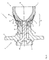
- FIG. 1 shows a sectional view through an exemplary embodiment of a bearing assembly according to the invention
- FIG. 11 shows an exploded drawing of the exemplary embodiment in
- FIGS. 12-14 show an illustration of the assembly of the exemplary embodiment in FIG. 10 ;
- FIGS. 15 , 16 show optimized forms of the intermediate ring in FIG. 10 ;
- FIGS. 1 and 2 each represent a bearing assembly 1 in longitudinal section, using the same reference numerals for identical parts.
- FIG. 1 represents an exemplary embodiment of a bearing assembly 1 in longitudinal section.
- the bearing assembly 1 comprises a wheel hub 2 of a motor vehicle (not shown).
- the wheel hub 2 is connected via a spur gear toothing 3 , 4 to a rotating joint or constant velocity joint 5 known in the art.
- the wheel hub 2 At one axial end the wheel hub 2 comprises a wheel flange 6 for receiving a rim of a vehicle wheel (not shown).
- a double-row rolling bearing 11 in the form of an angular-contact ball bearing is arranged in an O-arrangement on the wheel hub 2 .
- the rolling bearing 11 comprises an outer ring 12 , onto which a fixing flange 13 for a wheel carrier is formed, together with an inner ring 14 .
- Bearing balls 15 serving as rolling elements are arranged between the outer ring 12 and the inner ring 14 .
- the inner ring 14 comprises two bearing inner races 16 and 17 , an inner bearing inner race 16 situated axially on the wheel side relative to the longitudinal extent of the wheel hub 2 being integrally formed onto the wheel hub 2 , while an outer bearing inner race 17 situated axially on the transmission side is a separate component, which is pushed onto a stub shaft 18 of the wheel hub 2 .
- the outer, separate bearing inner race 17 situated axially on the transmission side has an inner end face 23 situated axially on the wheel side and an outer end face 24 situated axially on the transmission side, the latter being oriented towards a radial opposing or end face 25 of the joint body 7 and bearing against the latter.
- the bolt 22 is tightened the wheel hub 2 and the outer joint body 7 are moved axially towards one another until the spur gear toothing systems 3 , 4 intermesh with one another.
- the opposing face 25 of the joint body 7 presses against the outer end face 24 of the separate bearing inner race 17 situated axially on the transmission side and presses this bearing inner race 17 against a locating surface 26 of the inner bearing inner race 16 situated axially on the wheel side.
- this means 27 for the axial compensation of tolerances is an axial recess in the form of an annular groove 28 in the opposing face 25 of the end face 19 of the joint body 7 .
- the recess 28 ensures an elastic deformability in the area of the opposing face 25 , so that during assembly a contact free from play is achieved between the stub shaft 18 and the joint body 7 , first in the area of the end faces 24 , and then in the area of the spur gear toothing 3 , 4 .
- the required tolerance compensation for reliable bracing of the separate bearing inner race 17 in the rolling bearing 11 is ensured by the elastic deformability in the area where the joint body rests against the separate bearing inner race 17 .
- the journal 20 is of conically tapered design, so that the diameter of a front end area 29 of the journal 20 is smaller than the diameter of the journal 20 in the area of the transition to the toothing 4 .
- FIG. 2 shows a slightly different view of the bearing assembly 1 in FIG. 1 , showing joint balls 30 in the outer joint body 7 of the constant velocity joint 5 instead of the bolt 22 .
- the use of reference numerals has been largely abandoned in favor of an illustration of the diameters and widths through dimensioning lines and identification letters.
- the outside diameter D VER of the spur gear toothing 3 , 4 is smaller than or equal to the bore diameter D IR of the separate inner ring 14 , therefore D VER ⁇ D IR .
- the inside diameter D IVER of the spur gear toothing 3 , 4 is smaller by at least a factor of 0.95 than the outside diameter D VER of the spur gear toothing 3 , 4 , therefore D IVER ⁇ 0.95 ⁇ D VER .
- the row interval R AB of the bearing balls 15 is smaller than the outside diameter D VER of the spur gear toothing 3 , 4 , therefore R AB ⁇ D VER .
- the pitch diameter V TK of the spur gear toothing 3 , 4 is smaller than the pitch diameter GTK of the joint balls 30 therefore V TK ⁇ GTK.
- the outside diameter D VER of the spur gear toothing 3 , 4 is more than twice the diameter D W of the bearing balls 15 , therefore D VER >2 ⁇ D W .
- the inner ring cross section height IQ at the lowest point of the ball raceway is at least 0.2 times the diameter D W of the bearing balls 15 , therefore IQ ⁇ 0.2 ⁇ D.
- the diameter D 2 is therefore smaller than the diameter D 1 of the journal 20 on the joint side.
- the conically tapered design of the journal 20 has proven particularly advantageous. This makes it possible to increase the thread-bearing portion of the bolt 22 and in addition the conically tapered journal 20 of the outer joint body 7 facilitates assembly with the wheel hub 2 .
- the journal can now easily be introduced into the wheel hub 2 and due to the larger diameter has a self-centering action when introduced into the wheel hub 2 .
- the conically tapered geometry of the journal 20 helps to save weight.
- the toothing angle ⁇ may be arranged positively or negatively in relation to the plane of rotation of the bearing assembly 1 , and is preferably ⁇ 30°. It is particularly advantageous if the toothing angle ⁇ is inclined towards the outer joint body 7 , since this affords better inner ring bracing and a larger toothing width for transmitting torque.
- the spur gear toothing 3 , 4 of the wheel hub 2 and the constant velocity joint 5 is in each case embodied as Hirth toothing with teeth running radially, the number of teeth being between 12 and 60.
- the following figures show further exemplary embodiments of the means 27 for the axial compensation of tolerances of the two axial contact points, that is to say in the area of the spur gear toothing 3 , 4 and the contact of the opposing face 25 against the face edge 24 of the bearing inner race 17 .
- two force paths A, B are created, a first force path A running from the outer joint body 7 via the spur gear toothing 3 , 4 to the stub shaft 18 .
- a second force path B runs from the outer joint body 7 via the bearing inner race 17 to the wheel hub 2 .
- the two force paths A, B are therefore, at least in sections, designed to run kinematically parallel, especially at the contact points.
- the overall axial pre-tension generated by the tightening of the bolt 22 is divided according to the force paths A, B into a first pre-tension and a second pre-tension.
- FIG. 3 shows a somewhat modified representation of a further exemplary embodiment of a wheel bearing assembly 1 .
- the embodiment in FIG. 3 shows a more cylindrical journal 20 , which can also be replaced, however, by a conically tapered journal 20 according to the preceding figures.
- the various means 27 for the axial compensation of tolerances can also be used in the other embodiments.
- the means 27 is embodied as a circumferential rib 31 , which in the longitudinal section shown has a constant thickness.
- the rib 31 is inclined at an angle of approximately 10° in the direction of the bearing inner race 17 relative to a radial plane, which is aligned perpendicularly to the axis of rotation 32 of the bearing assembly. With its free end section this rib 31 bears circumferentially on the bearing inner race 17 .
- the rib 31 integrally formed onto the outer joint body 7 acts as a disk spring, which is connected to the outer joint body 7 .
- the rib 31 may also have elasto-plastic characteristics, the rib 31 in the fitted state being deformed elastically or elasto-plastically according to the design and configuration, so as to produce the optimum distribution of pre-tensioning forces between toothing 3 , 4 and bearing inner race 17 .
- FIG. 4 in a similar representation to FIG. 3 shows a further exemplary embodiment of the rib 31 , a recess 33 or a corresponding formed shape serving to form an elastic deformation area, so that the rib 31 is first elastically deformed on bracing of the outer joint body 7 and the wheel hub 2 .
- a plastic deformation of the rib 31 and the surrounding areas also ensues.
- FIG. 5 shows a further exemplary embodiment of a means 27 , the bearing inner race 17 in this embodiment having indentations 34 in an area facing the wheel hub 2 .
- the indentations 34 may be produced by recesses, for example, and have a circumferential corrugated or helical shape or they are embodied as parallel grooves.
- the recesses may be introduced internally or eternally and may be designed so that they increase towards the transmission side, for example.
- the bearing inner race 17 may be partially hardened, so that the means 27 behaves more elastically.
- the bearing inner race 17 may be fully hardened, so that the means 27 has more elasto-plastic characteristics.
- the bearing inner race 17 On subjecting the second force path B to a pre-tension, the bearing inner race 17 is first elastically compressed or deformed in the area of the indentations 34 and then plastically deformed or compressed in an axial direction.
- FIG. 6 shows a further embodiment of the invention, the means 27 being embodied as a circumferential V-shaped groove 35 in the bearing inner race 17 adjacent to the outer joint body 7 .
- the additional deformation travel provided by the means 27 is now arranged so that under deformation the position of the running surface 36 for the rolling elements on the bearing inner race 17 is not changed.
- the groove 35 is introduced on the outside of the bearing inner race 17 ; alternatively the groove may also be positioned on the inside. It is furthermore possible to introduce multiple grooves 35 or differently shaped grooves 35 .
- the bearing inner race 17 bears radially outwards only in a partial circumferential area, whereas a free space 37 is provided in a radially inner area.
- FIG. 7 shows a further exemplary embodiment of the means 27 , the means 27 in this exemplary embodiment being embodied as recesses 38 on the stub shaft 18 .
- the recesses 38 shown for creating a corrugated shape may also be designed asymmetrically thicker inwards/outwards or towards the transmission side.
- FIG. 9 shows a further exemplary embodiment of the invention, the intermediate ring 39 in this embodiment being arranged in the form of a compression ring between the outer joint body 7 and the bearing inner race 17 , so that this is inserted in the force path B.
- the intermediate ring 39 may be produced by a forming method such as deep drawing, for example. Different degrees of curvature in the intermediate ring 39 allow the behavior to be purposely controlled, thereby affording elastic and elasto-plastic deformation zones.
- FIG. 10 shows a further example of an intermediate ring 39 which in the longitudinal section shown is approximately V-shaped.
- the intermediate ring 39 represented may be produced by a chip-forming method (turning), for example; manufacture by means of rolling is also conceivable.
- the groove base of the V-shaped groove in the intermediate ring 39 serves for plasticization, whereas the legs are more elastically resilient.
- the intermediate ring 39 bears against the bearing inner race 17 on one side, and with the other side or with the other leg bears against a shoulder 40 of the outer joint body 7 .
- FIG. 11 shows the components of the wheel bearing assembly 1 with the intermediate ring 39 shown in FIG. 10 in a disengaged state. From this representation is can also be clearly seen that the stub shaft 18 in the end section is not expanded and in particular is designed so that the bearing inner race 17 can be drawn on and off.
- FIGS. 15 , 16 illustrate the degrees of freedom that are available for optimization of the intermediate element 39 as compensating element.
- Limiting the intermediate ring 39 to the horizontal lines saves ‘dead material’ and enhances the producability, since the ring can be better accommodated in a production machine.
- the lateral lines represent the possibility for making the legs thicker or thinner—either symmetrically or asymmetrically.
- the length of the legs may be varied by raising or lowering the base (middle) of the groove. It turns out here that increasing the width of the legs brings about a disproportionate increase in the rigidity of the intermediate ring 39 ; as a first approximation, a variation of the leg length has a linear effect on the rigidity.
- FIG. 16 shows a preferred, optimized form of the intermediate ring 39 .
- the faces on the outside and inside diameters are of cylindrical design for the sake of a good finish.
- fine adjustment of the intermediate ring 39 is advantageously undertaken via the leg length, that is to say through variation of the position of the groove base, a deep groove being chosen in a first variant V 1 and a shallow groove in a second variant V 2 .
- FIG. 17 shows a stress-strain diagram for two different materials for the loading of an intermediate ring 39 .
- the strain ⁇ (deltaL divided by L 0 ) is plotted on the X axis; the Y axis shows the stress ⁇ .
- the ultimate failure limit is entered at the points B, where a material failure of the intermediate ring 39 occurs.
- the working range 41 of the intermediate ring 39 is preferably placed into the range beyond the proportional, elastic range, that is to say where the material behavior moves into the plastic range and the curve runs flatter.
- the load limit is to be set at a safe interval from the fracture strain B. If the fracture strain is 8%, for example, the actual deformation should not exceed 4%.
- FIG. 18 derived from the content of FIG. 17 , represents the pre-tensioning force F of the bearing inner race 17 over the initial play S of the bearing assembly 1 due to tolerance.
- Initial play S is here taken to mean the distance in an axial direction between the mating toothing systems, when the outer joint body 7 via the intermediate ring 39 is up against the bearing inner race 17 . It is therefore the distance that has to be bridged by deformation in the compensating element 39 in order to bring the toothing into contact.
- the design range 41 only a very slight variation delta F in the pretension corresponds to a very large initial play delta S.
- the bearing inner race 17 can therefore be pre-tensioned with a maximum deviation of delta F.
- the bottom curve K 1 represents the profile of the pre-tensioning force for an element composed of 16MnCr5 having the geometry shown in FIG. 16 , variant V 1 .
- the middle curve K 2 corresponds to the profile for the same geometry but another material, that is to say C 56 .
- the top curve shows the profile of an intermediate ring 39 composed of C 56 according to FIG. 16 , variant 2 .
- Common to all three variants K 1 to K 3 is the fact that in the design or working range 41 the force increase runs very flat in the plastic range of the intermediate ring 39 .
- FIG. 19 represents an intermediate ring 39 in the form of an A-ring, as inverse variant of the V or U-ring.
- FIG. 20 shows a U-ring as an asymmetrical variant of the V-ring that allows a greater axial expansion.
- FIG. 21 shows an intermediate ring 39 in the form of an O-ring, a semi-finished tubular product in this application being bent as a ring.
- FIG. 22 shows an intermediate ring 39 in the form of a C-ring, the intermediate ring 39 in this variant bearing at two points on the outer joint body 7 . Like the variant shown, the open side may also face the bearing inner race 17 .
- FIG. 23 shows an intermediate ring 39 in the form of a W-ring, which is also conceivable in reverse form as an M-ring.
- FIG. 24 illustrates a T-ring, a variation with transverse T-bar to the outer joint body 7 also being possible. This variation affords a harder resilience than the preceding variants.
- An X-ring construction with crossed legs is also possible.
- FIG. 25 shows an N-ring, also referred to as an S-ring or Z-ring. The leg against the bearing inner race 17 can also rest against the inside diameter. Due to the geometry this design is softer than the V-ring but harder then the W-ring.
- the embodiment in FIG. 26 shows a corrugated ring, which is particularly suited to very large axial expansions, but takes up little overall radial space.
- a variant turned through 90°, in which the corrugated bearing inner race respectively stands against the outer joint body 7 is also conceivable.
- the means 27 may be embodied as a purely elastic element.
- the means 27 is embodied as an elasto-plastic means, which by means of the shallow increase in force in the plastic range described above produces a low dispersion of pre-tensioning force.
- the tolerance chain gives rise to a dimensional uncertainty of up to 0.3 mm; in a correlation with the spring rigidity of an elastic element this can lead to an inadmissible dispersion of the tensioning force acting on the bearing inner race 17 .
- the elasto-plastic element which reduces the dispersion, is to be preferred.
- the elastic or elasto-plastic element may be both integrally formed on and embodied as a separate element or component.
- An advantage to the embodiment as a separate element is the replaceability of the joint cap 7 and the outer joint body or bearing 17 , without also having to replace the other component in each instance. It is merely necessary to use a new compensating element 39 .
Landscapes
- Engineering & Computer Science (AREA)
- Mechanical Engineering (AREA)
- General Engineering & Computer Science (AREA)
- Rolling Contact Bearings (AREA)
Abstract
Description
- DVER: outside diameter of the
spur gear toothing - DIR: bore diameter of the separate
inner ring 14 - DIVER: inside diameter of the
spur gear toothing - RAB: row interval of the bearing
balls 15 - IRB: width of the separate bearing
inner race 17 - VTK: pitch diameter of the
spur gear toothing - GTK: pitch diameter of the
joint balls 30 - LZ: distance of the
wheel hub 2, at the center line of the transmission-side ball row, from the addendum circle of thespur gear toothing 4 - DW: diameter of the bearing
ball 15 - IQ: cross section height at the lowest point of the ball raceway of the separate bearing
inner race 17 - D1: diameter of the
journal 20 in the area of the transition to the inside diameter DIVER of thespur gear toothing - D2: diameter of the
journal 20 in the area of its front, wheelside end area 29 - β: toothing angle of the
spur gear toothing
- 1 Bearing assembly
- 2 Wheel hub
- 3 Spur gear toothing
- 4 Spur gear toothing
- 5 Rotating joint or constant velocity joint
- 6 Wheel flange
- 7 Outer joint body
- 8 Raceway
- 11 Rolling bearing
- 12 Outer ring
- 13 Fixing flange
- 14 Inner ring
- 15 Bearing ball
- 16 Bearing inner race
- 17 Bearing inner race
- 18 Stub shaft
- 19 End face
- 20 Journal
- 21 Bore
- 22 Bolt
- 23 End face
- 24 End face
- 25 Race/opposing face
- 26 Locating surface
- 27 Means, recess
- 28 Annular groove
- 29 Front end area of the
journal 20 - 30 Joint ball
- 31 Rib
- 32 Axis of rotation
- 33 Recess
- 34 Indentations, recesses
- 35 Groove
- 36 Running surface
- 37 Free space
- 38 Recess
- 39 Intermediate ring
- 40 Shoulder
- 41 Design range
- DVER: outside diameter of the
spur gear toothing - DIR: bore diameter of the separate
inner ring 14 - DIVER: inside diameter of the
spur gear toothing - RAB: row interval of the bearing
balls 15 - IRB: width of the separate bearing
inner race 17 - VTK: pitch diameter of the
spur gear toothing - GTK: pitch diameter of the
joint balls 30 - LZ: distance of the
wheel hub 2, at the center line of the transmission-side ball row, from the addendum circle of thespur gear toothing 4 - DW: diameter of the bearing
ball 15 - IQ: cross section height at the lowest point of the ball raceway of the separate bearing
inner race 17 - D1: diameter of the
journal 20 in the area of the transition to the inside diameter DIVER of thespur gear toothing - D2: diameter of the
journal 20 in the area of its front, wheelside end area 29 - β: toothing angle of the
spur gear toothing
Claims (34)
Applications Claiming Priority (4)
| Application Number | Priority Date | Filing Date | Title |
|---|---|---|---|
| DE102007016427 | 2007-04-05 | ||
| DE102007016427.2 | 2007-04-05 | ||
| DE102007016427A DE102007016427B4 (en) | 2007-04-05 | 2007-04-05 | Bearing arrangement of a driven via a rotary hub of a motor vehicle |
| PCT/DE2008/000577 WO2008122277A2 (en) | 2007-04-05 | 2008-04-04 | Wheel bearing assembly |
Publications (2)
| Publication Number | Publication Date |
|---|---|
| US20100119185A1 US20100119185A1 (en) | 2010-05-13 |
| US8439572B2 true US8439572B2 (en) | 2013-05-14 |
Family
ID=39650663
Family Applications (1)
| Application Number | Title | Priority Date | Filing Date |
|---|---|---|---|
| US12/594,362 Expired - Fee Related US8439572B2 (en) | 2007-04-05 | 2008-04-04 | Wheel bearing assembly |
Country Status (3)
| Country | Link |
|---|---|
| US (1) | US8439572B2 (en) |
| DE (1) | DE102007016427B4 (en) |
| WO (2) | WO2008122271A1 (en) |
Cited By (4)
| Publication number | Priority date | Publication date | Assignee | Title |
|---|---|---|---|---|
| US20130230351A1 (en) * | 2012-03-02 | 2013-09-05 | Jtekt Corporation | Spline forming method for hub unit, hub unit, spline forming method for joint, and joint |
| US20230043527A1 (en) * | 2021-08-05 | 2023-02-09 | Aktiebolaget Skf | Subassembly including a wheel hub and a constant velocity joint |
| US12078205B2 (en) | 2020-01-24 | 2024-09-03 | Ntn-Snr Roulements | Motor vehicle wheel assembly |
| US12196265B2 (en) | 2020-01-24 | 2025-01-14 | Ntn-Snr Roulements | Rotating assembly, in particular for guiding a motor vehicle wheel |
Families Citing this family (15)
| Publication number | Priority date | Publication date | Assignee | Title |
|---|---|---|---|---|
| EP2749779B1 (en) | 2007-07-04 | 2017-06-28 | Nsk Ltd. | Assembling method of bearing unit |
| EP2105321B1 (en) * | 2008-03-28 | 2013-03-20 | JTEKT Corporation | Wheel bearing assembly, and manufacturing method thereof |
| DE102010013937A1 (en) * | 2010-04-06 | 2011-10-06 | Schaeffler Technologies Gmbh & Co. Kg | Wheel bearing for a vehicle |
| DE102010026858A1 (en) | 2010-07-12 | 2012-01-12 | Schaeffler Technologies Gmbh & Co. Kg | Wheel bearing joint unit for motor car, has gearing and counter teeth braced against each other by screwing element, screw thread supported into hub at joint component over head, and head pre-tensioned over rotation axis of inclined surface |
| DE102012204795A1 (en) * | 2012-03-26 | 2013-09-26 | Schaeffler Technologies AG & Co. KG | Wheel hub motor with equipotential bonding |
| DE102013203005A1 (en) | 2013-02-25 | 2014-08-28 | Schaeffler Technologies Gmbh & Co. Kg | Wheel bearing unit for axle of vehicle i.e. motor car, has hub flange-side seal part supported at seal running radius of wheel bearing hub, where seal running radius exceeds raceway radius of rolling element series |
| DE102013205340B3 (en) * | 2013-03-26 | 2014-07-10 | Schaeffler Technologies Gmbh & Co. Kg | Wheel bearing unit of vehicle axle, has bearing hub which is associated with resilient expansion sleeve cooperating with joint bell, and supply port is provided for releasing clamping screw to tooth in gap position of front serrations |
| DE102013022208A1 (en) | 2013-12-21 | 2015-06-25 | GM Global Technology Operations LLC (n. d. Gesetzen des Staates Delaware) | Bearing arrangement for mounting a wheel hub, motor vehicle |
| DE102014203206A1 (en) | 2014-02-24 | 2015-08-27 | Schaeffler Technologies AG & Co. KG | Riveted wheel bearing unit with improved clamping force |
| GB2517533B (en) * | 2014-03-26 | 2016-05-25 | Rolls Royce Plc | A shaft clamp assembly and a method of using the same |
| US11371555B2 (en) * | 2017-11-10 | 2022-06-28 | Volvo Truck Corporation | Transmission input shaft arrangement |
| DE102019124784B4 (en) | 2019-09-16 | 2022-02-24 | Schaeffler Technologies AG & Co. KG | Wheel hub pivot assembly |
| DE102021104926B3 (en) | 2021-03-02 | 2022-04-14 | Audi Aktiengesellschaft | Wheel bearing arrangement of a motor vehicle and motor vehicle |
| CN115055921A (en) * | 2022-06-29 | 2022-09-16 | 山西柴油机工业有限责任公司 | Process method for strengthening bimetal machining surface of bottom hole of engine crankshaft |
| DE102024206270A1 (en) * | 2024-07-03 | 2026-01-08 | Zf Friedrichshafen Ag | Wheel head with overload protection and vehicle |
Citations (10)
| Publication number | Priority date | Publication date | Assignee | Title |
|---|---|---|---|---|
| US3009742A (en) * | 1958-09-08 | 1961-11-21 | Kronprinz Ag | Wheel assemblies |
| DE2543210A1 (en) | 1974-09-30 | 1976-04-08 | Skf Kugellagerfabriken Gmbh | FORMAL CONNECTION BETWEEN A ROLLING BEARING UNIT AND A SHAFT |
| DE3116720C1 (en) | 1981-04-28 | 1982-10-28 | Loehr & Bromkamp Gmbh | Bearing arrangement of a wheel hub which can be driven via a constant-velocity rotary joint |
| US4493388A (en) * | 1981-04-28 | 1985-01-15 | Lohr & Bromkamp Gmbh | Bearing assembly for a vehicle wheel driven by a rotary constant velocity universal joint |
| DE3636243A1 (en) | 1986-10-24 | 1988-05-11 | Loehr & Bromkamp Gmbh | WHEEL BEARING (NY) SMOOTH JOINT UNIT |
| US5806936A (en) * | 1995-09-18 | 1998-09-15 | Gkn Glaenzer Spicer | Drive-wheel hub for a motor vehicle |
| US6146022A (en) | 1997-12-25 | 2000-11-14 | Ntn Corporation | Hub unit bearing for wheel |
| DE10338172B3 (en) | 2003-08-20 | 2005-06-23 | Gkn Driveline Deutschland Gmbh | Hub universal joint assembly |
| DE102005018126A1 (en) | 2005-04-20 | 2006-10-26 | Schaeffler Kg | Wheel bearing joint unit |
| WO2007054190A1 (en) | 2005-11-11 | 2007-05-18 | Gkn Driveline Deutschland Gmbh | Wheel hub/rotary joint arrangement having a spur toothing system |
Family Cites Families (8)
| Publication number | Priority date | Publication date | Assignee | Title |
|---|---|---|---|---|
| DE3219747A1 (en) * | 1982-05-26 | 1983-12-01 | Skf Kugellagerfabriken Gmbh, 8720 Schweinfurt | Positive connection between an input shaft and a rolling bearing unit |
| DE3604630A1 (en) * | 1986-02-14 | 1987-08-27 | Loehr & Bromkamp Gmbh | STORAGE ARRANGEMENT |
| DE4210461C2 (en) * | 1992-03-30 | 1995-08-31 | Loehr & Bromkamp Gmbh | Wheel hub swivel arrangement |
| DE102005009938B4 (en) * | 2005-03-04 | 2012-07-12 | Schaeffler Technologies Gmbh & Co. Kg | Spur toothing for a drivable hub |
| DE102005009935A1 (en) * | 2005-03-04 | 2006-09-07 | Schaeffler Kg | Wheel bearing arrangement with spur toothing |
| DE102005016427A1 (en) * | 2005-04-08 | 2006-10-12 | Schaeffler Kg | Bund with frontal teeth for a drivable hub |
| DE102005018127A1 (en) * | 2005-04-20 | 2006-10-26 | Schaeffler Kg | Spur toothing on a coupling element for transmitting torques |
| DE102005036659A1 (en) * | 2005-08-04 | 2007-02-08 | Schaeffler Kg | Wheel bearing arrangement with spur toothing |
-
2007
- 2007-04-05 DE DE102007016427A patent/DE102007016427B4/en not_active Expired - Fee Related
-
2008
- 2008-04-01 WO PCT/DE2008/000551 patent/WO2008122271A1/en not_active Ceased
- 2008-04-04 US US12/594,362 patent/US8439572B2/en not_active Expired - Fee Related
- 2008-04-04 WO PCT/DE2008/000577 patent/WO2008122277A2/en not_active Ceased
Patent Citations (13)
| Publication number | Priority date | Publication date | Assignee | Title |
|---|---|---|---|---|
| US3009742A (en) * | 1958-09-08 | 1961-11-21 | Kronprinz Ag | Wheel assemblies |
| DE2543210A1 (en) | 1974-09-30 | 1976-04-08 | Skf Kugellagerfabriken Gmbh | FORMAL CONNECTION BETWEEN A ROLLING BEARING UNIT AND A SHAFT |
| US4047770A (en) * | 1974-09-30 | 1977-09-13 | Skf Industrial Trading And Development Company, B.V. | Hub bearing unit assembly |
| DE3116720C1 (en) | 1981-04-28 | 1982-10-28 | Loehr & Bromkamp Gmbh | Bearing arrangement of a wheel hub which can be driven via a constant-velocity rotary joint |
| US4460058A (en) * | 1981-04-28 | 1984-07-17 | Lohr & Bromkamp Gmbh | Bearing assembly for a wheel hub driven by a rotary constant velocity universal joint |
| US4493388A (en) * | 1981-04-28 | 1985-01-15 | Lohr & Bromkamp Gmbh | Bearing assembly for a vehicle wheel driven by a rotary constant velocity universal joint |
| DE3636243A1 (en) | 1986-10-24 | 1988-05-11 | Loehr & Bromkamp Gmbh | WHEEL BEARING (NY) SMOOTH JOINT UNIT |
| US4893960A (en) * | 1986-10-24 | 1990-01-16 | Lohr & Bromkamp Gmbh | Wheel Bearing/constant velocity joint unit |
| US5806936A (en) * | 1995-09-18 | 1998-09-15 | Gkn Glaenzer Spicer | Drive-wheel hub for a motor vehicle |
| US6146022A (en) | 1997-12-25 | 2000-11-14 | Ntn Corporation | Hub unit bearing for wheel |
| DE10338172B3 (en) | 2003-08-20 | 2005-06-23 | Gkn Driveline Deutschland Gmbh | Hub universal joint assembly |
| DE102005018126A1 (en) | 2005-04-20 | 2006-10-26 | Schaeffler Kg | Wheel bearing joint unit |
| WO2007054190A1 (en) | 2005-11-11 | 2007-05-18 | Gkn Driveline Deutschland Gmbh | Wheel hub/rotary joint arrangement having a spur toothing system |
Cited By (4)
| Publication number | Priority date | Publication date | Assignee | Title |
|---|---|---|---|---|
| US20130230351A1 (en) * | 2012-03-02 | 2013-09-05 | Jtekt Corporation | Spline forming method for hub unit, hub unit, spline forming method for joint, and joint |
| US12078205B2 (en) | 2020-01-24 | 2024-09-03 | Ntn-Snr Roulements | Motor vehicle wheel assembly |
| US12196265B2 (en) | 2020-01-24 | 2025-01-14 | Ntn-Snr Roulements | Rotating assembly, in particular for guiding a motor vehicle wheel |
| US20230043527A1 (en) * | 2021-08-05 | 2023-02-09 | Aktiebolaget Skf | Subassembly including a wheel hub and a constant velocity joint |
Also Published As
| Publication number | Publication date |
|---|---|
| WO2008122271A1 (en) | 2008-10-16 |
| US20100119185A1 (en) | 2010-05-13 |
| WO2008122277A2 (en) | 2008-10-16 |
| WO2008122277A3 (en) | 2009-01-08 |
| DE102007016427B4 (en) | 2010-11-25 |
| DE102007016427A1 (en) | 2008-10-16 |
Similar Documents
| Publication | Publication Date | Title |
|---|---|---|
| US8439572B2 (en) | Wheel bearing assembly | |
| US6749517B2 (en) | Wheel drive unit | |
| US6488589B2 (en) | Apparatus for driving wheel of automobile | |
| US20080175526A1 (en) | Face Spline For a Driven Wheel Hub | |
| KR101312786B1 (en) | Wheel bearing arrangement having spur toothing | |
| US8608444B2 (en) | Single-bearing structure and wind power plant having the single-bearing structure | |
| US9903413B2 (en) | Pinion bearing unit | |
| US8052332B2 (en) | Wheel bearing assembly, and manufacturing method thereof | |
| US9005043B2 (en) | Wheel supporting device | |
| EP1398181B1 (en) | Bearing apparatus for a wheel of a vehicle | |
| JP2007046703A (en) | Bearing device for driving wheel | |
| JP2013141861A (en) | Bearing device for wheel | |
| US20210088119A1 (en) | Toothing Arrangement | |
| CN116981855A (en) | Wheel bearing device | |
| CN117015669A (en) | Wheel bearing device | |
| WO2007125654A1 (en) | Bearing device for drive wheel, and its manufacturing method | |
| US9162526B2 (en) | Wheel support device | |
| JP2005219650A (en) | Bearing device for driving wheel | |
| JP2007326503A (en) | Bearing device for driving wheel | |
| JP2007290591A (en) | Bearing device for driving wheel | |
| JP2005081869A (en) | Drive wheel hub unit | |
| JP2007307994A (en) | Bearing device for wheel | |
| DE102015217082A1 (en) | Wheel hub assembly for a driven vehicle axle and PTO shaft thereto | |
| JP2007290587A (en) | Bearing device for driving wheel | |
| JP2007290588A (en) | Bearing device for driving wheel |
Legal Events
| Date | Code | Title | Description |
|---|---|---|---|
| AS | Assignment |
Owner name: SCHAEFFLER KG,GERMANY Free format text: ASSIGNMENT OF ASSIGNORS INTEREST;ASSIGNORS:FISCHER, RAPHAEL;NIEBLING, PETER;LANGER, ROLAND;AND OTHERS;SIGNING DATES FROM 20091006 TO 20091012;REEL/FRAME:023533/0734 Owner name: SCHAEFFLER KG, GERMANY Free format text: ASSIGNMENT OF ASSIGNORS INTEREST;ASSIGNORS:FISCHER, RAPHAEL;NIEBLING, PETER;LANGER, ROLAND;AND OTHERS;SIGNING DATES FROM 20091006 TO 20091012;REEL/FRAME:023533/0734 |
|
| AS | Assignment |
Owner name: SCHAEFFLER TECHNOLOGIES GMBH & CO. KG, GERMANY Free format text: ASSIGNMENT OF ASSIGNORS INTEREST;ASSIGNOR:SCHAEFFLER KG;REEL/FRAME:028523/0790 Effective date: 20100128 |
|
| AS | Assignment |
Owner name: SCHAEFFLER TECHNOLOGIES AG & CO. KG, GERMANY Free format text: CHANGE OF NAME;ASSIGNOR:SCHAEFFLER TECHNOLOGIES GMBH & CO. KG;REEL/FRAME:028533/0036 Effective date: 20120119 |
|
| STCF | Information on status: patent grant |
Free format text: PATENTED CASE |
|
| CC | Certificate of correction | ||
| AS | Assignment |
Owner name: SCHAEFFLER TECHNOLOGIES AG & CO. KG, GERMANY Free format text: CHANGE OF NAME;ASSIGNOR:SCHAEFFLER TECHNOLOGIES GMBH & CO. KG;REEL/FRAME:037732/0347 Effective date: 20150101 Owner name: SCHAEFFLER TECHNOLOGIES GMBH & CO. KG, GERMANY Free format text: MERGER AND CHANGE OF NAME;ASSIGNORS:SCHAEFFLER TECHNOLOGIES AG & CO. KG;SCHAEFFLER VERWALTUNGS 5 GMBH;REEL/FRAME:037732/0228 Effective date: 20131231 |
|
| AS | Assignment |
Owner name: SCHAEFFLER TECHNOLOGIES AG & CO. KG, GERMANY Free format text: CORRECTIVE ASSIGNMENT TO CORRECT THE PROPERTY NUMBERS PREVIOUSLY RECORDED ON REEL 037732 FRAME 0347. ASSIGNOR(S) HEREBY CONFIRMS THE APP. NO. 14/553248 SHOULD BE APP. NO. 14/553258;ASSIGNOR:SCHAEFFLER TECHNOLOGIES GMBH & CO. KG;REEL/FRAME:040404/0530 Effective date: 20150101 |
|
| FPAY | Fee payment |
Year of fee payment: 4 |
|
| FEPP | Fee payment procedure |
Free format text: MAINTENANCE FEE REMINDER MAILED (ORIGINAL EVENT CODE: REM.); ENTITY STATUS OF PATENT OWNER: LARGE ENTITY |
|
| LAPS | Lapse for failure to pay maintenance fees |
Free format text: PATENT EXPIRED FOR FAILURE TO PAY MAINTENANCE FEES (ORIGINAL EVENT CODE: EXP.); ENTITY STATUS OF PATENT OWNER: LARGE ENTITY |
|
| STCH | Information on status: patent discontinuation |
Free format text: PATENT EXPIRED DUE TO NONPAYMENT OF MAINTENANCE FEES UNDER 37 CFR 1.362 |
|
| FP | Lapsed due to failure to pay maintenance fee |
Effective date: 20210514 |