US8438677B2 - Caster arrangement for a bariatric lift device - Google Patents
Caster arrangement for a bariatric lift device Download PDFInfo
- Publication number
- US8438677B2 US8438677B2 US12/788,765 US78876510A US8438677B2 US 8438677 B2 US8438677 B2 US 8438677B2 US 78876510 A US78876510 A US 78876510A US 8438677 B2 US8438677 B2 US 8438677B2
- Authority
- US
- United States
- Prior art keywords
- caster
- assembly
- elongated leg
- patient
- longitudinal axis
- Prior art date
- Legal status (The legal status is an assumption and is not a legal conclusion. Google has not performed a legal analysis and makes no representation as to the accuracy of the status listed.)
- Active, expires
Links
Images


Classifications
-
- A—HUMAN NECESSITIES
- A61—MEDICAL OR VETERINARY SCIENCE; HYGIENE
- A61G—TRANSPORT, PERSONAL CONVEYANCES, OR ACCOMMODATION SPECIALLY ADAPTED FOR PATIENTS OR DISABLED PERSONS; OPERATING TABLES OR CHAIRS; CHAIRS FOR DENTISTRY; FUNERAL DEVICES
- A61G7/00—Beds specially adapted for nursing; Devices for lifting patients or disabled persons
- A61G7/10—Devices for lifting patients or disabled persons, e.g. special adaptations of hoists thereto
- A61G7/104—Devices carried or supported by
- A61G7/1046—Mobile bases, e.g. having wheels
-
- A—HUMAN NECESSITIES
- A61—MEDICAL OR VETERINARY SCIENCE; HYGIENE
- A61G—TRANSPORT, PERSONAL CONVEYANCES, OR ACCOMMODATION SPECIALLY ADAPTED FOR PATIENTS OR DISABLED PERSONS; OPERATING TABLES OR CHAIRS; CHAIRS FOR DENTISTRY; FUNERAL DEVICES
- A61G2200/00—Information related to the kind of patient or his position
- A61G2200/10—Type of patient
- A61G2200/16—Type of patient bariatric, e.g. heavy or obese
-
- A—HUMAN NECESSITIES
- A61—MEDICAL OR VETERINARY SCIENCE; HYGIENE
- A61G—TRANSPORT, PERSONAL CONVEYANCES, OR ACCOMMODATION SPECIALLY ADAPTED FOR PATIENTS OR DISABLED PERSONS; OPERATING TABLES OR CHAIRS; CHAIRS FOR DENTISTRY; FUNERAL DEVICES
- A61G7/00—Beds specially adapted for nursing; Devices for lifting patients or disabled persons
- A61G7/10—Devices for lifting patients or disabled persons, e.g. special adaptations of hoists thereto
- A61G7/1013—Lifting of patients by
- A61G7/1015—Cables, chains or cords
-
- A—HUMAN NECESSITIES
- A61—MEDICAL OR VETERINARY SCIENCE; HYGIENE
- A61G—TRANSPORT, PERSONAL CONVEYANCES, OR ACCOMMODATION SPECIALLY ADAPTED FOR PATIENTS OR DISABLED PERSONS; OPERATING TABLES OR CHAIRS; CHAIRS FOR DENTISTRY; FUNERAL DEVICES
- A61G7/00—Beds specially adapted for nursing; Devices for lifting patients or disabled persons
- A61G7/10—Devices for lifting patients or disabled persons, e.g. special adaptations of hoists thereto
- A61G7/1013—Lifting of patients by
- A61G7/1017—Pivoting arms, e.g. crane type mechanisms
Definitions
- This invention relates in general to patient lifting and transferring.
- the invention relates to a device for lifting a patient from a bed or some other apparatus (wheelchair, bath, etc.) and permitting the patient to be readily moved.
- a lifting hoist typically includes a sling for supporting a patient.
- the sling may be lifted by a movable arm.
- the patient In a lifting hoist, the patient is typically completely supported from an overhead position and has no active role in supporting himself.
- a lifting hoist is commonly used to temporarily raise a patient or transport the patient without discomfort.
- the lifting hoist In order for a lifting hoist to be used to transport a supported patient, the lifting hoist typically includes wheels or casters. These casters allow the attendant to roll the lifting hoist on the support surface while the patient is supported in the sling.
- the patient lift includes a base and a mast extending from the base.
- the patient lift also includes a first elongated leg having a first longitudinal axis extending from the base.
- a first caster assembly is mounted for pivotal movement relative to the first elongated leg about a first carriage axis.
- the first caster assembly includes a first caster truck and a plurality of first assembly casters mounted to the first caster truck.
- the patient lift also includes a second elongated leg having a second longitudinal axis extending from the base.
- a second caster assembly is mounted for pivotal movement relative to the second elongated leg about a second carriage axis.
- the second caster assembly includes a second caster truck and a plurality of second assembly casters mounted to the second caster truck.
- This invention further relates to a patient lift including a base and a mast adapted to support a patient load extending from the base in a first direction.
- the patient lift includes an elongated leg with a longitudinal axis extending from the base.
- a rear caster is mounted to the base or the elongated leg and is adapted to support the base relative to a support surface.
- a caster assembly is mounted relative to the elongated leg.
- the caster assembly includes a plurality of assembly casters adapted to support the elongated leg relative to the support surface.
- the caster assembly is adapted to maintain the plurality of assembly casters in contact with the support surface when the mast is supporting the patient load and when the mast is not supporting the patient load.
- This invention further relates to a patient lift that includes a base and a mast that extends from the base in a first direction.
- the mast is adapted to support a patient load.
- the patient lift includes a first elongated leg having a first longitudinal axis extending from the base in a forward direction.
- the first elongated leg is mounted for pivotal movement relative to the base wherein the first longitudinal axis remains substantially parallel to a support surface.
- the patient lift also includes a first caster assembly mounted for pivotal movement relative to the first elongated leg.
- the first caster assembly includes a plurality of first assembly casters adapted to support the first elongated leg relative to the support surface.
- the plurality of first assembly casters includes a first rearward assembly caster and a first forward assembly caster located farther from the base along the first longitudinal axis than the first rearward assembly caster.
- the first caster assembly is adapted so that when the mast is supporting the patient load the first elongated leg is elastically deformed and first caster assembly maintains the plurality of first assembly casters in contact with the support surface.
- the patient lift also includes a second elongated leg having a second longitudinal axis extending from the base in a forward direction. The second elongated leg is mounted for pivotal movement relative to the base wherein the second longitudinal axis remains substantially parallel to a support surface.
- the patient lift also includes a second caster assembly mounted for pivotal movement relative to the second elongated leg.
- the second caster assembly includes a plurality of second assembly casters adapted to support the second elongated leg relative to the support surface.
- the plurality of second assembly casters includes a second rearward assembly caster and a second forward assembly caster located farther from the base along the second longitudinal axis than the second rearward assembly caster.
- the second caster assembly is adapted so that when the mast is supporting the patient load the second elongated leg is elastically deformed and second caster assembly maintains the plurality of second assembly casters in contact with the support surface.
- the patient lift also includes a rear caster mounted relative to one of the base, the first elongated leg and the second elongated leg.
- the rear caster is adapted to support the base relative to the support surface.
- the base, first elongated leg and second elongated leg are adapted so that the first longitudinal axis is substantially coplanar with the second longitudinal axis.
- FIG. 1 is a perspective view of a patient lift.
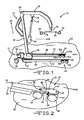
- FIG. 2 is a perspective view of a distil end of an elongated leg and a caster assembly of the patient lift of FIG. 1 .
- FIG. 3 is a schematic view, taken from the side, of the patient lift of FIG. 1 , illustrating the patient lift in an unloaded state.
- FIG. 4 is a schematic view similar to that shown in FIG. 3 , illustrating the patient lift in a loaded state.
- FIG. 5 is a schematic view of a loaded lift that is equipped with a prior art caster array.
- FIG. 6 is a side view of the caster assembly of the patient lift of FIG. 4 , illustrating the forces on the caster assembly.
- FIG. 1 one embodiment of a patient lift 10 .
- the illustrated patient lift 10 is a patient lifting hoist.
- the patient lift 10 includes a base assembly indicated generally at 12 , and a mast assembly indicated generally at 14 .
- the components of the patient lift 10 may be made of metal, plastic, or other desired materials.
- the base assembly 12 includes a base 16 .
- the base assembly 12 also includes a first elongated leg 18 and a second elongated leg 20 that extend from the base 16 .
- the first elongated leg 18 and the second elongated leg 20 on the illustrated patient lift 10 are substantially similar to each other, and may be interchangeable. In other embodiments the elongated legs may be different from one other. For example, the legs may be of different lengths or have different cross sectional shapes.
- the first elongated leg includes a first longitudinal axis 22 .
- the second elongated leg includes a second longitudinal axis 24 .
- the first elongated leg 18 and the second elongated leg 20 extend from the base 16 generally in a forward direction, indicated by the arrow 26 .
- the first elongated leg 18 and the second elongated leg 20 are attached to the base 16 at a first leg hinge 28 and a second leg hinge (not visible in FIG. 1 ), respectively.
- the first leg hinge 28 and the second leg hinge allow the first elongated leg 18 and the second elongated leg 20 to pivot relative to the base 16 .
- the first leg hinge 28 and the second leg hinge allow the first leg 18 and the second leg 20 to be positioned such that the first longitudinal axis 22 and the second longitudinal axis 24 are parallel to each other.
- first leg hinge 28 and the second leg hinge allow the first leg 18 and the second leg 20 to be positioned such that the first longitudinal axis 22 and the second longitudinal axis 24 are not parallel to each other.
- first longitudinal axis 22 and the second longitudinal axis 24 will be substantially coplanar. It should be appreciated that the patient lift 10 may be adapted so that the first longitudinal axis 22 and the second longitudinal axis 24 may be moved into non-coplanar positions, if desired.
- the base assembly 12 includes a pair of rear casters 32 and 34 .
- the illustrated rear casters 32 and 34 are mounted for pivotal movement relative to the first elongated leg 18 and the second elongated leg 20 , respectively. It should be appreciated that the rear casters 32 and 34 may alternatively be mounted relative to the base 16 .
- the illustrated rear casters 32 and 34 are locking casters; however, other desired types of casters may be used on the patient lift 10 .
- the base assembly 12 may include fewer than or more than the two rear casters 32 and 34 illustrated. For example, the patient lift 10 may have a single rear wheel mounted relative to the base 16 .
- the base assembly 12 also includes a first caster assembly indicated at 36 and a second caster assembly indicated at 38 .
- the first caster assembly 36 and the second caster assembly 38 are mounted relative to the first elongated leg 18 and the second elongated leg 20 , respectively.
- the first caster assembly 36 is shown in greater detail in FIG. 2 .
- the first caster assembly 36 includes a first caster truck 40 .
- the first caster truck 40 is mounted for pivotal movement relative to the first elongated leg 18 .
- the first elongated leg 18 includes a fork with two tines 42 and 44 .
- the first caster truck 40 includes a tongue 46 .
- the tongue 46 is received between the tines 42 and 44 of the fork.
- a pivot pin 48 extends through the tines 42 and 44 and the tongue 46 .
- the first caster truck 40 is then able to be pivoted relative to the first elongated leg 18 about a carriage axis 50 that extends through the pivot pin 48 .
- the carriage axis 50 is substantially perpendicular to the first longitudinal axis 22 . It should be appreciated that the carriage axis 50 may be situated to be other than substantially perpendicular to the first longitudinal axis 22 .
- the first caster assembly 36 includes a forward assembly caster 52 and a rearward assembly caster 54 . It should be appreciated that the forward assembly caster 52 is located farther in the forward direction 26 than the rearward assembly caster 54 . This also means that the forward assembly caster 52 is located farther from the base 16 along the first longitudinal axis 22 than the rearward assembly caster 54 . In the illustrated embodiment, the forward assembly caster 52 and the rearward assembly caster 54 are the same size. However, any desired combination of sizes of casters may be used. Additionally, it should be appreciated that more than the two casters illustrated on the first caster assembly 36 may be used, if desired.
- the forward assembly caster 52 is mounted relative to the first caster truck 40 at a forward assembly caster mounting point 56 .
- the rearward assembly caster 54 is mounted relative to the first caster truck 40 at a rearward assembly caster mounting point 58 .
- the forward assembly caster mounting point 56 is located on a forward side of the carriage axis 50 while the rearward assembly caster mounting point 58 is located on a rearward side of the carriage axis 50 .
- the forward assembly caster mounting point 56 and the rearward assembly caster mounting point 58 are located equidistantly from the carriage axis 50 . It should be appreciated that the caster mounting points may be located different distances from the carriage axis 50 .
- the forward assembly caster mounting point 56 and the rearward assembly caster mounting point 58 are located in line with the first longitudinal axis 22 . However, it should be appreciated that the forward assembly caster mounting point 56 and the rearward assembly caster mounting point 58 may be off set from the first longitudinal axis 22 , if desired.
- the second caster assembly 38 mounted relative to the second elongated leg 20 is substantially similar to the first caster assembly 36 .
- the mounting of the second caster assembly 38 to the second elongate leg 20 will not be described in detail.
- the second caster assembly 38 includes a second caster truck 40 a .
- the second caster truck 40 a is mounted for pivotal movement relative to the second elongated leg 20 .
- the second caster truck 40 a is able to be pivoted relative to the second elongated leg 20 about a second carriage axis 50 a .
- the second carriage axis 50 a is substantially perpendicular to the second longitudinal axis 24 . It should be appreciated that the second carriage axis 50 a may be situated to be other than substantially perpendicular to the second longitudinal axis 24 .
- the second caster assembly 38 also includes forward assembly caster 52 a and a rearward assembly caster 54 a . It should be appreciated that the forward assembly caster 52 a is located farther in the forward direction 26 than the rearward assembly caster 54 a . This also means that the forward assembly caster 52 a is located farther from the base 16 along the second longitudinal axis 24 than the rearward assembly caster 54 a . In the illustrated embodiment, the forward assembly caster 52 a and the rearward assembly caster 54 a are the same size. However, any desired combination of sizes of casters may be used. Additionally, it should be appreciated that more than the two casters illustrated on the second caster assembly 38 may be used, if desired.
- the rear casters 32 and 34 and the casters on the first caster assembly 36 and the second caster assembly 38 are adapted to support the patient lift 10 relative to a support surface, such as the floor or the ground, indicated at 60 . Therefore, the illustrated patient lift 10 is supported relative the support surface 60 by the rear casters 32 and 34 , the forward assembly casters 52 and 52 a , and the rearward assembly casters 54 and 54 a.
- the mast assembly of the patient lift 10 includes a mast 62 .
- the mast 62 is mounted on the base 16 .
- the mast 62 extends in a first direction 64 from the base 16 . It should be appreciated that the first direction 18 is generally upwards.
- the mast assembly 14 includes a boom 66 pivotally mounted on the mast 16 at a boom hinge 68 .
- the boom 66 extends from the mast 62 in the forward direction 26 .
- An electric motor 70 is mounted on the mast 16 .
- the electric motor 70 is operable to drive an actuator 72 .
- the actuator 72 is attached to the boom 66 at an actuator hinge 74 .
- the electric motor 70 may be operated to drive the actuator 72 in order to cause the boom 66 to rotate relative to the mast 62 .
- a support hanger 76 is pivotally supported at a distil end of the boom 66 .
- the illustrated support hanger 76 includes two extending arms 78 and 80 .
- a hook 82 and a hook 84 are located at the ends of the extending arms 78 and 80 , respectively.
- the hooks 82 and 84 are adapted to support a sling (not shown).
- the sling may be attached to a patient or other load (not shown).
- the electric motor 70 may be operated to cause the boom 66 to rotate relative to the mast 62 . This allows the patient to be raised and lowered relative to the support surface 60 by the patient lift 10 .
- FIG. 3 there is shown a schematic view, taken from the side, of the patient lift 10 .
- the patient lift 10 is supported on the support surface 60 by the rear casters 32 and 34 , the forward assembly casters 52 and 52 a , and the rearward assembly casters 54 and 54 a .
- the rear caster 34 , the forward assembly caster 52 a , and the rearward assembly caster 54 a are not visible in this figure.
- each of the casters is in contact with the support surface 60 and is bearing some of the weight of the patient lift 10 .
- FIG. 4 there is shown a schematic view similar to that shown in FIG. 3 , with a load 88 supported by the patient lift 10 .
- the load 88 may be a patient load, or any other weight supported by the lift.
- the load 88 may cause deformation of the components of the patient lift 10 .
- the load 88 applies a force to the boom 66 that is transmitted to the mast 62 .
- the force is applied to through the base 16 to the first elongated leg 18 and the second elongated leg 20 . This force may cause one or more of the components of the lift to bend or deflect. As illustrated in FIG.
- the force may cause the first elongated leg 18 to bend between the support provided by the rear caster 32 and the forward caster assembly 36 .
- the first elongated leg 18 is shown deflected and deformed into a bent shape and a distil end 89 of the first elongated leg 18 is at an angle relative to the support surface.
- the second elongated leg 20 may also be deformed when the load 88 is supported by the patient lift 10 .
- the first elongated leg 18 includes an intermediate point 90 located between the base 16 and the carriage axis 50 . It should be appreciated that the intermediate point 90 is located approximately half way between the base 16 and the carriage axis 50 , but that the intermediate point 90 may be located at some other position on the first elongated leg 18 .
- the intermediate point 90 is an unloaded distance 92 from the support surface 60 .
- the intermediate point 90 is a loaded distance 94 from the support surface 60 .
- the unloaded distance 92 is greater than the loaded distance 94 .
- the amount of deformation caused by the load 88 will depend on the materials and dimensions of the components used to make the patient lift 10 , and the weight of the load 88 . For example, if the patient lift 10 is made of stiffer materials it will tend to deform less when loaded. It should be appreciated that for any given design of the patient lift 10 there will be some range of weight of the load 88 that will cause no appreciable deformation of the patient lift 10 . Further, the greater the weight of the load 88 the greater the amount of deformation that will take place. There will generally be some range of weight of the load 88 that will cause elastic deformation of the patient lift 10 . That is, the patient lift 10 will deform when it is supporting the load 88 , but will reform substantially to its original shape when the load 88 is removed. There will also be some weight of the load 88 that will cause plastic deformation of the patient lift 10 . If the patient lift 10 is plastically deformed then it will not revert to its original shape when the load 88 is removed.
- FIG. 5 a schematic side view of a loaded prior art patient lift 10 a is shown.
- the patient lift 10 a is similar to the patient lift 10 , and components of the patient lift 10 a that are similar to components of the patient lift 10 are identified using like numbers.
- the patient lift 10 a does not include the caster assembly 36 and the caster assembly 38 . Instead, a forward leg caster 52 ′ and a rearward leg caster 54 ′ are mounted directly on the first elongated leg 18 . Additionally, though not visible in FIG. 5 , a forward leg caster and a rearward leg caster are mounted directly on the second elongated leg. As shown in FIG.
- FIG. 5 illustrates the patient lift 10 a in an overloaded condition.
- the patient lift 10 a would have to be provided with a stiffer first elongated leg 18 and a stiffer second elongated leg 20 , or a bigger, more robust rearward leg caster 54 ′.
- the operation of the caster assembly 36 will be described.
- the caster assembly 36 is attached to the first elongated leg 18 by the pivot pin 48 .
- This allows the first caster truck 40 to rotate relative to the first elongated leg 18 about the carriage axis 50 . It should be appreciated that this allows the forward assembly caster 52 and the rearward assembly caster 54 to remain in contact with the support surface 60 when the first elongated leg 18 is moved to a variety of orientations relative to the support surface 60 . If the first elongated leg 18 is deformed due to the load 88 , both the forward assembly caster 52 and the rearward assembly caster 54 will still remain in contact with the support surface 60 .
- the caster assembly 36 allows both the forward assembly caster 52 and the rearward assembly caster 54 to continue to support the applied load even when the first elongated leg 18 is deformed. This is shown in the schematic view in FIG. 4 .
- the patient lift 10 is not illustrated in an overloaded condition in FIG. 4 .
- the patient lift 10 is able to support the load 88 without requiring a stiffer first elongated leg 18 and a stiffer second elongated leg 20 .
- the use of the caster assembly 36 allows the patient lift 10 to be made using a rearward assembly caster 54 that is less robust than the rearward leg caster 54 ′ on the prior art patient lift (shown in FIG. 5 ).
- FIG. 6 a schematic free body diagram of the caster assembly 36 is illustrated.
- an assembly force 96 is applied on the first caster truck 40 by the first elongated leg 18 .
- the assembly force 96 is a portion of the combined weight of the patient lift 10 and the load 88 .
- the assembly force 96 is balanced by a forward assembly force 98 and a rearward assembly force 100 applied on the caster assembly 36 by the support surface 60 .
- the forward assembly force 98 and the rearward assembly force 100 are applied to the forward assembly caster 52 and the rearward assembly caster 54 , respectively.
- both the forward assembly caster 52 and the rearward assembly caster 54 will be subjected to a force applied by the support surface 60 .
- the total magnitude of the forward assembly force 98 and the rearward assembly force 100 is equal to the magnitude of the assembly force 96 .
- the relative magnitude of the forward assembly force 98 and the rearward assembly force 100 will depend on the relative size of a forward distance 102 and a rearward distance 104 .
- the forward distance 102 is the separation between the carriage axis 50 and the point of contact between the forward assembly caster 52 and the support surface 60 , measured along the support surface 60 .
- the rearward distance 104 is the separation between the carriage axis 50 and the point of contact between the rearward assembly caster 54 and the support surface 60 , measured along the support surface 60 .
- the forward assembly caster 52 is swivel mounted so that it may be pivoted relative to the first caster truck 40 about the forward assembly caster mounting point 56 .
- the rearward assembly caster 54 is swivel mounted so that it may be pivoted relative to the first caster truck 40 about the rearward assembly caster mounting point 58 .
- the relative size of the forward distance 102 and the rearward distance 104 may change and the relative magnitude of the forward assembly force 98 and the rearward assembly force 100 may also change.
- one or both of the forward assembly caster 52 and the rearward assembly caster 54 may be adapted for limited motion relative to the first caster truck 40 . This limited motion could limit the amount of variation between the forward assembly force 98 and the rearward assembly force 100 .
- the caster assembly 36 may be adapted to control the relative spacing for the casters.
- the caster assembly 36 may be adapted such that the forward distance 102 is always greater than the rearward distance 104 . This would result in the rearward assembly force 100 being greater than the forward assembly force 98 . This may allow the caster assembly 36 to include a smaller forward assembly caster 52 and a larger rearward assembly caster 54 .
- the caster assembly 36 may include additional casters or other supports in front of and behind the carriage axis 50 . These additional casters may reduce the amount of weight supported by each caster.
- the illustrated patient lift 10 is a patient lifting hoist.
- the caster assembly described may also be used on other types of desired lifts, such as a stand assist device.
Landscapes
- Health & Medical Sciences (AREA)
- Nursing (AREA)
- Life Sciences & Earth Sciences (AREA)
- Animal Behavior & Ethology (AREA)
- General Health & Medical Sciences (AREA)
- Public Health (AREA)
- Veterinary Medicine (AREA)
- Invalid Beds And Related Equipment (AREA)
- Forklifts And Lifting Vehicles (AREA)
Abstract
Description
Claims (13)
Priority Applications (2)
| Application Number | Priority Date | Filing Date | Title |
|---|---|---|---|
| US12/788,765 US8438677B2 (en) | 2010-05-27 | 2010-05-27 | Caster arrangement for a bariatric lift device |
| PCT/US2011/038020 WO2011150139A2 (en) | 2010-05-27 | 2011-05-26 | Caster arrangement for a bariatric lift device |
Applications Claiming Priority (1)
| Application Number | Priority Date | Filing Date | Title |
|---|---|---|---|
| US12/788,765 US8438677B2 (en) | 2010-05-27 | 2010-05-27 | Caster arrangement for a bariatric lift device |
Publications (2)
| Publication Number | Publication Date |
|---|---|
| US20110289681A1 US20110289681A1 (en) | 2011-12-01 |
| US8438677B2 true US8438677B2 (en) | 2013-05-14 |
Family
ID=45004795
Family Applications (1)
| Application Number | Title | Priority Date | Filing Date |
|---|---|---|---|
| US12/788,765 Active 2031-05-18 US8438677B2 (en) | 2010-05-27 | 2010-05-27 | Caster arrangement for a bariatric lift device |
Country Status (2)
| Country | Link |
|---|---|
| US (1) | US8438677B2 (en) |
| WO (1) | WO2011150139A2 (en) |
Cited By (5)
| Publication number | Priority date | Publication date | Assignee | Title |
|---|---|---|---|---|
| US20120317715A1 (en) * | 2010-02-18 | 2012-12-20 | Michel Corriveau | Patient lifting device |
| USD839792S1 (en) * | 2017-08-25 | 2019-02-05 | Apex Health Care Mfg., Inc. | Patient carrier |
| USD839793S1 (en) * | 2016-09-23 | 2019-02-05 | Home Medical Products Inc. | Patient lift |
| USD849608S1 (en) * | 2017-05-23 | 2019-05-28 | Huntleigh Technology Limited | Mobile standing and raising aid |
| US11723826B2 (en) | 2019-07-31 | 2023-08-15 | Stryker Corporation | Patient support apparatus with frame guard |
Families Citing this family (4)
| Publication number | Priority date | Publication date | Assignee | Title |
|---|---|---|---|---|
| US8291529B2 (en) * | 2010-06-09 | 2012-10-23 | Joerns Healthcare, Llc | Side push handles for a patient lift |
| GB2511849A (en) * | 2013-03-15 | 2014-09-17 | Packline Ltd | Compac ultra rocking wheel system |
| WO2015054229A1 (en) * | 2013-10-07 | 2015-04-16 | Tekulve Daniel R | Portable rehab station |
| CN108430422B (en) * | 2015-10-02 | 2020-10-27 | 轻松行动设备私人有限公司 | Walking aid |
Citations (5)
| Publication number | Priority date | Publication date | Assignee | Title |
|---|---|---|---|---|
| EP0241096A2 (en) | 1986-04-08 | 1987-10-14 | Viggo Guldmann | A mobile crane for handling patients |
| JP2000116724A (en) | 1998-10-19 | 2000-04-25 | Paramount Bed Co Ltd | Emergency lowering mechanism for electric care lift |
| US20010023507A1 (en) | 2000-03-01 | 2001-09-27 | James Gavin Hugh | Patient carrying platforms |
| US20010047546A1 (en) * | 2000-05-01 | 2001-12-06 | Megown Michael W. | Height and angle adjustable bed having a rolling base |
| US20070006381A1 (en) * | 2004-06-14 | 2007-01-11 | Ez Way Inc. | Support and transfer apparatus for transport of an incapacitated individual |
-
2010
- 2010-05-27 US US12/788,765 patent/US8438677B2/en active Active
-
2011
- 2011-05-26 WO PCT/US2011/038020 patent/WO2011150139A2/en not_active Ceased
Patent Citations (6)
| Publication number | Priority date | Publication date | Assignee | Title |
|---|---|---|---|---|
| EP0241096A2 (en) | 1986-04-08 | 1987-10-14 | Viggo Guldmann | A mobile crane for handling patients |
| JP2000116724A (en) | 1998-10-19 | 2000-04-25 | Paramount Bed Co Ltd | Emergency lowering mechanism for electric care lift |
| US20010023507A1 (en) | 2000-03-01 | 2001-09-27 | James Gavin Hugh | Patient carrying platforms |
| US20010047546A1 (en) * | 2000-05-01 | 2001-12-06 | Megown Michael W. | Height and angle adjustable bed having a rolling base |
| US6405393B2 (en) | 2000-05-01 | 2002-06-18 | Michael W. Megown | Height and angle adjustable bed having a rolling base |
| US20070006381A1 (en) * | 2004-06-14 | 2007-01-11 | Ez Way Inc. | Support and transfer apparatus for transport of an incapacitated individual |
Non-Patent Citations (1)
| Title |
|---|
| International Search Report and Written Opinion, Application No. PCT/US2011/038020, Dated Feb. 16, 2012. |
Cited By (6)
| Publication number | Priority date | Publication date | Assignee | Title |
|---|---|---|---|---|
| US20120317715A1 (en) * | 2010-02-18 | 2012-12-20 | Michel Corriveau | Patient lifting device |
| US8656529B2 (en) * | 2010-02-18 | 2014-02-25 | Arjohuntleigh Magog Inc. | Patient lifting device |
| USD839793S1 (en) * | 2016-09-23 | 2019-02-05 | Home Medical Products Inc. | Patient lift |
| USD849608S1 (en) * | 2017-05-23 | 2019-05-28 | Huntleigh Technology Limited | Mobile standing and raising aid |
| USD839792S1 (en) * | 2017-08-25 | 2019-02-05 | Apex Health Care Mfg., Inc. | Patient carrier |
| US11723826B2 (en) | 2019-07-31 | 2023-08-15 | Stryker Corporation | Patient support apparatus with frame guard |
Also Published As
| Publication number | Publication date |
|---|---|
| WO2011150139A2 (en) | 2011-12-01 |
| US20110289681A1 (en) | 2011-12-01 |
| WO2011150139A3 (en) | 2012-04-05 |
Similar Documents
| Publication | Publication Date | Title |
|---|---|---|
| US8438677B2 (en) | Caster arrangement for a bariatric lift device | |
| US8291529B2 (en) | Side push handles for a patient lift | |
| EP4162912B1 (en) | System, apparatus and method for supporting and/or positioning a patient before, during, or after a medical procedure | |
| US3962737A (en) | Lifting means | |
| US6427263B1 (en) | Device for moving patients | |
| US8214970B2 (en) | Wheel system with lifter apparatus | |
| WO2001094185A1 (en) | Walker | |
| US20120144582A1 (en) | Convertible wheelchair | |
| CN101400330A (en) | Ambulance cot with improved drop frame | |
| KR101171521B1 (en) | Multi-lift for patient transportation | |
| US20200163820A1 (en) | Low profile rolling support assembly | |
| US9156485B1 (en) | Leverage cart assembly | |
| JP5195569B2 (en) | Transfer device, transfer method, and holder | |
| WO2013106314A1 (en) | Patient lift | |
| US20120151674A1 (en) | Lifting and support device | |
| US11931305B2 (en) | Emergency lifting apparatus | |
| WO1992013745A1 (en) | Trolley | |
| EP2196177B1 (en) | Medical bed comprising wheels with cleaning function, and two sliding frames | |
| JP2004359014A (en) | Multi-stage loading truck, and truck braking device | |
| JP5142693B2 (en) | Transfer assist device | |
| US20070252119A1 (en) | Motorcycle front end stand | |
| JP5173789B2 (en) | Bed load detector | |
| EP2189141B1 (en) | Hospital bed frame on wheels with a cleaning function, comprising a linkage system to raise the feet | |
| GB2472426A (en) | Load handling equipment with slidably mounted third pair of wheels | |
| JP5837714B1 (en) | Wheelchair front leg suspension |
Legal Events
| Date | Code | Title | Description |
|---|---|---|---|
| AS | Assignment |
Owner name: JOERNS HEALTHCARE, INC., WISCONSIN Free format text: ASSIGNMENT OF ASSIGNORS INTEREST;ASSIGNOR:BIERSTEKER, MELVIN C.;REEL/FRAME:024451/0191 Effective date: 20100519 |
|
| AS | Assignment |
Owner name: JOERNS HEALTHCARE OPERATING LLC, WISCONSIN Free format text: CHANGE OF NAME;ASSIGNOR:JOERNS HEALTHCARE INC.;REEL/FRAME:024794/0725 Effective date: 20100805 Owner name: GENERAL ELECTRIC CAPITAL CORPORATION, AS AGENT, IL Free format text: SECURITY AGREEMENT;ASSIGNOR:JOERNS HEALTHCARE OPERATING LLC;REEL/FRAME:024794/0839 Effective date: 20100806 |
|
| AS | Assignment |
Owner name: JOERNS HEALTHCARE, LLC, WISCONSIN Free format text: CHANGE OF NAME;ASSIGNOR:JOERNS HEALTHCARE OPERATING LLC;REEL/FRAME:025000/0259 Effective date: 20100824 |
|
| AS | Assignment |
Owner name: GENERAL ELECTRIC CAPITAL CORPORATION, AS ADMINISTR Free format text: SECURITY AGREEMENT;ASSIGNOR:JOERNS HEALTHCARE, LLC;REEL/FRAME:029621/0359 Effective date: 20130107 |
|
| AS | Assignment |
Owner name: FIFTH STREET FINANCE CORP., NEW YORK Free format text: SECURITY AGREEMENT;ASSIGNORS:JOERNS LLC;JOERNS HEALTHCARE, LLC;REEL/FRAME:030192/0470 Effective date: 20130329 |
|
| STCF | Information on status: patent grant |
Free format text: PATENTED CASE |
|
| AS | Assignment |
Owner name: JOERNS HEALTHCARE LLC, NORTH CAROLINA Free format text: RELEASE OF SECURITY INTEREST;ASSIGNOR:FIFTH STREET FINANCE CORP.;REEL/FRAME:032862/0232 Effective date: 20140509 |
|
| AS | Assignment |
Owner name: HEALTHCARE FINANCIAL SOLUTIONS, LLC, ILLINOIS Free format text: ASSIGNMENT OF INTELLECTUAL PROPERTY SECURITY AGREEMENT;ASSIGNOR:GENERAL ELECTRIC CAPITAL CORPORATION;REEL/FRAME:037159/0237 Effective date: 20151118 Owner name: HEALTHCARE FINANCIAL SOLUTIONS, LLC, ILLINOIS Free format text: ASSIGNMENT OF INTELLECTUAL PROPERTY SECURITY AGREEMENT;ASSIGNOR:GENERAL ELECTRIC CAPITAL CORPORATION;REEL/FRAME:037159/0278 Effective date: 20151118 |
|
| FPAY | Fee payment |
Year of fee payment: 4 |
|
| AS | Assignment |
Owner name: PINEBRIDGE STRUCTURED CAPITAL PARTNERS III, L.P., Free format text: SECURITY INTEREST;ASSIGNORS:JOERNS LLC;JOERNS HEALTHCARE, LLC;RECOVERCARE, LLC;REEL/FRAME:041656/0113 Effective date: 20170315 |
|
| AS | Assignment |
Owner name: ANKURA TRUST COMPANY, LLC, CONNECTICUT Free format text: ASSIGNMENT OF INTELLECTUAL PROPERTY SECURITY AGREEMENT;ASSIGNOR:CAPITAL ONE, NATIONAL ASSOCIATION;REEL/FRAME:049261/0707 Effective date: 20190513 |
|
| AS | Assignment |
Owner name: ANKURA TRUST COMPANY, LLC, CONNECTICUT Free format text: SECURITY INTEREST;ASSIGNORS:JOERNS HEALTHCARE, LLC;RECOVERCARE, LLC;JOERNS LLC;REEL/FRAME:050122/0620 Effective date: 20190821 Owner name: JOERNS HEALTHCARE, LLC, NORTH CAROLINA Free format text: RELEASE BY SECURED PARTY;ASSIGNOR:ANKURA TRUST COMPANY, LLC;REEL/FRAME:050127/0660 Effective date: 20190821 Owner name: RECOVERCARE, LLC, NORTH CAROLINA Free format text: RELEASE BY SECURED PARTY;ASSIGNOR:ANKURA TRUST COMPANY, LLC;REEL/FRAME:050127/0660 Effective date: 20190821 Owner name: JOERNS LLC, CALIFORNIA Free format text: RELEASE BY SECURED PARTY;ASSIGNOR:U.S. BANK NATIONAL ASSOCIATION;REEL/FRAME:050127/0685 Effective date: 20190821 Owner name: JOERNS LLC, CALIFORNIA Free format text: RELEASE BY SECURED PARTY;ASSIGNOR:ANKURA TRUST COMPANY, LLC;REEL/FRAME:050127/0660 Effective date: 20190821 Owner name: JOERNS HEALTHCARE, LLC, NORTH CAROLINA Free format text: RELEASE BY SECURED PARTY;ASSIGNOR:U.S. BANK NATIONAL ASSOCIATION;REEL/FRAME:050127/0685 Effective date: 20190821 Owner name: RECOVERCARE, LLC, NORTH CAROLINA Free format text: RELEASE BY SECURED PARTY;ASSIGNOR:U.S. BANK NATIONAL ASSOCIATION;REEL/FRAME:050127/0685 Effective date: 20190821 |
|
| AS | Assignment |
Owner name: JOERNS HEALTHCARE, LLC, NORTH CAROLINA Free format text: RELEASE BY SECURED PARTY;ASSIGNOR:ANKURA TRUST COMPANY, LLC (AS SUCCESSOR TO CAPITAL ONE, NATIONAL ASSOCIATION, AS SUCCESSOR TO HEALTHCARE FINANCIAL SOLUTIONS, LLC);REEL/FRAME:050233/0820 Effective date: 20190821 Owner name: RECOVERCARE, LLC, NORTH CAROLINA Free format text: RELEASE BY SECURED PARTY;ASSIGNOR:ANKURA TRUST COMPANY, LLC (AS SUCCESSOR TO CAPITAL ONE, NATIONAL ASSOCIATION, AS SUCCESSOR TO HEALTHCARE FINANCIAL SOLUTIONS, LLC);REEL/FRAME:050233/0820 Effective date: 20190821 Owner name: JOERNS LLC, CALIFORNIA Free format text: RELEASE BY SECURED PARTY;ASSIGNOR:ANKURA TRUST COMPANY, LLC (AS SUCCESSOR TO CAPITAL ONE, NATIONAL ASSOCIATION, AS SUCCESSOR TO HEALTHCARE FINANCIAL SOLUTIONS, LLC);REEL/FRAME:050233/0820 Effective date: 20190821 |
|
| MAFP | Maintenance fee payment |
Free format text: PAYMENT OF MAINTENANCE FEE, 8TH YEAR, LARGE ENTITY (ORIGINAL EVENT CODE: M1552); ENTITY STATUS OF PATENT OWNER: LARGE ENTITY Year of fee payment: 8 |
|
| AS | Assignment |
Owner name: ANKURA TRUST COMPANY, LLC, CONNECTICUT Free format text: SECURITY INTEREST;ASSIGNORS:JOERNS HEALTHCARE, LLC;JOERNS LLC;RECOVERCARE, LLC;REEL/FRAME:058076/0340 Effective date: 20211108 |
|
| AS | Assignment |
Owner name: RECOVERCARE, LLC, NORTH CAROLINA Free format text: TERMINATION AND RELEASE OF SECURITY INTEREST IN INTELLECTUAL PROPERTY;ASSIGNOR:ANKURA TRUST COMPANY, LLC;REEL/FRAME:066953/0953 Effective date: 20240329 Owner name: JOERNS LLC, CALIFORNIA Free format text: TERMINATION AND RELEASE OF SECURITY INTEREST IN INTELLECTUAL PROPERTY;ASSIGNOR:ANKURA TRUST COMPANY, LLC;REEL/FRAME:066953/0953 Effective date: 20240329 Owner name: JOERNS HEALTHCARE, LLC, NORTH CAROLINA Free format text: TERMINATION AND RELEASE OF SECURITY INTEREST IN INTELLECTUAL PROPERTY;ASSIGNOR:ANKURA TRUST COMPANY, LLC;REEL/FRAME:066953/0953 Effective date: 20240329 Owner name: RECOVERCARE, LLC, NORTH CAROLINA Free format text: TERMINATION AND RELEASE OF SECURITY INTEREST IN INTELLECTUAL PROPERTY;ASSIGNOR:ANKURA TRUST COMPANY, LLC;REEL/FRAME:066953/0659 Effective date: 20240329 Owner name: JOERNS LLC, CALIFORNIA Free format text: TERMINATION AND RELEASE OF SECURITY INTEREST IN INTELLECTUAL PROPERTY;ASSIGNOR:ANKURA TRUST COMPANY, LLC;REEL/FRAME:066953/0659 Effective date: 20240329 Owner name: JOERNS HEALTHCARE, LLC, NORTH CAROLINA Free format text: TERMINATION AND RELEASE OF SECURITY INTEREST IN INTELLECTUAL PROPERTY;ASSIGNOR:ANKURA TRUST COMPANY, LLC;REEL/FRAME:066953/0659 Effective date: 20240329 |
|
| AS | Assignment |
Owner name: ANKURA TRUST COMPANY, LLC., CONNECTICUT Free format text: PATENT SECURITY AGREEMENT;ASSIGNOR:JOERNS HEALTHCARE, LLC;REEL/FRAME:067097/0058 Effective date: 20240329 |
|
| MAFP | Maintenance fee payment |
Free format text: PAYMENT OF MAINTENANCE FEE, 12TH YEAR, LARGE ENTITY (ORIGINAL EVENT CODE: M1553); ENTITY STATUS OF PATENT OWNER: LARGE ENTITY Year of fee payment: 12 |