US8428504B2 - Medium clamping device and image forming device - Google Patents
Medium clamping device and image forming device Download PDFInfo
- Publication number
- US8428504B2 US8428504B2 US12/851,914 US85191410A US8428504B2 US 8428504 B2 US8428504 B2 US 8428504B2 US 85191410 A US85191410 A US 85191410A US 8428504 B2 US8428504 B2 US 8428504B2
- Authority
- US
- United States
- Prior art keywords
- recording medium
- belt member
- moving body
- circularly
- circularly moving
- Prior art date
- Legal status (The legal status is an assumption and is not a legal conclusion. Google has not performed a legal analysis and makes no representation as to the accuracy of the status listed.)
- Expired - Fee Related, expires
Links
Images


Classifications
-
- G—PHYSICS
- G03—PHOTOGRAPHY; CINEMATOGRAPHY; ANALOGOUS TECHNIQUES USING WAVES OTHER THAN OPTICAL WAVES; ELECTROGRAPHY; HOLOGRAPHY
- G03G—ELECTROGRAPHY; ELECTROPHOTOGRAPHY; MAGNETOGRAPHY
- G03G15/00—Apparatus for electrographic processes using a charge pattern
- G03G15/65—Apparatus which relate to the handling of copy material
- G03G15/6555—Handling of sheet copy material taking place in a specific part of the copy material feeding path
- G03G15/6558—Feeding path after the copy sheet preparation and up to the transfer point, e.g. registering; Deskewing; Correct timing of sheet feeding to the transfer point
- G03G15/6561—Feeding path after the copy sheet preparation and up to the transfer point, e.g. registering; Deskewing; Correct timing of sheet feeding to the transfer point for sheet registration
- G03G15/6564—Feeding path after the copy sheet preparation and up to the transfer point, e.g. registering; Deskewing; Correct timing of sheet feeding to the transfer point for sheet registration with correct timing of sheet feeding
-
- G—PHYSICS
- G03—PHOTOGRAPHY; CINEMATOGRAPHY; ANALOGOUS TECHNIQUES USING WAVES OTHER THAN OPTICAL WAVES; ELECTROGRAPHY; HOLOGRAPHY
- G03G—ELECTROGRAPHY; ELECTROPHOTOGRAPHY; MAGNETOGRAPHY
- G03G15/00—Apparatus for electrographic processes using a charge pattern
- G03G15/22—Apparatus for electrographic processes using a charge pattern involving the combination of more than one step according to groups G03G13/02 - G03G13/20
- G03G15/23—Apparatus for electrographic processes using a charge pattern involving the combination of more than one step according to groups G03G13/02 - G03G13/20 specially adapted for copying both sides of an original or for copying on both sides of a recording or image-receiving material
- G03G15/231—Arrangements for copying on both sides of a recording or image-receiving material
- G03G15/232—Arrangements for copying on both sides of a recording or image-receiving material using a single reusable electrographic recording member
- G03G15/234—Arrangements for copying on both sides of a recording or image-receiving material using a single reusable electrographic recording member by inverting and refeeding the image receiving material with an image on one face to the recording member to transfer a second image on its second face, e.g. by using a duplex tray; Details of duplex trays or inverters
- G03G15/235—Arrangements for copying on both sides of a recording or image-receiving material using a single reusable electrographic recording member by inverting and refeeding the image receiving material with an image on one face to the recording member to transfer a second image on its second face, e.g. by using a duplex tray; Details of duplex trays or inverters the image receiving member being preconditioned before transferring the second image, e.g. decurled, or the second image being formed with different operating parameters, e.g. a different fixing temperature
-
- G—PHYSICS
- G03—PHOTOGRAPHY; CINEMATOGRAPHY; ANALOGOUS TECHNIQUES USING WAVES OTHER THAN OPTICAL WAVES; ELECTROGRAPHY; HOLOGRAPHY
- G03G—ELECTROGRAPHY; ELECTROPHOTOGRAPHY; MAGNETOGRAPHY
- G03G2215/00—Apparatus for electrophotographic processes
- G03G2215/00362—Apparatus for electrophotographic processes relating to the copy medium handling
- G03G2215/00535—Stable handling of copy medium
- G03G2215/00679—Conveying means details, e.g. roller
Definitions
- the present invention relates to a medium clamping device and an image forming device.
- a medium clamping device includes:
- a first circularly moving body that has a circumferential surface moving circularly and harder than a recording medium with a surface where an image is formed, and that has a longer length in a direction orthogonal to a circularly moving direction of the circumferential surface than a length in a first direction of the surface of the recording medium;
- a second circularly moving body that has a circumferential surface moving circularly and harder than the recording medium, and that has a longer length in a direction orthogonal to a circularly moving direction of the circumferential surface of the second rotating body than the length in the first direction of the surface of the recording medium, where the recording medium passes between the circumferential surface of the first circularly moving body and the circumferential surface of the second circularly moving body in a second direction crossing the first direction;
- a load applying section that clamps, by applying a load to at least one of the first circularly moving body and the second circularly moving body, the recording medium by the load by using the first circularly moving body and the second circularly moving body;
- a belt member protecting member that is aligned with the belt member in a direction of passing for the recording medium, that includes a portion closer to a path of passing for the recording medium than the belt member, and that protects the belt member from contacting the recording medium.
- FIG. 1 is a schematic structural diagram that illustrates an embodiment of the image forming device according to the present invention
- FIG. 5 is a sectional view that illustrates a schematic structure of the inside of the device main unit illustrated in FIG. 4 ;
- FIG. 6 is an enlarged sectional view of the edge of the paper sheet
- FIG. 7 is a perspective view of the device main unit illustrated in FIG. 4 , when viewed from another angle;
- FIG. 8 is a diagram for describing the structure of the roll support system
- FIG. 10 is a diagram that illustrates the upper deburring roll and the lower deburring roll
- FIG. 12 is a plane view that illustrates the positions of the guide member, the deburring roll and the auxiliary conveyance rolls in the device main unit;
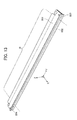
- FIG. 13 is a perspective view of the guide member
- FIG. 14 is an exploded perspective view of the support section illustrated in FIG. 2 ;
- FIG. 15 is a perspective view of the support section in an assembled state. Further, FIG. 16 is a perspective view of the support section in the assembled state when viewed from another angle;
- FIG. 17 is a cross-sectional view for describing a structure of supporting the device main unit by using the support section
- FIG. 18 is a graph that illustrates the burr heights of the paper sheet before and after the processing by the deburring device
- FIG. 19 is a graph that illustrates the amount of scratches produced on the belt of the fixing device in the image forming device
- FIG. 20 is a graph that illustrates the operating sound in each condition of the belt member
- FIG. 21 is a graph that illustrates the ratio between the vibration in the frame of the deburring device and the vibration in the support frame of the image forming device, in the image forming device of the example 1;
- FIG. 22 is a graph that illustrates the ratio between the vibration in the frame of the device main unit and the vibration in the support frame of the image forming device, in the comparative example.
- FIG. 1 is a schematic structural diagram that illustrates an embodiment of the image forming device according to the present invention.
- the image forming device 1 is a tandem type of color printer in which six image forming sections 10 A, 10 B, 10 C, 10 D, 10 E and 10 F that respectively form images of mutually different colors are disposed in parallel.
- the image forming device 1 is capable of printing a single-colored image in a single-color mode and a color image formed by toner images of plural colors in a full-color mode.
- the four image forming sections 10 C, 10 D, 10 E and 10 F correspond to yellow (Y), magenta (M), cyan (C) and black (K), respectively, and the remaining two image forming sections 10 A and 10 B correspond to spot colors except these YMCK colors.
- the spot colors include, for example, colors that are not easy to precisely express by the combination of YMCK, such as a color that represents a corporate color of a particular company, pastel colors, and transparent colors for luster.
- the image forming device 1 includes six toner cartridges 18 A, 18 B, 18 C, 18 D, 18 E and 18 F that contain toners of the colors corresponding to the image forming sections 10 A through 10 F, respectively.
- the image forming section 10 F includes a photoreceptor 11 , a charging device 12 that charges the surface of the photoreceptor 11 , an exposure device 13 that irradiates the photoreceptor 11 with exposure light based on an image signal supplied externally, a developing device 14 that develops the surface of the photoreceptor 11 with a toner, and a primary transfer device 15 that transfers the toner image to an intermediate transfer belt 20 .
- the photoreceptor 11 has a surface in the shape of a cylinder and rotates in the direction of an arrow “a” around an axis of the cylinder.
- the image forming device 1 includes the intermediate transfer belt 20 to which the toner image is transferred from the photoreceptor 11 of each of the image forming sections 10 A through 10 F, a secondary transfer device 30 that transfers the toner image from the intermediate transfer belt 20 to a paper sheet, a fixing device 40 that fixes the toner on the paper sheet, a decurler 50 that corrects a curl of the paper sheet, and a paper conveyance section 60 that conveys the paper sheet along a conveyance course 1 and a front-and-back inversion course R 2 .
- the image forming device 1 includes paper containers 71 and 72 that contain the paper sheet (s), a deburring device 80 that removes a burr of the paper sheet before image formation, a posture correcting section 73 that corrects the posture of the paper sheet.
- the image forming device 1 further includes a cooling device 74 that cools the paper sheet after the toner image is fixed, an output paper container 69 that receives the paper sheet after the image formation by the image forming device 1 is completed, and a controller 90 that controls each section of the image forming device 1 .
- the intermediate transfer belt 20 is a belt-shaped endless member supported by belt support rolls 21 , 22 and 23 , and circulates in the direction of an arrow “b” that passes by the image forming sections 10 A through 10 F and the secondary transfer device 30 in this order.
- the combination of the image forming sections 10 A through 10 F, the intermediate transfer belt 20 , the secondary transfer device 30 and the fixing device 40 is an example of the image forming section according to the present invention.
- the paper conveyance section 60 conveys the paper sheet along the conveyance course R 1 and the front-and-back inversion course R 2 .
- the paper conveyance section 60 includes drawing rolls 61 and 62 that draw paper sheets from the paper containers 71 and 72 , respectively, a registration roll 64 that sends each of the paper sheets to the secondary transfer device 30 in timing for the transfer of the toner image by the secondary transfer device 30 , belt conveyance devices 65 that convey the paper sheet from the secondary transfer device 30 to the fixing device 40 while making the paper sheet cling to the outer surfaces of the belt conveyance devices 65 , an output roll 66 that outputs the paper sheet to the outside of the image forming device 1 , and conveyance rolls 68 that are respectively disposed along the conveyance course R 1 and the front-and-back inversion course R 2 and convey the paper sheets.
- FIG. 1 only a part of the conveyance rolls 68 in the image forming device 1 is indicated by a reference character for easy viewing.
- the paper conveyance section 60 conveys the paper sheet from each of the paper containers 71 and 72 along the conveyance course R 1 passing through the deburring device 80 , the posture correcting section 73 , the secondary transfer device 30 , the fixing device 40 , the cooling device 74 and the decurler 50 sequentially.
- the paper conveyance section 60 conveys the paper sheet along the front-and-back inversion course R 2 diverging from the conveyance course R 1 and returning to the conveyance course R 1 . Subsequently, the paper sheet is turned back and then turned upside down in the front-and-back inversion course R 2 .
- the paper sheet after being turned upside down returns to the conveyance course R 1 , subsequently passes through the deburring device 80 and the posture correcting section 73 again, and the toner image is transferred by the secondary transfer device 30 to the reverse side of the paper sheet, namely the side to which the toner image is yet to be transferred.
- the developing device 14 forms a toner image by developing the electrostatic latent image with a black toner.
- the developing device 14 of the image forming section 10 F is supplied with the toner by the toner cartridge 18 F.
- the photoreceptor 11 retains the toner image upon formation of the toner image.
- the toner image formed on the surface of the photoreceptor 11 is transferred to the intermediate transfer belt 20 by the primary transfer device 15 .
- the paper sheets in the paper containers 71 and 72 are taken out by the drawing rolls 61 and 62 , and then conveyed along the conveyance course R 1 in the direction of an arrow “c” by the conveyance roll 68 and the registration roll 64 toward the secondary transfer device 300 .
- the burr removing device 80 disposed in the conveyance course R 1 removes a burr present at an edge of the paper sheet, and the posture and the position of the paper sheet are corrected by the posture correcting section 73 .
- the secondary transfer device 30 transfers the toner images on the intermediate transfer belt 20 to the paper sheet, by applying a bias potential for transfer between the intermediate transfer belt 20 and the paper sheet. The toner images are finally transferred to the paper sheet by the secondary transfer device 30 in this way.
- the paper sheet is then further conveyed in the direction of an arrow “d” by the belt conveyance devices 65 , and the toner images transferred to the surface of the paper sheet are fixed by the fixing device 40 .
- the fixing device 40 has a fixing belt 410 to raise thermal capacity.
- the paper sheet with the surface where the image is formed is cooled by the cooling device 74 , and then a curl of the paper sheet is corrected by the decurler 50 . Subsequently, the paper sheet is output by the output roll 66 .
- the paper conveyance section 60 conveys, along the front-and-back inversion course R 2 , a paper sheet after being conveyed along the conveyance course R 1 .
- the paper conveyance section 60 turns the paper sheet upside down and then conveys the paper sheet along the conveyance course R 1 again.
- the paper conveyance section 60 temporarily retracts, up to a midpoint of the front-and-back inversion course R 2 , the paper sheet after being conveyed along the conveyance course R 1 .
- the paper conveyance section 60 conveys the paper sheet in the reverse direction and then outputs the paper sheet.
- the output paper sheet is then laid in the output paper container 69 .
- FIG. 2 is a perspective diagram of the deburring device that is an exemplary embodiment of the medium clamping device according to the present invention.
- the deburring device 80 illustrated in FIG. 2 is disposed below the image forming sections 10 A, 10 B, 10 C, 10 D, 10 E and 10 F and the secondary transfer device 30 in the image forming device 1 illustrated in FIG. 1 .
- the deburring device 80 is attached to a support frame F (see FIG. 1 ) that supports the entire structure of the image forming device 1 .
- the deburring device 80 includes a device main unit 80 A and a support section 80 B that supports the device main unit 80 A.
- the deburring device 80 further includes a motor unit 800 (see FIG. 16 ) that will be described later.
- the support section 80 B is attached to the support frame F of the image forming device 1 and supports the device main unit 80 A while allowing the device main unit 80 A to be removable from the image forming device 1 .
- a direction in which the device main unit 80 A conveys a paper sheet is referred to as a conveyance direction X (or, a passing direction X).
- a direction that extends along the width of the conveyed paper sheet and crosses the conveyance direction X is referred to as a widthwise direction Y.
- a direction that crosses the conveyance direction X and the widthwise direction Y is referred to as a vertical direction Z.
- FIG. 3 is a perspective diagram that illustrates a state in which the device main unit of the deburring device illustrated in FIG. 2 is being drawn from the support section.
- the support section 80 B is provided with rails 891 extending in the widthwise direction Y, and rails 811 extending in parallel with the rails 891 in the widthwise direction Y are provided at an upper part of the device main unit 80 A.
- the rails 891 of the support section 80 B are formed by bending both edges of the support section 80 B outwardly along the conveyance direction X. Hence, there are two rails 891 provided at both sides of the support section 80 B aligned along the conveyance direction X.
- the rails 811 of the device main unit 80 A are formed by bending inwardly upper parts at both sides of a frame 81 , which supports the entire structure of the device main unit 80 A, namely, by bending these upper parts in the direction of facing each other.
- the rails 811 of the device main unit 80 A are provided to correspond to the rails 891 of the support section 80 B.
- the rails 811 of the device main unit 80 A are on the rails 891 of the support section 80 B.
- the rails 811 of the device main unit 80 A move while sliding on the rails 891 , so that the device main unit 80 A moves in the widthwise direction Y along which the rails 891 extend.
- an operator pulls the device main unit 80 A in the widthwise direction Y so that the device main unit 80 A is removed from the image forming device 1 .
- the device main unit 80 A is attached to the image forming device 1 by being pushed in along the widthwise direction Y.
- the frame 81 that supports the structure of the device main unit BOA is provided with projections 812 that position the device main unit 80 A relative to the support section 80 B when the device main unit 80 A is attached.
- the support section 80 B supports the device main unit 80 A via a buffering mechanism incorporated therein, but the structure of the support section 802 will be described later and the device main body 80 A will be described first.
- FIG. 4 is a perspective view of the device main unit illustrated in FIG. 3 .
- FIG. 5 is a sectional view that illustrates a schematic structure of the inside of the device main unit illustrated in FIG. 4 .
- the device main unit 80 A allows the supplied paper sheet to pass between the auxiliary conveyance rolls 83 A and 83 B, while causing the paper guide section 84 to guide the supplied paper sheet.
- the device main unit BOA allows the paper sheet to pass between the deburring rolls 82 A and 82 B and then causes the paper guide section 85 to guide the paper sheet which is then output.
- the pair of deburring rolls 82 A and 82 B are disposed at positions to vertically sandwich the paper sheet and to face each other.
- the deburring rolls 82 A and 82 B function as a first circularly moving body (in other words, a first cylindrical body) and a second circularly moving body (in other words, a second cylindrical body), respectively, each having a circumferential surface that moves circularly.
- the (lower) deburring roll 82 B disposed at a lower position is a drive roll that is driven to rotate by a deburring driving motor 801 (see FIG. 16 ).
- the (upper) deburring roll 82 A is disposed at an upper position and serves as a following roll.
- FIG. 4 illustrates a grip 821 that enables the operator to rotate the lower deburring roll 82 B manually so that a paper sheet is removed when a paper jam occurs.
- the pair of auxiliary conveyance rolls 83 A and the pair of auxiliary conveyance rolls 83 B are members that rotate while holding the paper sheet in between thereby conveying the paper sheet. Even in a state in which the deburring rolls 82 A and 82 B are away from each other, which will be described later, the paper sheet is conveyed by the auxiliary conveyance rolls 83 A and 83 B.
- the (lower) auxiliary conveyance rolls 83 B disposed at a lower position are drive rolls, whereas the (upper) auxiliary conveyance rolls 83 A disposed to face the lower auxiliary conveyance roll 83 B are following rolls.
- the lower auxiliary conveyance rolls 83 B are driven by the deburring driving motor 801 (see FIG. 16 ) through a gear (not illustrated) linked to the lower deburring roll 82 B.
- the upper deburring roll 82 A is given a load directed to the lower deburring roll 82 B, so that when the paper sheet is clamped between the upper deburring roll 82 A and the lower deburring roll 82 B, the height of a burr present at an edge of the paper sheet is reduced.
- a burr B swelling due to the cutting is formed at the edge of the paper sheet P.
- the burr B is usually formed at the edge of each of four sides of the paper sheet.
- the burr hits the intermediate transfer belt 20 and/or the fixing belt 410 of the fixing device 40 , causing scratches that lead to an image defect.
- the burr B of the paper sheet is pressed and a burr height H is reduced. Further, the crest of the burr B is deformed and smoothed.
- the paper sheet after passing between the upper deburring roll 82 A and the lower deburring roll 82 B in the deburring device 80 is supplied to the secondary transfer device 30 and the fixing device 40 and the image is formed. Since the paper sheet after the burr B is smoothed and the burr height H is reduced is applied to the secondary transfer device 30 and the fixing device 40 disposed downstream from the deburring device 80 , occurrences of scratches and image defects due to the scratches are reduced.
- FIG. 7 is a perspective view of the device main unit illustrated in FIG. 4 , when viewed from another angle. Further, FIG. 8 is a diagram for describing the structure of the roll support system.
- the roll support system 86 includes a roll support arm 861 that supports a rotation shaft of the upper deburring roll 82 A, a spring member 862 that presses the roll support arm 861 , a bolt 863 that holds down the spring member 862 , a cam 864 that causes the roll support arm 861 to move up and down, and a retracting motor 865 (see FIG. 8 ) that drives and thereby rotates the cam 864 .
- the roll support arm 861 is supported by a rotation shaft 861 P fixed to the frame 81 , and is rotatable relative to the frame 81 about the rotation shaft 861 P.
- the upper deburring roll 82 A is supported by the roll support arm 861 .
- the distance between the pin 861 B receiving the load of the spring member 862 and the rotation shaft 861 P is longer than the distance between the upper deburring roll 82 A and the rotation shaft 861 P.
- the distance between the rotation shaft 861 P and the pin 861 B is about five times the distance between the rotation shaft 861 P and the upper deburring roll 82 A. For this reason, the upper deburring roll 82 A is given a heavy load by the leverage as compared with the load applied by the spring member 862 to press the roll support arm 861 .
- the size of the load is regulated based on the fastening by the bolt 863 , and a load of 55 kgw is applied between the upper deburring roll 82 A and the lower deburring roll 82 B.
- the spring member 862 gives the pin 861 B a lighter load corresponding to the distance from the rotation shaft 861 P than the load applied to the upper deburring roll 82 A. Specifically, about one-fifth of the load applied to the upper deburring roll 82 A is given to the pin 861 B.
- the roll support arm 861 , the spring member 862 , the bolt 863 and the pin 861 B function as a load applying section, where the paper sheet is clamped between the upper deburring roll 82 A and the lower deburring roll 82 B by using the load applied to the upper deburring roll 82 A.
- the load applying section there may be adopted a structure in which the lower deburring roll 82 B in stead of the upper deburring roll 82 A is given a load or a structure in which both of these rolls are given a load.
- the load applying section there may be adopted a structure in which a load is directly applied to the shaft of the roll by using a spring member or the like without using the roll support arm although the size of the spring member is increased.
- FIG. 8 is a diagram that illustrates a clamping state in which the paper sheet is clamped between the upper deburring roll 82 A and the lower deburring roll 82 B.
- the cam 864 is rotated starting from this clamping state, the upper deburring roll 82 A retracts from and is thereby away from the lower deburring roll 82 B. Subsequently, a mechanism to shift the state will be described.
- a cam follower 861 A is provided at an end of the roll support arm 861 opposite to the end where the rotation shaft 861 P is provided, and the cam 864 is in contact with the roll support arm 861 via the cam follower 861 A.
- the cam 864 is an eccentric cam and has a notch 864 B at the furthest position in a cam surface from a rotation shaft 864 A.
- the cam 864 is driven to rotate by the retracting motor 865 controlled by the controller 90 (see FIG. 1 ).
- the retracting motor 865 drives the cam 864 by driving a gear 866 (see FIG. 5 ) that shares the rotation shaft 864 A with the cam 864 .
- a blade member 867 having a semicircle shape and corresponding to the displacement of the cam 864 is attached to the rotation shaft 864 A of the cam 864 .
- the blade member 867 represents the rotating posture of the cam 864 by rotating while interlocking with the cam 864 .
- a sensor 868 detects the passage of the blade member 867 and transmits a signal representing a detection result to the controller 90 (see FIG. 1 ).
- the controller 90 causes the cam 864 to rotate based on the signal sent from the sensor 868 , thereby enabling the cam 864 to take a predetermined posture.
- FIG. 9 is a diagram for describing the retraction movement of the roll.
- the retracting motor 865 drives and thereby rotates the cam 864
- the cam 864 pushes up the roll support arm 861 by resisting the pressing-down load applied by the spring member 862 .
- the blade member 867 rotates while interlocking with the cam 864 .
- the controller 90 causes the retracting motor 865 to stop rotating the cam 864 .
- the cam 864 is rotated a half turn and thereby contacts the cam follower 861 A at the furthest position from the center of rotation as illustrated in FIG. 9 .
- the cam 864 When the cam follower 861 A is engaged in the notch 864 B formed at the furthest position from the center of rotation of the cam 864 , the cam 864 is in a stable state at this furthest position.
- the retracting motor 865 , the cam 864 and the roll support arm 861 function as a switching section that switches between a separated state in which the upper deburring roll 82 A and the lower deburring roll 82 B are separated from each other and the clamping state in which the upper deburring roll 82 A and the lower deburring roll 82 B clamp the recording medium.
- the roll support arm 861 is rotated upward about the rotation shaft 861 P while being pushed up, and the upper deburring roll 82 A is retracted from the lower deburring roll 82 B.
- the upper deburring roll 82 A and the lower deburring roll 82 B are away from each other, preventing the paper sheet from being clamped.
- the space between the upper deburring roll 82 A and the lower deburring roll 82 B is sufficiently larger than the maximum thickness of the paper sheet processable by the image forming device 1 and thus, the paper sheet is not conveyed.
- the paper sheet is conveyed by the auxiliary conveyance rolls 83 A and 83 B and passes between the upper deburring roll 82 A and the lower deburring roll 82 B.
- the retracting motor 865 further rotates the cam 864 a half turn based on the controller 90 upon shifting from the separated state illustrated in FIG. 9 , the cam 864 contacts the cam follower 861 A at the nearest position from the center of rotation.
- the upper deburring roll 82 A and the lower deburring roll 82 B enter the clamping state where the paper sheet is clamped in between (see FIG. 8 ).
- the cam 864 and the cam follower 861 A may be separated from each other.
- the shift between the clamping state illustrated in FIG. 8 and the separated state illustrated in FIG. 9 is controlled by the controller 90 (see FIG. 1 ).
- the controller 90 controls the movement of the retracting motor 865 by running a program stored in a memory (not illustrated) with a processor.
- the controller 90 acquires the type of the recording medium based on input operation of the operator or data supplied from the outside of the image forming device 1 , and also obtains a processing state of the recording medium in each element of the image forming device 1 , thereby determining either the clamping state or the separated state.
- the controller 90 controls the entire image forming device 1 , but the controller 90 may be provided independently as a controller dedicated to the deburring device 80 .
- the recording medium is a paper-sheet medium, and when the recording medium has a basis weight higher than a predetermined basis weight, the upper deburring roll 82 A and the lower deburring roll 82 B are in the separated state.
- the basis weight is equal to or higher than 157 gsm, the upper deburring roll 82 A and the lower deburring roll 82 B are in the clamping state, whereas when the basis weight is lower than 157 gsm, the upper deburring roll 82 A and the lower deburring roll 82 B are in the separated state.
- the basis weight of 157 gsm is equivalent to the thickness of about 150 ⁇ m of a general paper sheet.
- the paper sheet whose basis weight is less than 157 gsm is clamped by the upper deburring roll 82 A and the lower deburring roll 823 , a wrinkle may be formed.
- the paper sheet having a basis weight of less than 157 gsm is softer than the paper sheet having a basis weight equal to or more than 157 gsm and therefore is unlikely to mar the members disposed downstream from the deburring device 80 such as the intermediate transfer belt 20 and the fixing belt 410 (see FIG. 1 ). Accordingly, for the paper sheet whose basis weight is less than 157 gsm, the upper deburring roll 82 A and the lower deburring roll 82 B are in the separated state and the clamping is not carried out.
- a passing recording medium is made of paper and has a width less than 320 mm in the widthwise direction Y ( FIG. 2 ) or when the recording medium is a medium made of a resin material such as an OHP seat and a resin film, a wrinkle is unlikely to occur as compared to a paper sheet having a width equal to or more than 320 mm. Therefore, in this case, the upper deburring roll 82 A and the lower deburring roll 82 B in the deburring device 80 are in the clamping state, thereby reducing scratches on the members disposed downstream.
- the image forming device 1 illustrated in FIG. 1 when an image is formed on each of both sides of a paper sheet, the paper sheet where the image is formed on one of the front and back sides is conveyed along the front-and-back inversion course R 2 . Subsequently, after the paper sheet turned upside down passes through the deburring device 80 , the image is formed on the other side.
- the upper deburring roll 82 A and the lower deburring roll 82 B are put in the separated state regardless of the type of paper sheet.
- FIG. 10 is a diagram that illustrates the upper deburring roll and the lower deburring roll.
- FIG. 10 illustrates the upper deburring roll 82 A and the lower deburring roll 82 B in the postures disposed in the deburring device 80 , when viewed in the conveyance direction X. Further, FIG. 10 illustrates the deburring driving motor 801 and a gear 803 that drive the lower deburring roll 82 B in a state in which the device main unit 80 A (see FIG. 3 ) is attached to the support section 80 B.
- the upper deburring roll 82 A and the lower deburring roll 82 B include roll main sections 823 A and 823 B each having a circumferential surface to be in contact with the paper sheet, and the rotation shafts 824 A and 824 B, respectively.
- the rotation shafts 824 A and 824 B are fixed at both sides of the roll main section 823 A and at both sides of the roll main section 823 B, respectively, and supported by the bearings 822 A and 822 B (see FIG. 7 ), respectively.
- the respective circumferential surfaces of the roll main sections 823 A and 823 B move circularly as the roll main sections 823 A and 823 B rotate.
- Each of the roll main sections 823 A and 823 B is made of a metal material harder than the paper sheet and is a hollow cylinder having a diameter of 35 mm. Specifically, each of the roll main sections 823 A and 823 B is made of stainless steel and has a nitrided surface. To be more specific, the surface of each of the roll main sections 823 A and 823 B is softnitrized.
- Each of the roll main sections 823 A and 823 B has a longer length in a direction orthogonal to a rotating direction R of the circumferential surface, namely in the widthwise direction Y in the present exemplary embodiment, than the length in the widthwise direction Y of the paper sheet conveyed between the upper deburring roll 82 A and the lower deburring roll 823 .
- each of the roll main sections 823 A and 823 B is made hard by the nitriding. For this reason, the surfaces of the roll main sections 823 A and 823 B are hard to deform and thus apply a high pressure to the burr when clamping the paper sheet. Therefore, as compared to a case in which the surface is not nitrided, the burr height of the paper sheet is further reduced.
- the upper deburring roll 82 A is provided with a belt member 825 that is disposed on the circumferential surface of the roll main section 823 A and at a position outside an area D that touches the paper sheet.
- the belt member 825 surrounds the circumferential surface of the roll main section 823 A at each of both sides outside the area D that touches, when the paper sheet of the maximum size processable by the image forming device passes between the upper deburring roll 82 A and the lower deburring roll 823 , this paper sheet of the maximum size.
- FIG. 10 illustrates the thickness of the belt member 825 in an expanded view for the description of the belt member 825 .
- the belt member 825 is softer than the roll main section 823 A and also thinner than a paper sheet having a minimum thickness (150 ⁇ m) among the paper sheets targeted for the deburring by the deburring device 80 . To be more specific, the belt member 825 is thinner than the thickness (about 100 ⁇ m) of a plain paper sheet widely used as copy paper.
- the belt member 825 is a tape having ends and a single layer that surrounds the circumferential surface of the roll main section 823 A. Both ends of the belt member 825 are close to each other across a border that is not orthogonal to the rotating direction R. To be more specific, both ends of the belt member 825 extend at an angle of 45 degrees relative to the rotating direction R.
- the belt member 825 includes a base layer 8251 made of a resin material and an adhesive layer 8252 that adheres this base layer to the circumferential surface.
- the base layer 8251 is a polyimide tape having a thickness of 50 ⁇ m
- the adhesive layer 8252 is an adhesive having a thickness of 30 ⁇ m. Therefore, the thickness of the entire belt member 825 is 80 ⁇ m.
- the material of the base layer polyurethane or polycarbonate that are softer than the roll main section 823 A may be employed.
- the base layer made of polyimide provides lower movement sound and higher friction durability than those of other resin materials.
- the base layer made of polyimide have the thickness of 50 ⁇ m, peeling of the end due to hardness and elasticity of the base layer when being wound around the roll is prevented, as compared to a case where the thickness is made equal to or larger than 50 ⁇ m.
- the upper deburring roll 82 A After the tail of the paper sheet passes between the upper deburring roll 82 A and the lower deburring roll 82 B, the upper deburring roll 82 A returns toward the lower deburring roll 82 B due to the load applied by the spring member 862 (see FIG. 8 ). At this moment, a shock occurs due to collision, and if the respective hard circumferential surfaces of the roll main section 823 A and the roll main section 823 B hit each other, a large shock is produced, causing loud impulsive sound. Moreover, when the shock is transmitted to the image forming sections 10 A, 10 B, 10 C, 10 D, 10 E and 10 F as well as the secondary transfer device 30 of the image forming device, the image is disturbed.
- the roll main section 823 B of the lower deburring roll 82 B hits the belt member 825 of the roll main section 823 A of the upper deburring roll 82 A.
- a shock occurring here is absorbed by the belt member 825 that is softer than the upper deburring roll 82 A and the lower deburring roll 82 B.
- the belt member 825 is thinner than the paper sheet having the maximum thickness. Therefore, the paper sheet is clamped between the upper deburring roll 82 A and the lower deburring roll 82 B by the applied load regardless of the belt member 825 when the paper sheet passes therebetween and thus, the burr is corrected without a hitch.
- the upper deburring roll 82 A rotates while causing the belt member 825 to touch the roll main section 823 B of the lower deburring roll 82 B.
- both ends of the belt member 825 are close to each other across the border that is not orthogonal to the rotating direction R, the roll main section 823 B of the lower deburring roll 82 B smoothly rolls across the belt member 825 from one end to the other end of the belt member 825 . Therefore, vibrations accompanying the rotation of the lower deburring roll 82 B in the state of no recording medium are reduced as compared to a case in which these both ends are orthogonal to the rotating direction R.
- FIG. 12 is a plane view that illustrates the positions of the guide member, the deburring roll and the auxiliary conveyance rolls in the device main unit.
- FIG. 12 illustrates only the paper guide sections 84 and 85 , the upper deburring roll 82 A, and the upper auxiliary conveyance rolls 83 A.
- the paper guide sections 84 and 85 are disposed upstream and downstream from the upper deburring roll 82 A, respectively, in the conveyance direction X.
- the structures of the paper guide section 84 disposed upstream and the paper guide section 85 disposed downstream are the same except the length in the conveyance direction X.
- the paper guide section 84 includes a pair of flat members 841 and protruding members 843 and 844 interposed between the pair of flat members 841 .
- FIG. 13 is a perspective view of the guide member.
- FIG. 13 illustrates, of the two paper guide sections 84 and 85 , the paper guide section 85 disposed downstream in the conveyance direction X.
- the paper guide section 85 includes a pair of flat members 851 and 852 and protruding members 853 and 854 interposed between the flat members 851 and 852 .
- Each of the flat members 851 and 852 is in the shape of a plate expanding along the front and back surfaces of the paper sheet passing between the upper deburring roll 82 A and the lower deburring roll 82 B.
- a path D where the paper sheet is to pass is provided between the pair of flat members 851 and 852 that sandwich the path D in the vertical direction Z crossing the front and back surfaces of the paper sheet.
- the protruding members 853 and 854 are flat members that fill the space between the flat members 851 and 852 at both ends in the widthwise direction Y of the flat members 851 and 852 , thereby keeping the distance between the pair of flat members 851 and 852 uniform.
- the paper sheet is guided by the paper guide section 84 thereby passing between the pair of auxiliary conveyance rolls 83 A and the pair of auxiliary conveyance rolls 83 B and then, upon passing between the pair of deburring rolls 82 A and 82 B the paper sheet is guided by the paper guide section 85 and output.
- the pair of protruding members 843 and 844 provided in the paper guide section 84 are aligned with the pair of belt members 825 in the conveyance direction X in which the paper sheet passes, and disposed at positions protruding beyond the pair of belt members 825 relative to the path D.
- each of the protruding members 843 and 844 has a downstream end and an upstream end in the conveyance direction X, and the downstream end protrudes closer to the path D than the upstream end. For this reason, the position of the paper sheet entering while deviating from the path D is corrected toward the path D.
- FIG. 14 is an exploded perspective view of the support section illustrated in FIG. 2 .
- the support section 80 B has a fixed section 87 , buffer members 88 attached to the fixed section 87 , and a rail member 89 attached to the buffer members 88 .
- the fixed member 87 is fixed to the support frame F of the image forming device 1 .
- the fixed section 87 is fixed to the support frame F.
- Each of the buffer members 88 has a structure in which a pair of fixing plates 882 and 883 for screwing a buffer material 881 made of urethane resin are respectively adhered to the bottom and the top of the buffer material 881 .
- the buffer material 881 has a height of 15 mm.
- the reference characters 881 through 883 are provided for only one of the four buffer members 88 for easy viewing.
- FIG. 15 is a perspective view of the support section in an assembled state.
- FIG. 16 is a perspective view of the support section in the assembled state when viewed from another angle.
- FIG. 16 illustrates a state in which the deburring driving motor and the gear are attached to the support section illustrated in FIG. 15 .
- the support section 80 B illustrated in FIG. 16 is attached in the image forming device 1 by screwing the fixing pieces 871 and 872 of the fixed section 87 to the support frame F.
- the operator places the edges of the pair of rails 811 (see FIG. 4 ), which are provided at the upper part of the frame 81 of the device main unit 80 A, on the edges of the pair of rails 891 of the support section 803 , respectively. Afterwards, as illustrated in FIG. 3 , the device main unit 80 A is pushed in by the operator and thereby being attached.
- the gear 803 of the motor unit 80 C is connected to the lower deburring roll 82 B.
- the frame 81 of the device main unit 80 A is provided with the projections 812 ( FIG. 3 ) protruding in the widthwise direction Y.
- the projections 812 are respectively engaged in the positioning sections 892 provided in the rail member 89 so that the device main unit 80 A is positioned relative to the rail member 89 .
- the shock produced when the roll main sections 823 A and 823 B are in the clamping state is absorbed and thus reduced by the belt member 825 of the roll main section 823 A.
- a residual shock as not being absorbed and/or vibration due to the movements of the device main unit 80 A other than this shock are transmitted to the image forming sections 10 A, 10 B, 10 C, 10 D, 10 E and 10 F and the secondary transfer device 30 , the image is disturbed.
- the support section 803 alleviates the transmission of the shock and vibration by using the buffering mechanism incorporated therein. Incidentally, in the following description, the vibration will be included in the shock, unless otherwise specified.
- FIG. 17 is a cross-sectional view for describing a structure of supporting the device main unit by using the support section.
- the device main unit 80 A is positioned relative to the rail member 89 by the projections 812 (see FIG. 3 ) and the positioning sections 892 ( FIG. 16 ), and the motor unit 80 C also is fixed to the support section 80 B.
- An image forming device of an example based on the exemplary embodiment is made, and characteristics are measured.
- a paper sheet is passed in the deburring device, and the burr height H ( FIG. 6 ) of a burr of the paper sheet before passing and that after passing are measured.
- FIG. 18 is a graph that illustrates the burr heights of the paper sheet before and after the processing by the deburring device.
- the burr height after the deburring processing is reduced as compared to the burr height before the deburring processing.
- the amount of scratches produced on the fixing belt 410 of the fixing device 40 (see FIG. 1 ) disposed downstream from the deburring device is checked for a case in which the deburring processing is performed by the deburring device and a case in which the deburring processing is not performed.
- the amount of scratches produced on the belt is evaluated by viewing from 0 (no scratch is found) to 5 grades in steps of 0.5.
- FIG. 19 is a graph that illustrates the amount of scratches produced on the belt of the fixing device in the image forming device.
- a horizontal axis of the graph indicates the number of paper sheets processed by the image forming device, and the unit of the numbers is 1,000 sheets (kPV).
- the grade expressing the amount of scratches produced on the belt of the fixing device at a stage where 5,000 sheets are processed is increased to 2
- the grade at a stage where 10,000 sheets are processed is increased to 4.
- the grade does not reach 2 even at a stage where 40,000 sheets are processed.
- the belt member in the example 1 includes a base layer made of polyimide and having a thickness of 50 ⁇ m and an adhesive layer having a thickness of 30 ⁇ m.
- an example 2 is made by employing a base layer having the same thickness as that in the example 1 and made of another material, namely polyurethane.
- an example 3 is made by employing a base layer made of polyimide and having a thickness of 70 ⁇ m.
- an example 4 is made by employing a base layer having the same thickness as that in the example 3 and made of polycarbonate.
- the adhesive layer is made to have a thickness of 10 ⁇ m.
- a comparative example having no belt member (tape) is prepared. These examples 1 through 4 and the comparative example are operated, and the steady sound is measured.
- FIG. 20 is a graph that illustrates the operating sound in each condition of the belt member.
- the level of the steady sound is reduced in each of the examples 1 through 4 each having the belt member.
- durability of the belt member in each of the examples 1 through 4 is examined.
- adhesive strength and abrasion resistance of the belt member are measured.
- the adhesive strength in each of the examples 1 through 4 is measured as follows. After the belt member is adhered to the upper deburring roll, the belt member is left alone for 24 hours and then the adhesive strength at the time when the belt member is peeled by a 90 degrees peeling method is measured. The results obtained by measuring the adhesive strength are as follows.
- Example 1 (polyimide 50 ⁇ m): 300 gw
- Example 2 (polyurethane 50 ⁇ m): 330 gw
- Example 3 (polyimide 70 ⁇ m): 100 gw
- Example 4 (polycarbonate 70 ⁇ m): 150 gw
- a load test is run on the friction. Specifically, in the deburring device 80 in each of the examples 1 through 4, the upper deburring roll provided with the belt member is prevented from rotating and given a load of 55 kgw. In this state, when the lower deburring roll is driven to rotate, the lower deburring roll rotates while rubbing against a single spot of the belt member.
- the base material of the belt member in the example 2 (polyurethane 50 ⁇ m) is damaged after 60 minutes and the base material of the belt member in the example 4 (polycarbonate 70 ⁇ m) is damaged after 50 minutes, each following the start of the rotation of the lower deburring roll.
- the example 1 (polyimide 50 ⁇ m) and the example 3 (polyimide 70 ⁇ m) no damage is found even after a lapse of 12 hours following the start of the rotation of the lower deburring roll.
- a sensor that detects vibration is attached to each of the frame 81 (see FIG. 4 ) of the deburring device and the support frame F (see FIG. 16 ) of the image forming device 1 , and then a shock is applied to the frame 81 of the deburring device. Subsequently, a ratio between the amplitude of the vibration due to the shock detected by one of the sensors and that of the other sensor is measured as a gain of a transmission function. Also, the ratio between the vibrations is measured in a comparative example in which the rail member 89 is directly fixed to the fixed section 87 without using the buffer members 88 .
- FIG. 21 is a graph that illustrates the ratio between the vibration in the frame of the deburring device and the vibration in the support frame of the image forming device, in the image forming device of the example 1.
- FIG. 22 is a graph that illustrates the ratio between the vibration in the frame of the device main unit and the vibration in the support frame of the image forming device, in the comparative example.
- a horizontal axis of the graph in each of FIG. 21 and FIG. 22 indicates the frequency (component) of the vibration
- a vertical axis indicates the ratio (gain) of the vibration in the support frame of the image forming device to the vibration in the frame of the device main unit.
- the ratio (gain) of the vibration in the image forming device of the example 1 illustrated in the graph of FIG. 21 is reduced to be less than the ratio of the vibration in the comparative example illustrated in the graph of FIG. 22 , in any of the frequencies in the graph. Further, the ratio of the vibration in the example 1 is smaller than 1 in any of the frequencies in the graph. It is found that the transmission of the shock from the main unit of the deburring device to the support frame of the image forming device is alleviated by providing the buffer members 88 .
- tandem type of color printer is described as an example of the image forming device, but the image forming device is not limited to this example and may be, for example, a printer dedicated to monochrome and having no intermediate transfer belt.
- the printer is described as an example of the image forming device, but the image forming device is not limited to this example and may be, for example, a copier or a facsimile.
- the combination of the charging device, the exposure device and the developing device is described as an example of the image forming section, but the image forming section is not limited to this example and may be, for example, an element that causes a toner to directly adhere to a position corresponding to an image on an image retainer by aiming that position.
Landscapes
- Physics & Mathematics (AREA)
- General Physics & Mathematics (AREA)
- Delivering By Means Of Belts And Rollers (AREA)
- Separation, Sorting, Adjustment, Or Bending Of Sheets To Be Conveyed (AREA)
- Feeding Of Articles By Means Other Than Belts Or Rollers (AREA)
- Paper Feeding For Electrophotography (AREA)
Abstract
Description
Claims (19)
Applications Claiming Priority (2)
| Application Number | Priority Date | Filing Date | Title |
|---|---|---|---|
| JP2009280535A JP5402597B2 (en) | 2009-12-10 | 2009-12-10 | Medium clamping apparatus and image forming apparatus |
| JP2009-280535 | 2009-12-10 |
Publications (2)
| Publication Number | Publication Date |
|---|---|
| US20110142514A1 US20110142514A1 (en) | 2011-06-16 |
| US8428504B2 true US8428504B2 (en) | 2013-04-23 |
Family
ID=44143077
Family Applications (1)
| Application Number | Title | Priority Date | Filing Date |
|---|---|---|---|
| US12/851,914 Expired - Fee Related US8428504B2 (en) | 2009-12-10 | 2010-08-06 | Medium clamping device and image forming device |
Country Status (2)
| Country | Link |
|---|---|
| US (1) | US8428504B2 (en) |
| JP (1) | JP5402597B2 (en) |
Families Citing this family (4)
| Publication number | Priority date | Publication date | Assignee | Title |
|---|---|---|---|---|
| JP5769543B2 (en) * | 2011-08-18 | 2015-08-26 | キヤノン株式会社 | Sheet compression apparatus and image forming apparatus |
| JP5832198B2 (en) * | 2011-08-19 | 2015-12-16 | キヤノン株式会社 | Sheet compression apparatus and image forming apparatus |
| JP2016197145A (en) * | 2015-04-02 | 2016-11-24 | 株式会社東芝 | Image processor and image display device |
| JP7655008B2 (en) * | 2021-03-04 | 2025-04-02 | セイコーエプソン株式会社 | Media loading device and image forming system |
Citations (5)
| Publication number | Priority date | Publication date | Assignee | Title |
|---|---|---|---|---|
| JPS5833279A (en) * | 1981-08-13 | 1983-02-26 | Copyer Co Ltd | Pressure fixing device of copying machine |
| JPH01303249A (en) * | 1988-05-31 | 1989-12-07 | Minolta Camera Co Ltd | Width regulation mechanism of media |
| JPH10218459A (en) * | 1997-01-30 | 1998-08-18 | Ricoh Co Ltd | Image forming device |
| US6082731A (en) * | 1998-03-19 | 2000-07-04 | Fujitsu Limited | Medium processing apparatus and a medium positioning mechanism |
| JP2008254887A (en) | 2007-04-05 | 2008-10-23 | Fuji Xerox Co Ltd | Recording material correction device and image forming device |
Family Cites Families (4)
| Publication number | Priority date | Publication date | Assignee | Title |
|---|---|---|---|---|
| JPS53159335U (en) * | 1977-05-20 | 1978-12-13 | ||
| JPS58148137A (en) * | 1982-02-25 | 1983-09-03 | Canon Inc | Sheet conveyance device with sheet alignment mechanism |
| JPH0683238A (en) * | 1992-08-28 | 1994-03-25 | Fuji Xerox Co Ltd | Pressure fixing device |
| JPH07179243A (en) * | 1993-12-22 | 1995-07-18 | Nippon Signal Co Ltd:The | Medium carrying passage |
-
2009
- 2009-12-10 JP JP2009280535A patent/JP5402597B2/en not_active Expired - Fee Related
-
2010
- 2010-08-06 US US12/851,914 patent/US8428504B2/en not_active Expired - Fee Related
Patent Citations (5)
| Publication number | Priority date | Publication date | Assignee | Title |
|---|---|---|---|---|
| JPS5833279A (en) * | 1981-08-13 | 1983-02-26 | Copyer Co Ltd | Pressure fixing device of copying machine |
| JPH01303249A (en) * | 1988-05-31 | 1989-12-07 | Minolta Camera Co Ltd | Width regulation mechanism of media |
| JPH10218459A (en) * | 1997-01-30 | 1998-08-18 | Ricoh Co Ltd | Image forming device |
| US6082731A (en) * | 1998-03-19 | 2000-07-04 | Fujitsu Limited | Medium processing apparatus and a medium positioning mechanism |
| JP2008254887A (en) | 2007-04-05 | 2008-10-23 | Fuji Xerox Co Ltd | Recording material correction device and image forming device |
Also Published As
| Publication number | Publication date |
|---|---|
| US20110142514A1 (en) | 2011-06-16 |
| JP2011121703A (en) | 2011-06-23 |
| JP5402597B2 (en) | 2014-01-29 |
Similar Documents
| Publication | Publication Date | Title |
|---|---|---|
| US9335668B2 (en) | Transfer device and image forming apparatus including same | |
| JP2009234743A (en) | Sheet conveying apparatus and image forming apparatus | |
| EP2028552A2 (en) | Recording medium deburring apparatus and image forming apparatus | |
| JP2007334292A (en) | Image forming apparatus | |
| US8428504B2 (en) | Medium clamping device and image forming device | |
| JP2009161301A (en) | Sheet conveying apparatus and image forming apparatus | |
| JP5472782B2 (en) | Image forming apparatus | |
| AU2009202277B2 (en) | Recording material processing apparatus | |
| US8606167B2 (en) | Medium clamping device and image forming device | |
| JP6643012B2 (en) | Belt transport device and image forming device | |
| JP2011157189A (en) | Sheet discharging device and image forming device | |
| US20120034008A1 (en) | Separating device and image forming apparatus | |
| EP2397912B1 (en) | Image forming apparatus | |
| CN104925550B (en) | Sheet feeder and image forming apparatus | |
| JP5515705B2 (en) | Medium clamping apparatus and image forming apparatus | |
| US8292297B2 (en) | Sheet separation mechanism and image forming apparatus with first and second biasing members | |
| JP2011121702A (en) | Medium clamping device and image forming device | |
| JP5560684B2 (en) | Medium clamping apparatus and image forming apparatus | |
| JP4966103B2 (en) | Image forming apparatus | |
| JP4884913B2 (en) | Image forming apparatus | |
| JP4840863B2 (en) | Transfer material conveying apparatus and image forming apparatus | |
| JP2023145855A (en) | Media transport device and image forming device | |
| JP2010155681A (en) | Sheet ejecting device and image forming device | |
| US7359668B2 (en) | Image fixing device | |
| JP2008265950A (en) | Image forming apparatus |
Legal Events
| Date | Code | Title | Description |
|---|---|---|---|
| AS | Assignment |
Owner name: FUJI XEROX CO., LTD., JAPAN Free format text: ASSIGNMENT OF ASSIGNORS INTEREST;ASSIGNORS:ANDO, CHIKARA;SASAKI, TOSHINORI;FUNAYANAGI, MASARU;REEL/FRAME:024806/0654 Effective date: 20100628 |
|
| FEPP | Fee payment procedure |
Free format text: PAYOR NUMBER ASSIGNED (ORIGINAL EVENT CODE: ASPN); ENTITY STATUS OF PATENT OWNER: LARGE ENTITY |
|
| STCF | Information on status: patent grant |
Free format text: PATENTED CASE |
|
| FPAY | Fee payment |
Year of fee payment: 4 |
|
| MAFP | Maintenance fee payment |
Free format text: PAYMENT OF MAINTENANCE FEE, 8TH YEAR, LARGE ENTITY (ORIGINAL EVENT CODE: M1552); ENTITY STATUS OF PATENT OWNER: LARGE ENTITY Year of fee payment: 8 |
|
| AS | Assignment |
Owner name: FUJIFILM BUSINESS INNOVATION CORP., JAPAN Free format text: CHANGE OF NAME;ASSIGNOR:FUJI XEROX CO., LTD.;REEL/FRAME:058287/0056 Effective date: 20210401 |
|
| FEPP | Fee payment procedure |
Free format text: MAINTENANCE FEE REMINDER MAILED (ORIGINAL EVENT CODE: REM.); ENTITY STATUS OF PATENT OWNER: LARGE ENTITY |
|
| LAPS | Lapse for failure to pay maintenance fees |
Free format text: PATENT EXPIRED FOR FAILURE TO PAY MAINTENANCE FEES (ORIGINAL EVENT CODE: EXP.); ENTITY STATUS OF PATENT OWNER: LARGE ENTITY |
|
| STCH | Information on status: patent discontinuation |
Free format text: PATENT EXPIRED DUE TO NONPAYMENT OF MAINTENANCE FEES UNDER 37 CFR 1.362 |
|
| FP | Lapsed due to failure to pay maintenance fee |
Effective date: 20250423 |