US8427166B2 - State of health recognition of secondary batteries - Google Patents
State of health recognition of secondary batteries Download PDFInfo
- Publication number
- US8427166B2 US8427166B2 US12/581,773 US58177309A US8427166B2 US 8427166 B2 US8427166 B2 US 8427166B2 US 58177309 A US58177309 A US 58177309A US 8427166 B2 US8427166 B2 US 8427166B2
- Authority
- US
- United States
- Prior art keywords
- battery
- state
- charge
- double layer
- electrical double
- Prior art date
- Legal status (The legal status is an assumption and is not a legal conclusion. Google has not performed a legal analysis and makes no representation as to the accuracy of the status listed.)
- Expired - Fee Related, expires
Links
Images


Classifications
-
- G—PHYSICS
- G01—MEASURING; TESTING
- G01R—MEASURING ELECTRIC VARIABLES; MEASURING MAGNETIC VARIABLES
- G01R31/00—Arrangements for testing electric properties; Arrangements for locating electric faults; Arrangements for electrical testing characterised by what is being tested not provided for elsewhere
- G01R31/36—Arrangements for testing, measuring or monitoring the electrical condition of accumulators or electric batteries, e.g. capacity or state of charge [SoC]
- G01R31/392—Determining battery ageing or deterioration, e.g. state of health
-
- G—PHYSICS
- G01—MEASURING; TESTING
- G01R—MEASURING ELECTRIC VARIABLES; MEASURING MAGNETIC VARIABLES
- G01R31/00—Arrangements for testing electric properties; Arrangements for locating electric faults; Arrangements for electrical testing characterised by what is being tested not provided for elsewhere
- G01R31/36—Arrangements for testing, measuring or monitoring the electrical condition of accumulators or electric batteries, e.g. capacity or state of charge [SoC]
- G01R31/389—Measuring internal impedance, internal conductance or related variables
Definitions
- This invention relates generally to battery monitoring systems and, more particularly, to real-time battery State of Health detection utilizing a Matrix of battery Parameters.
- State of health recognition for a rechargeable battery is an important element of the total battery management in order to ensure proper operation of electrical systems operated by the battery.
- State of health can be considered as current state of charge, useful remaining life as a function of life cycle, and useful remaining discharge time as a function of the current discharge rate.
- Prior art techniques for discovering battery state of health generally only analyze current and voltage behavior by examining a battery utilizing an electronics approach. That is, prior art approaches examine the battery as though the battery were a transistor, and use a transistor analysis to categorize the battery.
- U.S. Pat. No. 6,956,355 describes a self-diagnosis system for an energy storage device, the latter including a plurality of electrochemical cells connected in series or parallel to form a cell string.
- the self-diagnosis system correlates a state of health of the battery based on the internal resistance value of each electrochemical cell of the energy storage device and determines a corresponding battery initial capacity which enables the self-diagnosis system to evaluate the exact capacity of the battery at any given time.
- batteries operate under much more complicated physical conditions than electronic devices.
- physical conditions for batteries include simultaneously charge, mass and heat unstationary transfer in three phase environments, which are much more complicated than the operating condition of single solid state electronic devices.
- systems and methods for real-time battery State of Health detection should examine intrinsic battery parameters to determine the battery's state of health.
- embodiments of the present invention examine significant chemical and physical parameters of a battery to determine the battery's state of health.
- a method for determining a state of health of a battery is disclosed. The method includes applying a predefined load profile to a battery and obtaining a plurality of battery response voltage data corresponding to points along the predefined load profile.
- a matrix of parameters which includes, among other data, battery ohm resistance data, battery chemical resistance data, and battery electrical double layer capacity data, is calculated from the battery response voltage data. Thereafter, the matrix of parameters is utilized to determine the state of health of the battery.
- the state of health of the battery generally state of charge of the battery, battery useful remaining life as a function of life cycle, and battery useful remaining discharge time as a function of current discharge rate.
- An additional method for determining a state of health of a battery includes generating a state of charge profile for a battery that indicates matrix of parameter data values corresponding to a plurality of battery state of charge percentages.
- the method continues by calculating a current matrix of parameters for the battery from the current battery response voltage data.
- the current matrix of parameters includes, among other data, battery ohm resistance data, battery chemical resistance data, and battery electrical double layer capacity data.
- the current matrix of parameters is compared to the state of charge profile to determine the current battery state of charge of the battery. The total state of health of the battery can then be determined based on the current battery state of charge.
- the useful remaining discharge time as a function of current discharge rate can be determined utilizing the current battery state of charge.
- the useful remaining life of the battery as a function of life cycle can be determined utilizing the current matrix of parameters. That is, as will be described in greater detail subsequently, an end to the useful remaining life of the battery can be predicted when a sharp rise occurs in the battery chemical resistance while the battery state of charge is about 0%, and/or when a sharp rise occurs in the electrical double layer capacity of a lead-acid battery while the battery state of charge is about 100%.
- the useful remaining life of a Li-ion battery can be predicted using the electrical double layer capacity value, which has a trend to decrease as per passed cycles number, regardless of Li-ion battery state of charge.
- a system for determining a state of health of a battery includes a switching circuit, which is coupled to a power source and a battery load.
- the switching circuit is capable of applying a predefined load profile to a battery.
- Coupled to the switching circuit is a battery management module.
- the battery management module includes logic that obtains a plurality of battery response voltage data corresponding to points along the predefined load profile.
- the battery management module also includes logic that calculates a matrix of parameters from the battery response voltage data.
- the matrix of parameters includes battery ohm resistance data, battery chemical resistance data, and battery electrical double layer capacity data, among other data.
- the battery management module includes logic that determines from the matrix of parameters the state of health of the battery.
- the battery management module can further include logic that generates a state of charge profile for the battery which indicates matrix of parameter data values corresponding to a plurality of battery state of charge percentages.
- logic can be included that compares the matrix of parameters to the state of charge profile to determine the current battery state of charge.
- the battery management module can determine the useful remaining discharge time as a function of current discharge rate.
- the battery management module can be configured to determine useful remaining life of the battery as a function of life cycle utilizing the matrix of parameters.
- the battery management module can predict imminent battery failure.
- the battery management module also can predict the remaining life a Li-ion battery by monitoring the electrical double layer capacity value, regardless of the battery state of charge.
- FIG. 1 is a block diagram of a battery charging and discharging circuit capable of battery state of health recognition in accordance with an embodiment of the present invention
- FIG. 2 is flowchart showing a method for performing battery diagnostic operations to determine the battery's state of health
- FIG. 3 is a flowchart showing method for determining a state of health of a battery in accordance with an embodiment of the present invention
- FIG. 4 is an illustration of an exemplary predefined load profile utilized during charging mode parameter acquisition, in accordance with an embodiment of the present invention
- FIG. 5 is an illustration of an exemplary predefined load profile utilized during diagnostic mode parameter acquisition, in accordance with an embodiment of the present invention
- FIG. 6 illustrates typical charge data taken over eighteen hundred sequences for a few of the channels of the charge mode predefined load profile of FIG. 5 ;
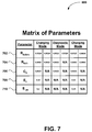
- FIG. 7 is a matrix of parameters table, in accordance with an embodiment of the present invention.
- FIG. 8 is a graph showing a state of charge profile for lead acid (LA) batteries
- FIG. 9 is a graph showing a state of charge profile for nickel metal hydride (NiMH) batteries.
- FIG. 10 is a graph showing a state of charge profile for nickel cadmium (NiCd) batteries
- FIG. 11 is a graph showing a state of charge profile for Li-ion batteries
- FIG. 12A is a graph showing the change in battery specific electrical double layer capacity, battery specific ohm resistance, and battery specific chemical resistance as a function of the cycle when the battery state of charge is about 0%;
- FIG. 12B is a graph showing the change in lead-acid battery specific electrical double layer capacity, battery specific ohm resistance, and battery specific chemical resistance as a function of the cycle when the battery state of charge is about 100%;
- FIG. 13 is a graph showing the change in Li-metaloxide and Li-nanophosphate Li-ion battery specific electrical double layer capacity as a function of cycles under any level of state of charge.
- Embodiments of the present invention examine multiply battery parameters to determine the battery's state of health. Through utilization of a matrix of parameters, embodiments of the present invention are capable of accurately portraying a battery condition. As a result, embodiments of the present invention can accurately determine a battery's state of health, which comprises state of charge, useful remaining battery life as a function of battery life cycle, and useful remaining battery discharge time as a function of the current battery discharge rate, regardless of the current discharging or cycling mode the battery is in.
- embodiments of the present invention can be utilized during charging of a battery, during separate analysis of the battery, or during any other time battery state of health information is needed.
- embodiments of the present invention apply a predefined load profile to a battery and obtain battery response voltage data that corresponds to points along the predefined load profile.
- the battery response voltage data is utilized thereafter to calculate a matrix of parameters, which includes battery data on the most significant battery chemical and physical parameters, such as the battery ohm resistance, chemical resistance, and electrical double layer capacity. From the matrix of parameters, embodiments of the present invention determine the state of health of the battery, including the battery state of charge, useful remaining battery life as a function of battery life cycle, and useful remaining battery discharge time as a function of the current battery discharge rate.
- embodiments of the present invention can be utilized during storage, charging or discharging of a battery, during separate analysis of the battery, or during any other time battery state of health information is needed.
- embodiments of the present invention will now be described as utilized during the process of charging a battery.
- the embodiments of the present invention are not limited to battery charging, and can be utilized any time battery state of health information is needed as described above.
- FIG. 1 is a block diagram of a battery charging and discharging circuit 100 capable of battery state of health recognition in accordance with an embodiment of the present invention.
- the battery charging and discharging circuit 100 of the embodiments of the present invention comprises a power source 102 , a variable or fixed battery load 104 , a switching circuit 105 , and a dynamic programmed logic battery management module 106 having timing and control with a Program Interrupt Controller (PIC), and/or a microcontroller and/or microprocessor and associated circuitry.
- PIC Program Interrupt Controller
- the power source 102 is connected to the switching circuit 105 and the battery load 104 , which may be for example, a variable load bank.
- the output of the switching circuit 105 is connected to the battery 108 to be charged, and the output of the battery 108 is connected to the battery management module 106 , which in turn, is connected to the switching circuit 105 .
- the battery management module 106 includes logic that obtains a plurality of battery response voltage readings resulting from a predefined load profile applied to the battery 108 via the switching circuit 105 .
- the battery management module 106 also calculates a matrix of parameters based on the battery response voltage readings.
- the battery management module 106 then utilizes the matrix of parameters to determine the state of health of the battery.
- the logical steps performed by the battery management module 106 will be described subsequently, beginning with an overview of an exemplary method for performing battery diagnostic operations to determine the battery's state of health illustrated in FIG. 2 .
- FIG. 2 is flowchart showing a method 200 for performing battery diagnostic operations to determine the battery's state of health.
- preprocess operations are performed.
- Preprocess operations can include, for example, checking for the presence of a battery to be analyzed, checking battery chemistry, rated capacity or number of cells in battery string, and other preprocess operations that will be apparent to those skilled in the art after a careful reading of the present disclosure.
- a diagnostic mode parameter acquisition sequence is performed and the resulting data is utilized to calculate matrix of parameter data.
- embodiments of the present invention determine the state of health of a battery using a matrix of battery parameters.
- matrix of parameter data is acquired utilizing a diagnostic mode predefined load profile, as described in greater detail below with reference to FIG. 3 and FIG. 5 .
- a charging mode parameter acquisition sequence is performed and the resulting data is utilized to calculate matrix of parameter data.
- matrix of parameters data is acquired utilizing a charging mode predefined load profile, as described in greater detail below with reference to FIG. 3 and FIG. 4 .
- another diagnostic mode parameter acquisition sequence is performed and the resulting data is utilized to calculate matrix of parameter data. Similar to operation 204 , in operation 208 , matrix of parameter data is again acquired utilizing a diagnostic mode predefined load profile.
- Post process operations are performed in operation 210 , which can include charging the battery, signaling the battery is fully charged, signaling the battery is not fully charge, and other post process operations that will be apparent to those skilled in the art after a careful reading of the present disclosure.
- embodiments of the present invention utilize relationships between battery response voltages, as described in greater detail next.
- FIG. 3 is a flowchart showing method 300 for determining a state of health of a battery in accordance with an embodiment of the present invention.
- preprocess operations can include, for example, connecting the battery to an electronics device for use, connecting a battery to an analysis or charging apparatus, and other preprocess operations that will be apparent to those skilled in the art after a careful reading of the present disclosure.
- a predefined load profile is applied to the battery.
- embodiments of the present invention determine the state of health of a battery using a matrix of parameters, as will be described in greater detail below.
- One manner in which embodiments of the present invention obtain data for the matrix of parameters is through a parameter acquisition sequence and voltage analysis of the battery.
- a predefined load profile is applied to the battery.
- Embodiments of the present invention can utilize any current profile having a pulse, depolarization, and rest spans to obtain these parameters.
- the predefined load profile utilized depends on whether a diagnostic mode data acquisition sequence is being utilized or whether a charging mode data acquisition sequence is being utilized.
- FIG. 4 is an illustration of an exemplary predefined load profile 400 utilized during charging mode parameter acquisition, in accordance with an embodiment of the present invention.
- the exemplary predefined load profile 400 includes an initial rest period 401 followed by an initial charging pulse 402 , a ten millisecond rest period 404 , a depolarizing pulse 406 , a 10 millisecond rest period 408 , a charging pulse 410 , a five hundred millisecond rest period 412 , and a depolarizing pulse 414 , all over a period of 2.5 seconds.
- FIG. 5 is an illustration of an exemplary predefined load profile 500 utilized during diagnostic mode parameter acquisition, in accordance with an embodiment of the present invention.
- the exemplary predefined load profile 500 includes an initial ten millisecond rest period 502 followed by an initial one thousand millisecond charging pulse 504 , a ten millisecond rest period 506 , and a ten millisecond depolarizing pulse 508 .
- the sequence is thereafter repeated with the exception of that the amplitudes of the charge pulse and depolarizing pulse increase with each iteration.
- the amplitude of charge pulse 504 is one quarter the amplitude of charge pulse 512
- the amplitude of charge pulse 510 is one half the amplitude of charge pulse 512
- the amplitude of charge pulse 514 is twice the amplitude of charge pulse 512
- the amplitude of charge pulse 516 is quadruple the amplitude of charge pulse 512 .
- battery response voltage data corresponding to points along the predefined load profile is obtained, in operation 306 .
- the battery response voltage corresponding to various data points ( 1 - 12 in FIG. 4 ) along the predefined load profile 400 are measured.
- the battery response voltage corresponding to various data points ( 1 - 7 in FIG. 5 ) along the predefined load profile 500 are measured.
- the battery response voltage corresponding to a data point is referred to as a “channel.”
- FIG. 4 depicts twelve ( 12 ) channels along the predefined load profile 400
- FIG. 5 depicts seven ( 7 ) channels along the predefined load profile 500 .
- the battery response voltage readings are collected by the battery management and control module 106 at designated intervals and analyzed, and repeated.
- FIG. 6 illustrates typical charge data taken over eighteen hundred sequences for a few of the channels of the charge mode predefined load profile of FIG. 4 .
- Each channel 1 - 5 curve of FIG. 6 illustrates the battery response voltage readings corresponding to the point on the predefined load profile 400 of FIG. 4 having the same number designation as the channel.
- the measured voltage across the battery 108 after imposition of the charging pulse 402 which corresponds to point 2
- the measured voltage across the battery 108 after imposition of the depolarizing pulse 406 which corresponds to point 3
- channel ( 1 ) the measured voltage across the battery 108 at the beginning of the charge pulse 402 , which corresponds to point 1
- channel ( 5 ) the measured voltage across the battery 108 at the end of the charge pulse 402 , which corresponds to point 5
- matrix of parameter data is calculated from the battery response voltages data, in operation 308 .
- a predefined load profile such as the charging mode profile ( FIG. 4 ) or diagnostic mode profile ( FIG. 5 )
- channels 1 (Ch 1 ) and 5 (Ch 5 ) record charging voltage battery response voltage data at the beginning and end of charging pulse 402 .
- Channel 2 (Ch 2 ) records the battery open circuit voltage (OCV) immediately after current interruption (also referred to as the instantaneous open circuit voltage E i ).
- Channels 6 (Ch 6 ) and 7 (Ch 7 ) produce voltage values at the beginning (Ch 6 ) and in the end (Ch 7 ) of the depolarization pulse (DP) 406 .
- Channel 3 records the battery response voltage at the end of the rest period 408 after DP, and channel 12 (Ch 12 ) records the battery OCV after a predefined rest length 412 (also referred to as the unstationary open circuit voltage E un ).
- E un is sampled after a rest length 412 in the range of about 150-500 ms.
- the matrix of parameters includes battery data such as the battery ohm resistance, chemical resistance, and electrical double layer capacity.
- battery data such as the battery ohm resistance, chemical resistance, and electrical double layer capacity.
- embodiments of the present invention can utilize any current profile having a pulse, depolarization, and rest spans.
- specific values is introduced. If the evolution of the matrix of parameters is considered inside of the same battery (for example, during battery cycling) it may not be necessary to use specific values.
- Specific ohm resistance can be measured by sampling the battery response voltage difference between the very end of charging and the very beginning of rest and referring this difference to charging current and battery rated capacity. The time interval for sampling the battery response voltage difference can be in the range of about 1-20 ms.
- Specific ohm resistance can also be measured in discharging mode as the battery response voltage difference between the open circuit voltage and the discharging pulse. As above, the time interval for sampling can be in the range of about 1-20 ms. Specific ohm resistance can be further determined utilizing the depolarization pulse. Here, specific ohm resistance is obtained from the battery response voltage difference between the voltage prior to depolarization and after 1-20 ms of the beginning of the depolarization pulse referred to depolarization current and battery rated capacity.
- embodiments of the present invention can calculate the battery specific ohm resistance (R 0ohm ) in two different manners utilizing the charging mode profile and in two different manners utilizing the diagnostic mode profile.
- R 0ohm battery specific ohm resistance
- the battery specific ohm resistance can be calculated using a ratio of voltage drop after charge interruption and the amplitude of charging pulse (CP) or depolarizing pulse (DP) is utilized, indicated by the following equations 1-4:
- N is the number of cells in the battery and Q r is the battery rated capacity.
- Specific chemical resistance can be sampled as the difference between the instantaneous and unstationary open circuit voltage referred to the charging current and battery rated capacity.
- the time span for this difference can be in the range of about 20 ms-4000 s.
- Specific chemical resistance can also be obtained from the battery response voltage difference at the end of the charging pulse and the beginning of the charging pulse referred to charging current and battery rated capacity.
- the time interval can be in the range of about 100 ms-2000 s.
- embodiments of the present invention can calculate specific chemical resistance (R 0ch ) is calculated in two different manners utilizing the charging mode profile and in one approach utilizing the diagnostic mode profile. It should be noted that the below described equations should be considered as illustrative and not restrictive. Hence, any means can be utilized to obtain the specific chemical resistance data within the scope and equivalents of the appended claims. For example, specific chemical resistance (R 0ch ) can be calculated as indicated by the following equations 5-7:
- the regular (non specific) values of ohm and chemical resistance can be determined from equations (1)-(7) by elimination procedure of multiplying on Q r and dividing by N.
- Specific electrical double layer capacity (C 0 ) can be measured as the product of the depolarization current and the time interval equal to 1-10 ms referred to the voltage difference for the same time interval.
- C 0 Specific electrical double layer capacity
- embodiments of the present invention can calculate the battery specific electrical double layer capacity (C 0 ) in both charging mode and diagnostic mode.
- the below described equations should be considered as illustrative and not restrictive. Hence, any means can be utilized to obtain the specific electrical double layer capacity data within the scope and equivalents of the appended claims.
- specific electrical double layer capacity (C 0 ) can be calculated as indicated by the following equations 8-9:
- the regular (non specific) values of electrical double layer capacity can be determined from equations (8) and (9) by elimination procedure of dividing on Q r and multiplying by N.
- N the number of cells
- N for Li-ion chemistry is E i /3.6
- N for Ni-based is E i /1.35
- N for LA battery is E i /2.
- FIG. 7 is a matrix of parameters table 700 , in accordance with an embodiment of the present invention.
- the results of the above equations 1-9 form the data entries for the matrix of parameters 700 .
- row 702 includes the battery specific ohm resistance results as calculated using equations 1 and 2 during charging mode, equations 3 and 4 during diagnostic mode, and equations 1 and 2 again during an additional charging mode.
- the various results in row 702 allow greater accuracy in determining the battery specific ohm resistance, since the results can be compared with each other, averaged, or processed in any other manner to provide greater accuracy, as will be apparent to those skilled in the art after a careful reading of the present disclosure.
- row 704 includes the battery specific chemical resistance results as calculated using equations 5 and 6 during charging mode, equation 7 during diagnostic mode, and equations 5 and 6 again during an additional charging mode. As above, the various results in row 704 allow greater accuracy in determining the battery specific chemical resistance.
- Row 706 includes the battery specific double layer capacity results as calculated using equation 8 during charging mode, equation 9 during diagnostic mode, and equation 8 again during an additional charging mode.
- Rows 708 and 710 include the battery OCV results. In particular, row 708 includes the battery instantaneous open circuit voltage as read from channel 2 during charging mode, and row 710 includes the battery unstationary open circuit voltage as read from channel 12 during charging mode, which is sampled about 150-500 ms after current interruption.
- the battery state of health is determined utilizing the matrix of parameter data.
- a battery's state of health comprises state of charge, useful remaining battery life as a function of battery life cycle, and useful remaining battery discharge time as a function of the current battery discharge rate.
- embodiments of the present invention categorize the battery into type, and then utilize the matrix of parameter data to determine the state of charge based on the battery type, as illustrated next with reference to FIG. 8 .
- FIG. 8 is a graph 800 showing a state of charge profile for lead-acid (LA) batteries.
- LA lead-acid
- embodiments of the present invention To determine the battery state of charge, embodiments of the present invention generate a state of charge profile for the battery that indicates matrix of parameter data values corresponding to a plurality of battery state of charge percentages, as illustrated in FIG. 8 . Once the state of charge profile is generated, embodiments of the present invention can determine the actual state of charge of a battery by comparing the current matrix of parameters for the battery to the state of charge profile generated above.
- the graph 800 shows the electrical double layer capacity (C 0 ) 802 for a LA battery at various state of charge percentages.
- the graph 800 also shows the specific chemical resistance (R 0ch ) 804 for a LA battery at various state of charge percentages.
- the product (C 0 ⁇ R 0ch ) 806 of C 0 and R 0ch at various state of charge percentages is shown in graph 800 .
- the state of charge for a LA battery is a function of the battery specific chemical resistance and the battery specific electrical double layer capacity.
- embodiments of the present invention can determine the state of charge for a particular LA battery by obtaining the current values of C 0 706 and R 0ch 702 from the matrix of parameters 700 , calculating C 0 ⁇ R 0ch , and comparing these values to the predetermined data shown in graph 800 .
- the values for C 0 802 and R 0ch 804 for a LA battery at each level of state of charge can be determined empirically and recorded, as illustrated in graph 800 . Thereafter, when examining a LA battery, the matrix of parameter data 700 for a LA battery, which includes the C 0 and R 0ch , can be utilized to determine the battery's state of charge. For example, a LA battery having an electrical double layer capacity C 0 value of 0.7 FAh could indicate a battery state of charge of about 25%.
- the electrical double layer capacity (C 0 ) 802 of the battery can be used to determine battery state of charge for up to 70% of the battery's maximum state of charge, illustrated at point 808 . Thereafter, the battery specific chemical resistance 804 and/or the product of product 806 of C 0 and R 0ch can be utilized to determine the battery state of charge.
- the data can be determined by any means which allows predetermined knowledge of battery state of health as a function of C 0 , R 0ch , and the product 804 of C 0 and R 0ch .
- FIG. 9 is a graph 900 showing a state of charge profile for nickel metal hydride (NiMH) batteries.
- the graph 900 shows the electrical double layer capacity (C 0 ) 902 and the unstationary open circuit voltage (E un ) 904 for a NiMH battery at various state of charge percentages.
- the state of charge for a NiMH battery is a function of the battery specific electrical double layer capacity and the battery unstationary open circuit voltage.
- embodiments of the present invention can determine the state of charge for a particular NiMH battery by obtaining the current values of E un 710 and C 0 706 from the matrix of parameters 700 and comparing them to the predetermined data shown in graph 900 .
- the values for C 0 902 and E un 1004 for a NiMH battery at each level of state of charge can be determined empirically and recorded, as illustrated in graph 900 .
- the matrix of parameter data 700 for the NiMH battery which includes the C 0 706 and E un 710 can be utilized to determine the battery's state of charge.
- a NiMH battery having an electrical double layer capacity C 0 value of 2 FAh and an unstationary open circuit voltage E un of 7 V could indicate a battery state of charge of about 50%.
- the data for graph 900 can be determined by any means which allows predetermined knowledge of battery state of health as a function of C 0 and E un .
- FIG. 10 is a graph 1000 showing a state of charge profile for nickel cadmium (NiCd) batteries.
- the graph 1000 shows the electrical double layer capacity (C 0 ) 1002 and the unstationary open circuit voltage (E un ) 1004 for a NiCd battery at various state of charge percentages.
- the state of charge for a NiCd battery is a function of the battery specific electrical double layer capacity and the battery unstationary open circuit voltage, and as such embodiments of the present invention can determine the state of charge for a particular NiCd battery by obtaining the current values of E un 710 and C 0 706 from the matrix of parameters 700 and comparing them to the predetermined data shown in graph 1000 .
- the values for C 0 1002 and E un 1004 for a NiCd battery at each level of state of charge can be determined empirically and recorded, as illustrated in graph 1000 . Thereafter, when examining a NiCd battery, the matrix of parameter data 700 for the NiCd battery, which includes the C 0 706 and E un 710 can be utilized to determine the battery's state of charge.
- Embodiments of the present invention can implement state of charge recognition in Lithium ion (Li-ion) batteries utilizing two approaches.
- FIG. 11 is a graph 1100 showing a state of charge profile for Li-ion batteries.
- the graph 1100 shows the instantaneous open circuit voltage (E i ) 1102 for a Li-ion battery at various state of charge percentages.
- the range of normalized E in is 0 ⁇ E in ⁇ 1.
- the value of E in ⁇ 0 is considered equal 0.
- Embodiments of the present invention can determine the state of charge for a particular Li-ion battery by obtaining the current values of E i 708 from the matrix of parameters 700 , calculating E in from E i , and comparing E in to the predetermined data shown in graph 1100 .
- the values for E i 1102 for a Li-ion battery at each level of state of charge can be determined empirically and recorded, as illustrated in graph 1100 .
- the matrix of parameter data 700 for the Li-ion battery which includes the E i 708 can be utilized to determine the battery's state of charge.
- a battery's state of health includes useful remaining battery discharge time as a function of the current battery discharge rate, and useful remaining battery life as a function of battery life cycle.
- embodiments of the present invention determine the battery's capability to provide required energy and power within the current cycle, using the matrix of parameter data. It should first be noted that inherent battery inductance is close to zero and, as such, all voltage drop across inductance resistance is associated with the external wire. In addition, the effect of inductance inside of mks time interval is much shorter than the time constant associated with the presence of electrical double layer capacity and chemical resistance. Therefore, inductance can be ignored by calculation transient terminal voltage.
- E R for Li-ion battery has range 3.5-4.2V and depends on SOC.
- embodiments of the present invention can determine the useful battery discharge time as a function of the current battery discharge rate.
- R ohm and R ch data is obtained from the matrix of parameter data 700 .
- the peak power within milliseconds time interval can be calculated based on knowing electrical double layer capacity value.
- CCA Cold Cranking Amperes
- Embodiments of the present invention determine useful remaining life as a function of life cycle by monitoring the matrix of parameters data transformation vs. cycle life, as illustrated in FIGS. 12A and 12B .
- FIG. 12A is a graph 1200 showing the change in battery specific electrical double layer capacity 1202 , battery specific ohm resistance 1204 , and battery specific chemical resistance 1206 as a function of the cycle when the battery state of charge is about 0%.
- the battery specific ohm resistance and the battery specific chemical resistance rise abruptly about twenty cycles prior to failure for the discharging battery.
- FIG. 12B is a graph 1250 showing the change in lead-acid battery specific electrical double layer capacity 1202 , battery specific ohm resistance 1204 , and battery specific chemical resistance 1206 as a function of the cycle when the battery state of charge is about 100%.
- FIG. 12B illustrates the tendency of the electrical double layer capacity to rise abruptly about ten cycles prior to failure for the fully charged battery.
- FIG. 13 is a graph 1300 showing the change in Li-metaloxide and Li-nanophosphate Li-ion battery specific electrical double layer capacity as a function of cycles under any level of state of charge.
- graph 1300 shows the electrical double layer capacity 1302 of a Li-metaloxide battery (Li—Ni 0.85 Co 0.1 Al 0.05 O 2 ) as a function of residual cycles.
- the electrical double layer capacity 1304 of a Li-nanophosphate battery (Li—FePO 4 ) as a function of residual cycles.
- embodiments of the present invention can predict residual battery cycles based on the electrical double layer capacity of Li-metaloxide and Li-nanophosphate batteries. For example, based on FIG.
- a electrical double layer value of 12F indicates the Li-nanophosphate battery will deliver about 2000 cycles prior to failure.
- a electrical double layer value of 12F indicates the Li-metaloxide battery is expected to deliver about 3000 cycles prior to failure. As soon as the electrical double layer capacity reaches 2F for the Li-nanophosphate battery, and 5F for the Li-metaloxide battery, the battery will be about to fail.
- embodiments of the present invention can predict battery failure before failure actually occurs. For example, when examining the state of health for a discharged battery, the battery specific ohm resistance and the battery specific chemical resistance rise abruptly, embodiments of the present invention can warn a user that failure is imminent. That is, the battery will only be able to be recharged about 20 more times.
Landscapes
- Physics & Mathematics (AREA)
- General Physics & Mathematics (AREA)
- Secondary Cells (AREA)
Abstract
Description
-
- Charging mode (
FIG. 5 ):
R 0 ohm=(Ch5−Ch2)×Q r/(N×CP) (1)
R 0 ohm=(Ch2−Ch6)×Q r/(N×DP) (2) - Diagnostic mode (
FIG. 6 ):
R 0 ohm=(Ch3−Ch4)×Q r/(N×CP) (3)
R 0 ohm=(Ch4−Ch5)×Q r/(N×DP), (4)
- Charging mode (
-
- Charging mode (
FIG. 5 ):
R 0 ch=(Ch2−Ch3)×Q r/(N×CP) (5)
Ro ch=(Ch1−Ch5)×Q r/(N×CP) (6) - Diagnostic mode (
FIG. 6 ):
R 0 ch=(Ch2−Ch3)×Q r/(N×CP) (7)
- Charging mode (
-
- Charging mode (
FIG. 5 ):
C 0=(DP×(t 3 −t 2)×N/[Q r×(Ch6−Ch7)] (8) - Diagnostic mode (
FIG. 6 ):
C 0=(DP×(t 5 −t 4)×N/[Q r×(Ch5−Ch6)] (9)
- Charging mode (
SOC(t+Δt)=SOC(t)+(CP∫dt/(3600Q r) (10)
V=E R −IR ohm −I(1−e −t/RchC)R ch (11)
where ER is reversible OCV. ER for Li-ion battery has range 3.5-4.2V and depends on SOC. ER for LA chemistry is taken as 2V, for Ni-based chemistry ER=1.35V.
V=E R −I(R ohm +R ch) (12)
V=Er−IR ohm −IR ch(I) (13)
Dependence Rch from current can be obtained in diagnostic mode by applying a series of different currents and sampling chemical resistance corresponding to the current, as described above.
T=Q/I ds at V=E R −I(R ohm +R ch)>V min (14)
where Vmin is the minimum allowable battery voltage, Q is the current SOC expressed in Ah, and Ids is the maximum discharging current. For conversion dimensionless SOC value in SOC with Ah dimension, dimensionless SOC can be multiplied by battery rated capacity. Rohm and Rch data is obtained from the matrix of parameter data 700. The peak power within milliseconds time interval can be calculated based on knowing electrical double layer capacity value. Voltage drop during peak current Imax for time period equal tp is recognized based on the following equation:
V=E R −I max×(R ohm +t p /C 0) (15)
Claims (2)
Priority Applications (1)
| Application Number | Priority Date | Filing Date | Title |
|---|---|---|---|
| US12/581,773 US8427166B2 (en) | 2006-03-28 | 2009-10-19 | State of health recognition of secondary batteries |
Applications Claiming Priority (2)
| Application Number | Priority Date | Filing Date | Title |
|---|---|---|---|
| US11/277,732 US7605591B2 (en) | 2006-03-28 | 2006-03-28 | State of health recognition of secondary batteries |
| US12/581,773 US8427166B2 (en) | 2006-03-28 | 2009-10-19 | State of health recognition of secondary batteries |
Related Parent Applications (1)
| Application Number | Title | Priority Date | Filing Date |
|---|---|---|---|
| US11/277,732 Continuation-In-Part US7605591B2 (en) | 2006-03-28 | 2006-03-28 | State of health recognition of secondary batteries |
Publications (2)
| Publication Number | Publication Date |
|---|---|
| US20100039116A1 US20100039116A1 (en) | 2010-02-18 |
| US8427166B2 true US8427166B2 (en) | 2013-04-23 |
Family
ID=41680885
Family Applications (1)
| Application Number | Title | Priority Date | Filing Date |
|---|---|---|---|
| US12/581,773 Expired - Fee Related US8427166B2 (en) | 2006-03-28 | 2009-10-19 | State of health recognition of secondary batteries |
Country Status (1)
| Country | Link |
|---|---|
| US (1) | US8427166B2 (en) |
Cited By (4)
| Publication number | Priority date | Publication date | Assignee | Title |
|---|---|---|---|---|
| US20110291660A1 (en) * | 2010-05-26 | 2011-12-01 | Cellnet Innovations, Inc. | System and Method for Low Battery Detection |
| US20120210150A1 (en) * | 2011-02-10 | 2012-08-16 | Alcatel-Lucent Usa Inc. | Method And Apparatus Of Smart Power Management For Mobile Communication Terminals |
| US20140327406A1 (en) * | 2011-11-30 | 2014-11-06 | H-Tech Ag | Method and apparatus for charging rechargeable cells |
| CN108490365A (en) * | 2018-04-18 | 2018-09-04 | 北京理工大学 | A method of the remaining life of the power battery of estimation electric vehicle |
Families Citing this family (23)
| Publication number | Priority date | Publication date | Assignee | Title |
|---|---|---|---|---|
| US12081057B2 (en) | 2010-05-21 | 2024-09-03 | Qnovo Inc. | Method and circuitry to adaptively charge a battery/cell |
| US10389156B2 (en) | 2010-05-21 | 2019-08-20 | Qnovo Inc. | Method and circuitry to adaptively charge a battery/cell |
| US11791647B2 (en) | 2010-05-21 | 2023-10-17 | Qnovo Inc. | Method and circuitry to adaptively charge a battery/cell |
| US11397216B2 (en) | 2010-05-21 | 2022-07-26 | Qnovo Inc. | Battery adaptive charging using a battery model |
| US10067198B2 (en) | 2010-05-21 | 2018-09-04 | Qnovo Inc. | Method and circuitry to adaptively charge a battery/cell using the state of health thereof |
| WO2011146783A1 (en) | 2010-05-21 | 2011-11-24 | Qnovo Inc. | Method and circuitry to adaptively charge a battery/cell |
| US9142994B2 (en) | 2012-09-25 | 2015-09-22 | Qnovo, Inc. | Method and circuitry to adaptively charge a battery/cell |
| US11397215B2 (en) | 2010-05-21 | 2022-07-26 | Qnovo Inc. | Battery adaptive charging using battery physical phenomena |
| US8791669B2 (en) | 2010-06-24 | 2014-07-29 | Qnovo Inc. | Method and circuitry to calculate the state of charge of a battery/cell |
| US8970178B2 (en) | 2010-06-24 | 2015-03-03 | Qnovo Inc. | Method and circuitry to calculate the state of charge of a battery/cell |
| EP2423694B1 (en) * | 2010-08-31 | 2015-07-01 | ST-Ericsson SA | Process for auto-testing a fully discharged battery, such as double-layer capacitor battery, and circuit for doing the same |
| CN103328996B (en) * | 2011-01-05 | 2016-05-18 | 株式会社Lg化学 | Apparatus and method for estimating battery life, battery pack and vehicle including same |
| KR20120097591A (en) * | 2011-02-25 | 2012-09-05 | 삼성전자주식회사 | Terminal and method for setting mesuring period of battery voltage |
| US9063018B1 (en) | 2012-10-22 | 2015-06-23 | Qnovo Inc. | Method and circuitry to determine temperature and/or state of health of a battery/cell |
| WO2014131126A1 (en) * | 2013-02-27 | 2014-09-04 | Evolution Engineering Inc. | System and method for managing batteries for use in a downhole drilling application |
| US20140266061A1 (en) * | 2013-03-13 | 2014-09-18 | Manitoba Hydro International Ltd. | Heterogeneous Energy Storage System and Associated Methods |
| US9461492B1 (en) | 2013-04-19 | 2016-10-04 | Qnovo Inc. | Method and circuitry to adaptively charge a battery/cell using a charge-time parameter |
| CN103675709B (en) * | 2013-12-24 | 2016-03-30 | 普天新能源车辆技术有限公司 | The appraisal procedure of power battery internal friction and apparatus for evaluating |
| US10574079B1 (en) | 2014-06-20 | 2020-02-25 | Qnovo Inc. | Wireless charging techniques and circuitry for a battery |
| US12531283B2 (en) | 2018-11-07 | 2026-01-20 | Qnovo Inc. | Battery adaptive charging using battery physical phenomena |
| EP3772657B1 (en) | 2019-08-08 | 2023-10-04 | ABB Schweiz AG | Device and method for performing a state of health estimation |
| CN114130713B (en) * | 2021-10-29 | 2023-07-07 | 广东邦普循环科技有限公司 | A screening method and device for cascade utilization of batteries |
| US20230393217A1 (en) * | 2022-06-03 | 2023-12-07 | TotalEnergies OneTech SAS | State-of-health estimation pipeline for li-ion battery packs with heterogeneous cells |
Citations (3)
| Publication number | Priority date | Publication date | Assignee | Title |
|---|---|---|---|---|
| US5998968A (en) * | 1997-01-07 | 1999-12-07 | Ion Control Solutions, Llc | Method and apparatus for rapidly charging and reconditioning a battery |
| US20060284617A1 (en) * | 2002-02-19 | 2006-12-21 | Kozlowski James D | Model-based predictive diagnostic tool for primary and secondary batteries |
| US7605591B2 (en) * | 2006-03-28 | 2009-10-20 | Gem Power, Llc | State of health recognition of secondary batteries |
-
2009
- 2009-10-19 US US12/581,773 patent/US8427166B2/en not_active Expired - Fee Related
Patent Citations (3)
| Publication number | Priority date | Publication date | Assignee | Title |
|---|---|---|---|---|
| US5998968A (en) * | 1997-01-07 | 1999-12-07 | Ion Control Solutions, Llc | Method and apparatus for rapidly charging and reconditioning a battery |
| US20060284617A1 (en) * | 2002-02-19 | 2006-12-21 | Kozlowski James D | Model-based predictive diagnostic tool for primary and secondary batteries |
| US7605591B2 (en) * | 2006-03-28 | 2009-10-20 | Gem Power, Llc | State of health recognition of secondary batteries |
Cited By (6)
| Publication number | Priority date | Publication date | Assignee | Title |
|---|---|---|---|---|
| US20110291660A1 (en) * | 2010-05-26 | 2011-12-01 | Cellnet Innovations, Inc. | System and Method for Low Battery Detection |
| US8525520B2 (en) * | 2010-05-26 | 2013-09-03 | Landis+Gyr Innovations, Inc. | System and method for low battery detection |
| US20120210150A1 (en) * | 2011-02-10 | 2012-08-16 | Alcatel-Lucent Usa Inc. | Method And Apparatus Of Smart Power Management For Mobile Communication Terminals |
| US20140327406A1 (en) * | 2011-11-30 | 2014-11-06 | H-Tech Ag | Method and apparatus for charging rechargeable cells |
| US9793733B2 (en) * | 2011-11-30 | 2017-10-17 | H-Tech Ag | Method and apparatus for charging rechargeable cells |
| CN108490365A (en) * | 2018-04-18 | 2018-09-04 | 北京理工大学 | A method of the remaining life of the power battery of estimation electric vehicle |
Also Published As
| Publication number | Publication date |
|---|---|
| US20100039116A1 (en) | 2010-02-18 |
Similar Documents
| Publication | Publication Date | Title |
|---|---|---|
| US8427166B2 (en) | State of health recognition of secondary batteries | |
| US7605591B2 (en) | State of health recognition of secondary batteries | |
| US6043631A (en) | Battery charger and method of charging rechargeable batteries | |
| US10310024B2 (en) | Methods and apparatus for measuring battery characteristics | |
| Roscher et al. | Reliable state estimation of multicell lithium-ion battery systems | |
| EP4014297B1 (en) | Adaptive battery charging based on battery measurements during discharging pulse | |
| CA2446086C (en) | Method and apparatus for predicting the available energy of a battery | |
| US12320862B2 (en) | Battery management system, battery pack, energy storage system and battery management method | |
| US9429628B2 (en) | Application independent map-based cycle life testing of battery cells | |
| US20060238203A1 (en) | Lithium sulfur rechargeable battery fuel gauge systems and methods | |
| US7446509B2 (en) | Intelligent battery charging system | |
| CN109428355B (en) | Cell balancing method, system, vehicle, storage medium and electronic device | |
| EP2746797B1 (en) | Method for the characterisation of accumulators | |
| CN109435768B (en) | Battery balancing methods, systems, vehicles, storage media and electronic devices | |
| US20260112913A1 (en) | Charging Control Apparatus and Charging Control Method | |
| Hickey et al. | Direct comparison of state-of-charge and state-of-energy metrics for li-ion battery energy storage | |
| CN109428129B (en) | Cell balancing method, system, vehicle, storage medium and electronic device | |
| US20250183681A1 (en) | Battery Apparatus, Battery Management System, And Method For Setting Precharge Period | |
| CN110015186A (en) | Battery equalization method, system, vehicle, storage medium and electronic equipment | |
| CA2343631A1 (en) | Apparatus and method for detecting memory effect in nickel-cadmium batteries | |
| Miftahullatif et al. | Novel state-of-health prediction method for lithium-ion batteries in battery storage system by using voltage variation at rest period after discharge | |
| JP2010008133A (en) | Portable charger, and deterioration diagnosis method of secondary battery used therefor | |
| EP1751567B1 (en) | Method for determining the available energy of a lithium ion battery | |
| JP2000268885A (en) | Method and apparatus for detecting state of charge of secondary battery | |
| Mawonou et al. | Charge analysis for li-ion battery pack state of health estimation for electric and hybrid vehicles |
Legal Events
| Date | Code | Title | Description |
|---|---|---|---|
| AS | Assignment |
Owner name: GEM POWER, LLC,CALIFORNIA Free format text: ASSIGNMENT OF ASSIGNORS INTEREST;ASSIGNORS:TSENTER, BORIS J.;JAMES, JOHN E.;REEL/FRAME:023395/0763 Effective date: 20091020 Owner name: GEM POWER, LLC, CALIFORNIA Free format text: ASSIGNMENT OF ASSIGNORS INTEREST;ASSIGNORS:TSENTER, BORIS J.;JAMES, JOHN E.;REEL/FRAME:023395/0763 Effective date: 20091020 |
|
| REMI | Maintenance fee reminder mailed | ||
| LAPS | Lapse for failure to pay maintenance fees | ||
| STCH | Information on status: patent discontinuation |
Free format text: PATENT EXPIRED DUE TO NONPAYMENT OF MAINTENANCE FEES UNDER 37 CFR 1.362 |
|
| STCH | Information on status: patent discontinuation |
Free format text: PATENT EXPIRED DUE TO NONPAYMENT OF MAINTENANCE FEES UNDER 37 CFR 1.362 |
|
| FP | Lapsed due to failure to pay maintenance fee |
Effective date: 20170423 |