US8424372B2 - System and method for establishing a mass flow rate of air entering an engine - Google Patents
System and method for establishing a mass flow rate of air entering an engine Download PDFInfo
- Publication number
- US8424372B2 US8424372B2 US13/102,170 US201113102170A US8424372B2 US 8424372 B2 US8424372 B2 US 8424372B2 US 201113102170 A US201113102170 A US 201113102170A US 8424372 B2 US8424372 B2 US 8424372B2
- Authority
- US
- United States
- Prior art keywords
- engine
- flow rate
- output frequency
- mass flow
- air
- Prior art date
- Legal status (The legal status is an assumption and is not a legal conclusion. Google has not performed a legal analysis and makes no representation as to the accuracy of the status listed.)
- Expired - Fee Related, expires
Links
Images

Classifications
-
- F—MECHANICAL ENGINEERING; LIGHTING; HEATING; WEAPONS; BLASTING
- F02—COMBUSTION ENGINES; HOT-GAS OR COMBUSTION-PRODUCT ENGINE PLANTS
- F02D—CONTROLLING COMBUSTION ENGINES
- F02D41/00—Electrical control of supply of combustible mixture or its constituents
- F02D41/02—Circuit arrangements for generating control signals
- F02D41/18—Circuit arrangements for generating control signals by measuring intake air flow
-
- G—PHYSICS
- G01—MEASURING; TESTING
- G01F—MEASURING VOLUME, VOLUME FLOW, MASS FLOW OR LIQUID LEVEL; METERING BY VOLUME
- G01F9/00—Measuring volume flow relative to another variable, e.g. of liquid fuel for an engine
- G01F9/001—Measuring volume flow relative to another variable, e.g. of liquid fuel for an engine with electric, electro-mechanic or electronic means
-
- F—MECHANICAL ENGINEERING; LIGHTING; HEATING; WEAPONS; BLASTING
- F02—COMBUSTION ENGINES; HOT-GAS OR COMBUSTION-PRODUCT ENGINE PLANTS
- F02B—INTERNAL-COMBUSTION PISTON ENGINES; COMBUSTION ENGINES IN GENERAL
- F02B29/00—Engines characterised by provision for charging or scavenging not provided for in groups F02B25/00, F02B27/00 or F02B33/00 - F02B39/00; Details thereof
- F02B29/04—Cooling of air intake supply
- F02B29/0406—Layout of the intake air cooling or coolant circuit
-
- F—MECHANICAL ENGINEERING; LIGHTING; HEATING; WEAPONS; BLASTING
- F02—COMBUSTION ENGINES; HOT-GAS OR COMBUSTION-PRODUCT ENGINE PLANTS
- F02D—CONTROLLING COMBUSTION ENGINES
- F02D21/00—Controlling engines characterised by their being supplied with non-airborne oxygen or other non-fuel gas
- F02D21/06—Controlling engines characterised by their being supplied with non-airborne oxygen or other non-fuel gas peculiar to engines having other non-fuel gas added to combustion air
- F02D21/08—Controlling engines characterised by their being supplied with non-airborne oxygen or other non-fuel gas peculiar to engines having other non-fuel gas added to combustion air the other gas being the exhaust gas of engine
-
- F—MECHANICAL ENGINEERING; LIGHTING; HEATING; WEAPONS; BLASTING
- F02—COMBUSTION ENGINES; HOT-GAS OR COMBUSTION-PRODUCT ENGINE PLANTS
- F02D—CONTROLLING COMBUSTION ENGINES
- F02D2200/00—Input parameters for engine control
- F02D2200/02—Input parameters for engine control the parameters being related to the engine
- F02D2200/04—Engine intake system parameters
- F02D2200/0406—Intake manifold pressure
-
- F—MECHANICAL ENGINEERING; LIGHTING; HEATING; WEAPONS; BLASTING
- F02—COMBUSTION ENGINES; HOT-GAS OR COMBUSTION-PRODUCT ENGINE PLANTS
- F02D—CONTROLLING COMBUSTION ENGINES
- F02D2200/00—Input parameters for engine control
- F02D2200/02—Input parameters for engine control the parameters being related to the engine
- F02D2200/04—Engine intake system parameters
- F02D2200/0411—Volumetric efficiency
-
- F—MECHANICAL ENGINEERING; LIGHTING; HEATING; WEAPONS; BLASTING
- F02—COMBUSTION ENGINES; HOT-GAS OR COMBUSTION-PRODUCT ENGINE PLANTS
- F02D—CONTROLLING COMBUSTION ENGINES
- F02D41/00—Electrical control of supply of combustible mixture or its constituents
- F02D41/0025—Controlling engines characterised by use of non-liquid fuels, pluralities of fuels, or non-fuel substances added to the combustible mixtures
- F02D41/0047—Controlling exhaust gas recirculation [EGR]
- F02D41/0065—Specific aspects of external EGR control
-
- F—MECHANICAL ENGINEERING; LIGHTING; HEATING; WEAPONS; BLASTING
- F02—COMBUSTION ENGINES; HOT-GAS OR COMBUSTION-PRODUCT ENGINE PLANTS
- F02D—CONTROLLING COMBUSTION ENGINES
- F02D41/00—Electrical control of supply of combustible mixture or its constituents
- F02D41/02—Circuit arrangements for generating control signals
- F02D41/021—Introducing corrections for particular conditions exterior to the engine
- F02D41/0235—Introducing corrections for particular conditions exterior to the engine in relation with the state of the exhaust gas treating apparatus
- F02D41/024—Introducing corrections for particular conditions exterior to the engine in relation with the state of the exhaust gas treating apparatus to increase temperature of the exhaust gas treating apparatus
-
- F—MECHANICAL ENGINEERING; LIGHTING; HEATING; WEAPONS; BLASTING
- F02—COMBUSTION ENGINES; HOT-GAS OR COMBUSTION-PRODUCT ENGINE PLANTS
- F02D—CONTROLLING COMBUSTION ENGINES
- F02D41/00—Electrical control of supply of combustible mixture or its constituents
- F02D41/02—Circuit arrangements for generating control signals
- F02D41/021—Introducing corrections for particular conditions exterior to the engine
- F02D41/0235—Introducing corrections for particular conditions exterior to the engine in relation with the state of the exhaust gas treating apparatus
- F02D41/027—Introducing corrections for particular conditions exterior to the engine in relation with the state of the exhaust gas treating apparatus to purge or regenerate the exhaust gas treating apparatus
- F02D41/029—Introducing corrections for particular conditions exterior to the engine in relation with the state of the exhaust gas treating apparatus to purge or regenerate the exhaust gas treating apparatus the exhaust gas treating apparatus being a particulate filter
-
- F—MECHANICAL ENGINEERING; LIGHTING; HEATING; WEAPONS; BLASTING
- F02—COMBUSTION ENGINES; HOT-GAS OR COMBUSTION-PRODUCT ENGINE PLANTS
- F02M—SUPPLYING COMBUSTION ENGINES IN GENERAL WITH COMBUSTIBLE MIXTURES OR CONSTITUENTS THEREOF
- F02M26/00—Engine-pertinent apparatus for adding exhaust gases to combustion-air, main fuel or fuel-air mixture, e.g. by exhaust gas recirculation [EGR] systems
- F02M26/02—EGR systems specially adapted for supercharged engines
- F02M26/04—EGR systems specially adapted for supercharged engines with a single turbocharger
- F02M26/06—Low pressure loops, i.e. wherein recirculated exhaust gas is taken out from the exhaust downstream of the turbocharger turbine and reintroduced into the intake system upstream of the compressor
Definitions
- the present invention is drawn to a system and a method for establishing a mass flow rate of air entering an internal combustion engine.
- MAF mass-air-flow
- the MAF sensor is designed to respond to the amount of air flowing through a chamber containing the sensor, and is generally intended to be insensitive to the density of the flow of air being measured.
- MAF sensors do not measure the mass of air flow directly.
- a commonly used type of an MAF sensor employs a hot wire.
- a hot wire MAF sensor measures a frequency response of the heated wire and the temperature of the air flowing past the sensor.
- the frequency response of the hot wire and temperature of the air flow are communicated to the engine control unit, which permits the control unit to accurately determine the mass flow rate of air entering the subject engine.
- the engine control unit uses the mass air flow determined by the MAF sensor to balance and deliver the correct fuel mass to the combustion chamber(s) of the engine. Besides being used to control the engine's internal combustion process, the mass of air flow determined by the MAF sensor may also be employed to control other vehicle systems that are affected by the engine's combustion.
- a method of establishing a mass flow rate of air entering an internal combustion engine includes establishing an input voltage by an energy supply device to energize a mass-air-flow sensor.
- the subject mass-air-flow sensor is configured to respond to the mass flow rate of air entering the engine.
- the method also includes generating an output frequency via the mass-air-flow sensor in response to the mass flow rate of air entering the engine and determining the mass flow rate of air entering the engine using the generated output frequency.
- the method additionally includes comparing the generated output frequency with a predetermined threshold output frequency that corresponds to the established input voltage. Additionally, the method includes selecting the determined mass flow rate of air as the established mass flow rate of air entering the engine if the generated output frequency is at or below the predetermined threshold output frequency. Furthermore, the method includes selecting a predetermined alternative algorithm to generate the established mass flow rate of air entering the engine if the generated output frequency is above the predetermined threshold output frequency.
- the predetermined alternative algorithm may include a look-up table of engine speed, engine fueling rate, and engine volumetric efficiency values versus flow rate values of air mass entering the engine.
- the flow rate values of air mass entering the engine may include effects of at least one of engine exhaust gas recirculation and boost pressure generated by a compressor configured to increase power output of the engine.
- Each of the generating an output frequency, the calculating an indicated flow rate, the comparing the generated output frequency with a predetermined threshold output frequency, the selecting the determined mass flow rate of air as the established flow rate, and the selecting the predetermined alternative algorithm to generate the established flow rate may be executed by a controller operatively connected to the engine.
- the comparing the generated output frequency with the predetermined threshold output frequency may be accomplished when the input voltage drops below a threshold value.
- a threshold value of the input voltage may be approximately 12 volts, in a non-limiting example.
- the established mass flow rate of air may be used to regulate regeneration of an exhaust after-treatment device operatively connected to the engine. Additionally, the established mass flow rate of air may be used to regulate combustion in the engine.
- a system for establishing a mass flow rate of air entering an internal combustion engine and a vehicle employing such a system are also provided.
- FIG. 1 is a schematic illustration of a vehicle employing an internal combustion engine and a mass-air-flow sensor adapted for determining a mass flow rate of air entering the engine;
- FIG. 2 is a flow diagram of a method of establishing a mass flow rate of air entering an internal combustion engine shown in FIG. 1 .
- FIG. 1 schematically depicts a vehicle 10 .
- the vehicle 10 employs a powertrain 12 .
- the powertrain 12 includes an internal combustion engine 14 , a transmission 16 , and drive wheels 18 , wherein the engine is configured to power the vehicle by sending engine torque through the transmission to the drive wheels.
- the engine 14 may be a diesel or a compression-ignition type, or a spark-ignition type of an engine.
- the vehicle 10 is depicted having a standard powertrain 12 , where the primary powerplant is the engine 14 , the vehicle may also be a hybrid type, where one or more electric motors (not shown) are used in powering the vehicle.
- the vehicle 10 also includes a system 20 which incorporates an arrangement of components that interact for establishing a mass flow rate of air entering the engine 14 that is delivered for subsequent combustion inside the engine.
- the system 20 includes an air intake system 22 that is connected to the engine 14 .
- the air intake system 22 is configured to deliver an ambient air flow 24 to the engine 14 for subsequent combining of the air flow and an appropriate amount of fuel inside the engine's combustion chambers.
- the air intake system 22 includes a mass-air-flow (MAF) sensor 26 located inside an air duct 28 .
- the MAF sensor 26 is configured to sense the mass flow rate of air moving through the duct 28 and generate an output frequency signal representative of the rate of the mass air flow entering the engine 14 .
- the MAF sensor 26 includes a hot wire (not shown) suspended in the air flow 24 inside the duct 28 .
- the wire senses the air flow 24 when heated with an electric current.
- the wire's electrical resistance increases in response to the wire's temperature, which in turn limits electrical current flowing through an electrical circuit of the MAF sensor 26 .
- a flow of air past the MAF sensor 26 cools the wire, thereby decreasing the wire's resistance, which in turn allows more current to flow through the sensor's circuit.
- the wire's temperature increases until the wire's resistance again reaches equilibrium.
- the amount of current required to maintain the wire's temperature is directly proportional to the mass rate of air flow 24 flowing past the wire.
- An input voltage for driving the current across the wire of the MAF sensor 26 and thereby energizing the MAF sensor is established by an energy supply device 30 .
- the energy supply device 30 is mounted on board the vehicle 10 and may be configured as an energy storage device, such as one or more batteries, or an alternator.
- the temperature of the air flow 24 entering engine 14 is monitored by a sensor 32 .
- the air intake system 22 includes a compressor 34 .
- the compressor 34 is depicted as an engine exhaust-driven turbocharger, but may also be a mechanically driven supercharger.
- the compressor 34 is operable to increase volumetric efficiency of the engine 14 by pressurizing the incoming air flow for subsequent delivery of the pressurized air charge to the engine's combustion chambers.
- the air intake system 22 also includes a charge air cooler 36 for reducing the temperature of the pressurized air flow in order to additionally improve the operating efficiency of the engine 14 .
- the temperature of the air flow 24 following the charge air cooler 36 is monitored by a sensor 38 .
- compressor 34 is energized by an exhaust gas flow 40 that is released by the engine 14 following each combustion event.
- the compressor 34 is connected to an exhaust system 42 , which includes an exhaust after-treatment device 44 .
- the exhaust after-treatment device 44 is a particulate filter adapted to collect and dispose of the sooty particulate matter emitted by the engine prior to discharge of the exhaust gas flow 40 to atmosphere.
- the exhaust after-treatment device 44 may include such exhaust emission devices as a diesel oxidation catalyst and a selective catalytic reduction catalyst.
- the exhaust after-treatment device 44 is required to be regenerated or cleaned after some particular amount of soot is reached or collected therein to burn off the collected particulates prior to the occurrence of any damage to the device.
- a significant accumulation of hydrocarbon emissions on the exhaust after-treatment device 44 may cause elevated temperatures and eventual damage to the device.
- Regeneration of the after-treatment device 44 may be regulated by the controller 46 in response to the determined mass flow of air that has been consumed by the engine 14 for combustion over a period of time.
- the exhaust after-treatment device 44 may be regenerated using high temperature exhaust to burn particles that may otherwise accumulate and clog the system.
- the exhaust after-treatment device 44 may also be regenerated by directly injecting and igniting fuel in the exhaust gas flow 40 . In such a case, controller 46 may be programmed to command the fuel to be injected into the exhaust system 42 at an appropriate time.
- the exhaust after-treatment device 44 may be a gas-engine-specific three-way catalytic converter.
- a three-way catalytic converter is an exhaust after-treatment device that simultaneously performs three tasks: i) oxidation of nitrogen oxides, ii) oxidation of carbon monoxide, and iii) oxidation of unburned hydrocarbons.
- the three-way catalytic converter may be regenerated to unload the deposited hydrocarbon emissions in order to forestall elevated temperatures in the catalyst that may eventually cause damage.
- the system 20 additionally includes a controller 46 operatively connected to the engine 14 .
- the controller 46 is configured to regulate the operation of the combustion process in the engine 14 , and may be additionally configured to regulate other components that are part of the powertrain 12 , such as the transmission 16 .
- the MAF sensor 26 communicates the output frequency signal representative of the rate of mass air flow entering the engine 14 to the controller 46 .
- the controller 46 is programmed to receive the output frequency generated by the MAF sensor 26 .
- the controller 46 is also programmed to determine the mass flow rate of air entering the engine 14 using the generated output frequency and additional inputs from other sensors, such as an oxygen (O 2 ) sensor 48 and/or a manifold absolute pressure (MAP) sensor 50 .
- O 2 oxygen
- MAP manifold absolute pressure
- the use of additional input from such sensors typically increases the accuracy of the mass of air flow value determined by the controller 46 . Accordingly, such additional sensor input serves to improve stability of the regulated combustion process in the engine 14 , as well as the accuracy in regulating other devices, such as the exhaust after-treatment device 44 , whose operation is affected by the flow rate of the air mass entering the engine.
- the input voltage established by the energy supply device 30 may drop from its target value of approximately 13.5 volts. Additionally, the input voltage established by the energy supply device 30 may even drop below a threshold value that is specific to each particular MAF sensor.
- the threshold value of the input voltage represents an input voltage below which the MAF sensor 26 begins to generate an output frequency that incorrectly represents the rate of the mass air flow entering the engine 14 . Such a voltage drop may, for example, occur as a result of a charging system malfunction.
- the rate of mass air flow entering the engine 14 as determined by the controller 46 may be misrepresented on the low side.
- the threshold value of the input voltage may be equal to approximately 12 volts.
- the controller 46 is programmed to compare the generated output frequency with a predetermined threshold output frequency 52 when the input voltage drops below the threshold value.
- the predetermined threshold output frequency 52 is the output frequency that correctly corresponds to the input voltage established by the energy supply device 30 .
- the controller 46 is programmed to select the determined mass flow rate of air as the established flow rate of the air mass entering the engine 14 if the generated output frequency is at or below the predetermined threshold output frequency. Accordingly, the established mass flow rate of air is the value of the flow rate that is to be used for regulating the combustion of the engine 14 and the regeneration of the exhaust after-treatment device 44 by the controller 46 .
- An appropriate range of output frequencies that correctly correspond to the input voltages is predetermined during calibration of the MAF sensor 26 . Additionally, as noted above in a non-limiting example, the predetermination of the range of such “correctly corresponding” output frequencies may be used to establish the threshold value of the input voltage, which may be equal to approximately 12 volts. The target value of the input voltage, which may be equal to approximately 13.5 volts for a particular MAF sensor 26 , may be similarly established.
- the controller 46 is also programmed to select a predetermined alternative algorithm to generate the established mass flow rate of air entering the engine 14 when the generated output frequency is below the predetermined threshold output frequency 52 at a specific voltage. Additionally, the selection of the predetermined alternative algorithm may be performed when the input voltage drops below the established threshold value.
- the predetermined alternative algorithm includes a determination of the appropriate flow rate values of the air mass entering the engine 14 at a particular instance during engine operation.
- the predetermined alternative algorithm employs ranges of values of engine operating parameters that are correlated to the mass flow rate of air used by the engine 14 .
- the predetermined alternative algorithm may, for example, correlate mass air flow rate values with such measurable or known engine parameters as operating speed, fueling rate, and volumetric efficiency. Accordingly, the predetermined alternative algorithm permits an empirically and/or mathematically determined correlation between targeted engine operating parameters and mass flow rate of air to be used for establishing the flow rate of the air mass entering the engine 14 at a particular instance.
- the predetermined alternative algorithm may include a mathematical simulation of fueling rate and speed of the engine 14 to regulate the regeneration of the after-treatment device 44 .
- the predetermined alternative algorithm may include a look-up table 54 programmed into the controller 46 , wherein the look-up table includes a range of engine speed, engine fueling rate, and engine volumetric efficiency values versus flow rate values of the air mass entering the engine 14 .
- the look-up table 54 remains available for subsequent access during actual operation of the engine 14 .
- the correlation between specific engine operating parameters and mass flow rate of air is typically determined empirically during the testing and calibration stages of engine development.
- the look-up table 54 may additionally be used by the controller 46 to determine the variation in the amount of soot mass collected in the after-treatment device 44 in order to subsequently trigger the appropriate regeneration of the after-treatment device.
- the predetermined alternative algorithm may include the effects of other operating parameters that influence a fuel-air ratio of the combustible mixture entering engine 14 .
- the predetermined alternative algorithm may include the additional effects of increased density of the air flow 24 resulting from the boost pressure generated by the compressor 34 .
- the predetermined alternative algorithm may also account for the amount of exhaust gas recirculation (EGR) introduced into the combustion chambers of the engine 14 during a particular time frame that an EGR valve 56 is on.
- EGR exhaust gas recirculation
- the EGR valve 56 when the EGR valve 56 is on, the fuel-air mixture becomes richer because the re-circulated exhaust gas flow 40 includes unburned fuel which is reintroduced for combustion. Accordingly, when the EGR valve 56 is on, the amount of fresh air flow 24 introduced into the engine's combustion chambers is generally decreased, while the mass of soot collected in the after-treatment device 44 is typically increased.
- the alternative algorithm is useful for establishing the flow rate of the air mass. Furthermore, the predetermined alternative algorithm becomes particularly useful for establishing the mass air flow rate when the generated output frequency is above the predetermined threshold output frequency as a result of the drop in input voltage.
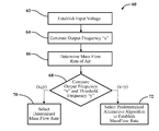
- FIG. 2 depicts a method 60 of establishing a mass flow rate of air entering the engine 14 via the system 20 , as described with respect to FIG. 1 .
- the method commences in frame 62 , where it includes establishing an input voltage by the energy supply device 30 to energize the MAF sensor 26 .
- the method proceeds to frame 64 , where it includes generating an output frequency “x” via the MAF sensor 26 in response to the air flow 24 inside the duct 28 .
- the output frequency “x” generated by the MAF sensor 26 is indicative of the flow rate of the air mass entering the engine 14 .
- the method advances to frame 66 .
- the method includes determining the mass flow rate of air entering the engine 14 using the generated output frequency “x”.
- the method proceeds to frame 68 where it includes comparing the generated output frequency “x” with a predetermined threshold output frequency “y” that corresponds to the established input voltage.
- the result of the comparison made in frame 68 is indicated as “x ⁇ y” if the generated output frequency “x” is determined to be at or above the predetermined threshold output frequency “y”, and as “x ⁇ y” if the generated output frequency is determined to be below the predetermined threshold output frequency.
- the method moves to frame 70 , where it includes selecting the determined mass flow rate of air as the established flow rate of the air mass entering the engine 14 .
- the method proceeds to frame 72 where it includes selecting the predetermined alternative algorithm to generate the established flow rate of the air mass entering the engine 14 .
- the predetermined alternative algorithm may employ the look-up table 54 that includes a range of engine speed, engine fueling rate, and engine volumetric efficiency values versus flow rate values of the air mass entering the engine 14 .
- established flow rate of the air mass entering the engine 14 may be used by the controller 46 to regulate the combustion process of the engine itself and/or be used to regulate other devices whose operation is influenced by the air mass flow rate.
- the established flow rate of the air mass may also be used to regulate the regeneration of the exhaust after-treatment device 44 .
Landscapes
- Engineering & Computer Science (AREA)
- Physics & Mathematics (AREA)
- Fluid Mechanics (AREA)
- General Physics & Mathematics (AREA)
- Chemical & Material Sciences (AREA)
- Combustion & Propulsion (AREA)
- Mechanical Engineering (AREA)
- General Engineering & Computer Science (AREA)
- Combined Controls Of Internal Combustion Engines (AREA)
- Processes For Solid Components From Exhaust (AREA)
- Supercharger (AREA)
- Exhaust Gas After Treatment (AREA)
Abstract
Description
Claims (20)
Priority Applications (3)
| Application Number | Priority Date | Filing Date | Title |
|---|---|---|---|
| US13/102,170 US8424372B2 (en) | 2011-05-06 | 2011-05-06 | System and method for establishing a mass flow rate of air entering an engine |
| DE102012207360.4A DE102012207360B4 (en) | 2011-05-06 | 2012-05-03 | SYSTEM AND METHOD FOR PROVIDING A MASS FLOW RATE OF AIR ENTERING A MOTOR |
| CN201210138069.1A CN102777278B (en) | 2011-05-06 | 2012-05-07 | For setting up the system and method for the mass flowrate of the air entering motor |
Applications Claiming Priority (1)
| Application Number | Priority Date | Filing Date | Title |
|---|---|---|---|
| US13/102,170 US8424372B2 (en) | 2011-05-06 | 2011-05-06 | System and method for establishing a mass flow rate of air entering an engine |
Publications (2)
| Publication Number | Publication Date |
|---|---|
| US20120279291A1 US20120279291A1 (en) | 2012-11-08 |
| US8424372B2 true US8424372B2 (en) | 2013-04-23 |
Family
ID=47019801
Family Applications (1)
| Application Number | Title | Priority Date | Filing Date |
|---|---|---|---|
| US13/102,170 Expired - Fee Related US8424372B2 (en) | 2011-05-06 | 2011-05-06 | System and method for establishing a mass flow rate of air entering an engine |
Country Status (3)
| Country | Link |
|---|---|
| US (1) | US8424372B2 (en) |
| CN (1) | CN102777278B (en) |
| DE (1) | DE102012207360B4 (en) |
Cited By (1)
| Publication number | Priority date | Publication date | Assignee | Title |
|---|---|---|---|---|
| US9441534B2 (en) * | 2014-10-09 | 2016-09-13 | GM Global Technology Operations LLC | Cooled two-stage turbocharging system |
Families Citing this family (1)
| Publication number | Priority date | Publication date | Assignee | Title |
|---|---|---|---|---|
| US10934960B2 (en) * | 2018-11-02 | 2021-03-02 | GM Global Technology Operations LLC | Method and system for estimating mass airflow using a mass airflow sensor |
Citations (2)
| Publication number | Priority date | Publication date | Assignee | Title |
|---|---|---|---|---|
| US20020108432A1 (en) * | 2001-02-13 | 2002-08-15 | Maloney Peter James | Frequency response test method for an in-vehicle air/fuel ratio sensor |
| US20060173607A1 (en) * | 2003-03-03 | 2006-08-03 | Noritaka Matsuo | Engine suction air flow rate measuring device |
Family Cites Families (6)
| Publication number | Priority date | Publication date | Assignee | Title |
|---|---|---|---|---|
| US5435180A (en) * | 1992-10-07 | 1995-07-25 | Hitachi, Ltd. | Method and system for measuring air flow rate |
| JP3935013B2 (en) * | 2002-07-19 | 2007-06-20 | 株式会社日立製作所 | Control device for internal combustion engine provided with output correction means for thermal airflow sensor |
| JP4367335B2 (en) * | 2004-12-27 | 2009-11-18 | 日産自動車株式会社 | Engine control device. |
| JP2008215131A (en) * | 2007-03-01 | 2008-09-18 | Toyota Motor Corp | Control device for internal combustion engine |
| GB2460397B (en) * | 2008-05-19 | 2012-12-12 | Ford Global Tech Llc | A Method and system for controlling the operation of an engine |
| CN101995279B (en) * | 2009-08-10 | 2012-07-18 | 上海捷程机电有限公司 | Thermal flow sensor |
-
2011
- 2011-05-06 US US13/102,170 patent/US8424372B2/en not_active Expired - Fee Related
-
2012
- 2012-05-03 DE DE102012207360.4A patent/DE102012207360B4/en not_active Expired - Fee Related
- 2012-05-07 CN CN201210138069.1A patent/CN102777278B/en not_active Expired - Fee Related
Patent Citations (2)
| Publication number | Priority date | Publication date | Assignee | Title |
|---|---|---|---|---|
| US20020108432A1 (en) * | 2001-02-13 | 2002-08-15 | Maloney Peter James | Frequency response test method for an in-vehicle air/fuel ratio sensor |
| US20060173607A1 (en) * | 2003-03-03 | 2006-08-03 | Noritaka Matsuo | Engine suction air flow rate measuring device |
Cited By (1)
| Publication number | Priority date | Publication date | Assignee | Title |
|---|---|---|---|---|
| US9441534B2 (en) * | 2014-10-09 | 2016-09-13 | GM Global Technology Operations LLC | Cooled two-stage turbocharging system |
Also Published As
| Publication number | Publication date |
|---|---|
| US20120279291A1 (en) | 2012-11-08 |
| DE102012207360B4 (en) | 2017-04-20 |
| CN102777278B (en) | 2016-01-20 |
| DE102012207360A1 (en) | 2012-11-08 |
| CN102777278A (en) | 2012-11-14 |
Similar Documents
| Publication | Publication Date | Title |
|---|---|---|
| US8649961B2 (en) | Method of diagnosing several systems and components by cycling the EGR valve | |
| JP4325704B2 (en) | Exhaust gas purification system for internal combustion engine | |
| US8156729B2 (en) | Variable engine out emission control roadmap | |
| US10995645B2 (en) | Exhaust aftertreatment system and method for regenerating a particulate filter | |
| US8875488B2 (en) | Internal combustion engine | |
| US9146210B2 (en) | Control system and method for heating an oxygen sensor | |
| US20100050757A1 (en) | Method and system to determine the efficiency of a diesel oxidation catalyst | |
| US10704519B2 (en) | Control device of hybrid vehicle | |
| CN105402042A (en) | Methods And Systems For Identifying Insufficient Combustion Based On Exhaust Gas Content | |
| JP2016114058A (en) | Multi-fuel engine system | |
| CN103982310A (en) | Systems and methods for compensating biodiesel fuel | |
| KR20140135110A (en) | Method and device for operating exhaust gas recirculation of a spontaneous ignition in an internal combustion engine, in particular for a motor vehicle | |
| GB2500598A (en) | Engine system comprising EGR and oxygen delivery system | |
| US20160153329A1 (en) | Particulate filter regeneration method of diesel hybrid vehicle | |
| CN115680842A (en) | Controller for a drive train for controlling the ignition time and the air ratio | |
| US7980062B2 (en) | Cold start white smoke aftertreatment protection | |
| US8141348B2 (en) | Engine after-treatment controls using dosing below catalyst light-off temperature | |
| US8424372B2 (en) | System and method for establishing a mass flow rate of air entering an engine | |
| US20130186071A1 (en) | Fuel supply method | |
| CN110778383A (en) | Method for regenerating particulate filters in exhaust gas installations of gasoline engines | |
| US20150292423A1 (en) | Egr operation method and system for increased drivability | |
| CN110500220A (en) | Method for reducing particle emissions in the case of a cold start of an internal combustion engine | |
| US20120102921A1 (en) | System and method for controlling regeneration of an exhaust after-treatment device | |
| US8069656B2 (en) | Method of controlling hydrocarbon accumulation in a particulate filter under certain operating conditions | |
| US20100281852A1 (en) | Filter Regeneration System and Method |
Legal Events
| Date | Code | Title | Description |
|---|---|---|---|
| AS | Assignment |
Owner name: GM GLOBAL TECHNOLOGY OPERATIONS LLC, MICHIGAN Free format text: ASSIGNMENT OF ASSIGNORS INTEREST;ASSIGNORS:SARSEN, DOUGLAS CHRISTOPHER;WHITT, CHRISTOPHER;DARR, REBECCA J.;REEL/FRAME:026238/0276 Effective date: 20110428 |
|
| AS | Assignment |
Owner name: WILMINGTON TRUST COMPANY, DELAWARE Free format text: SECURITY AGREEMENT;ASSIGNOR:GM GLOBAL TECHNOLOGY OPERATIONS LLC;REEL/FRAME:028466/0870 Effective date: 20101027 |
|
| FEPP | Fee payment procedure |
Free format text: PAYOR NUMBER ASSIGNED (ORIGINAL EVENT CODE: ASPN); ENTITY STATUS OF PATENT OWNER: LARGE ENTITY |
|
| STCF | Information on status: patent grant |
Free format text: PATENTED CASE |
|
| AS | Assignment |
Owner name: GM GLOBAL TECHNOLOGY OPERATIONS LLC, MICHIGAN Free format text: RELEASE BY SECURED PARTY;ASSIGNOR:WILMINGTON TRUST COMPANY;REEL/FRAME:034186/0776 Effective date: 20141017 |
|
| FPAY | Fee payment |
Year of fee payment: 4 |
|
| FEPP | Fee payment procedure |
Free format text: MAINTENANCE FEE REMINDER MAILED (ORIGINAL EVENT CODE: REM.); ENTITY STATUS OF PATENT OWNER: LARGE ENTITY |
|
| LAPS | Lapse for failure to pay maintenance fees |
Free format text: PATENT EXPIRED FOR FAILURE TO PAY MAINTENANCE FEES (ORIGINAL EVENT CODE: EXP.); ENTITY STATUS OF PATENT OWNER: LARGE ENTITY |
|
| STCH | Information on status: patent discontinuation |
Free format text: PATENT EXPIRED DUE TO NONPAYMENT OF MAINTENANCE FEES UNDER 37 CFR 1.362 |
|
| FP | Lapsed due to failure to pay maintenance fee |
Effective date: 20210423 |