US8419551B2 - Rotary shaft device - Google Patents
Rotary shaft device Download PDFInfo
- Publication number
- US8419551B2 US8419551B2 US13/093,071 US201113093071A US8419551B2 US 8419551 B2 US8419551 B2 US 8419551B2 US 201113093071 A US201113093071 A US 201113093071A US 8419551 B2 US8419551 B2 US 8419551B2
- Authority
- US
- United States
- Prior art keywords
- rotary shaft
- communication holes
- disk
- joint disk
- ring
- Prior art date
- Legal status (The legal status is an assumption and is not a legal conclusion. Google has not performed a legal analysis and makes no representation as to the accuracy of the status listed.)
- Active, expires
Links
Images


Classifications
-
- B—PERFORMING OPERATIONS; TRANSPORTING
- B23—MACHINE TOOLS; METAL-WORKING NOT OTHERWISE PROVIDED FOR
- B23Q—DETAILS, COMPONENTS, OR ACCESSORIES FOR MACHINE TOOLS, e.g. ARRANGEMENTS FOR COPYING OR CONTROLLING; MACHINE TOOLS IN GENERAL CHARACTERISED BY THE CONSTRUCTION OF PARTICULAR DETAILS OR COMPONENTS; COMBINATIONS OR ASSOCIATIONS OF METAL-WORKING MACHINES, NOT DIRECTED TO A PARTICULAR RESULT
- B23Q1/00—Members which are comprised in the general build-up of a form of machine, particularly relatively large fixed members
- B23Q1/0009—Energy-transferring means or control lines for movable machine parts; Control panels or boxes; Control parts
- B23Q1/0018—Energy-transferring means or control lines for movable machine parts; Control panels or boxes; Control parts comprising hydraulic means
- B23Q1/0027—Energy-transferring means or control lines for movable machine parts; Control panels or boxes; Control parts comprising hydraulic means between moving parts between which an uninterrupted energy-transfer connection is maintained
-
- B—PERFORMING OPERATIONS; TRANSPORTING
- B23—MACHINE TOOLS; METAL-WORKING NOT OTHERWISE PROVIDED FOR
- B23Q—DETAILS, COMPONENTS, OR ACCESSORIES FOR MACHINE TOOLS, e.g. ARRANGEMENTS FOR COPYING OR CONTROLLING; MACHINE TOOLS IN GENERAL CHARACTERISED BY THE CONSTRUCTION OF PARTICULAR DETAILS OR COMPONENTS; COMBINATIONS OR ASSOCIATIONS OF METAL-WORKING MACHINES, NOT DIRECTED TO A PARTICULAR RESULT
- B23Q11/00—Accessories fitted to machine tools for keeping tools or parts of the machine in good working condition or for cooling work; Safety devices specially combined with or arranged in, or specially adapted for use in connection with, machine tools
- B23Q11/12—Arrangements for cooling or lubricating parts of the machine
- B23Q11/126—Arrangements for cooling or lubricating parts of the machine for cooling only
- B23Q11/127—Arrangements for cooling or lubricating parts of the machine for cooling only for cooling motors or spindles
-
- F—MECHANICAL ENGINEERING; LIGHTING; HEATING; WEAPONS; BLASTING
- F16—ENGINEERING ELEMENTS AND UNITS; GENERAL MEASURES FOR PRODUCING AND MAINTAINING EFFECTIVE FUNCTIONING OF MACHINES OR INSTALLATIONS; THERMAL INSULATION IN GENERAL
- F16L—PIPES; JOINTS OR FITTINGS FOR PIPES; SUPPORTS FOR PIPES, CABLES OR PROTECTIVE TUBING; MEANS FOR THERMAL INSULATION IN GENERAL
- F16L39/00—Joints or fittings for double-walled or multi-channel pipes or pipe assemblies
- F16L39/06—Joints or fittings for double-walled or multi-channel pipes or pipe assemblies of the multiline swivel type, e.g. comprising a plurality of axially mounted modules
-
- F—MECHANICAL ENGINEERING; LIGHTING; HEATING; WEAPONS; BLASTING
- F16—ENGINEERING ELEMENTS AND UNITS; GENERAL MEASURES FOR PRODUCING AND MAINTAINING EFFECTIVE FUNCTIONING OF MACHINES OR INSTALLATIONS; THERMAL INSULATION IN GENERAL
- F16D—COUPLINGS FOR TRANSMITTING ROTATION; CLUTCHES; BRAKES
- F16D2300/00—Special features for couplings or clutches
- F16D2300/02—Overheat protection, i.e. means for protection against overheating
- F16D2300/021—Cooling features not provided for in group F16D13/72 or F16D25/123, e.g. heat transfer details
- F16D2300/0214—Oil or fluid cooling
Definitions
- the present invention relates to a rotary shaft device arranged in a main spindle of a machine tool and the like and rotatably supporting a rotary shaft including reciprocating flow passages for fluid.
- a main spindle for a machine tool for example, reciprocating flow passages for fluid are arranged inside a rotary shaft for the purpose of cooling, and it is configured to supply the reciprocating flow passages with fluid through a rotary joint.
- a rotary joint as described in JP-A-S51-100323, a structure is known in which a plurality of annular oil passage grooves are formed concentrically between end faces of a pair of disks facing with each other. Further, O-rings are provided between the adjacent annular oil passage grooves, and passage openings connected to each annular oil passage groove are opened in the outer end surface of the each disk to allow the fluid to be supplied.
- the rotary joint described in JP-A-S51-100323 is of a one-way structure in which the fluid passes from one disk to the other disk. Therefore, it is difficult to apply the known structure to a rotary shaft provided with reciprocating flow passages inside thereof such as a main spindle of a machine tool.
- a rotary shaft provided with reciprocating flow passages rotates at a high speed
- the fluid pressure increases inside the joint on the discharge side because of the pressure caused by the difference in the radius of a forward passage and a backward passage.
- the internal pressure of the rotary joint increases, which may lead to fluid leaking.
- the drastic drop of the fluid pressure inside the forward passage or inside the joint may cause an occurrence of cavitation.
- the object of the present invention is to provide a rotary shaft device capable of inhibiting an occurrence of leakage and supplying fluid stably even if a rotary shaft provided with reciprocating flow passages for fluid rotates at a high speed.
- a first aspect of the present invention is a rotary shaft device including a rotary joint having a front joint disk and a rear joint disk.
- the front joint disk is arranged in a rear end face of a rotary shaft, which is provided with reciprocating flow passages.
- the rear joint disk is arranged so as to oppose the front joint disk and capable of being pressed against the front joint disk by a pressing part at a predetermined pressure.
- the front joint disk and the rear joint disk are provided with forward communication holes connected to a forward passages side of the reciprocating flow passages, and backward communication holes connected to a backward passages side of the reciprocating flow passages respectively.
- either the front joint disk or the rear joint disk opposing with each other has a ring-shaped inner seal projecting and abutting upon the opponent face on the axis side of the joint disk in the pressing state by the pressing part.
- Either the front joint disk or the rear joint disk opposing with each other also has a ring-shaped outer seal projecting, positioned concentrically with the inner seal, and abutting upon the opponent face on the outer periphery side of the joint disk in the pressing state by the pressing part.
- a ring-shaped inner space and a ring-shaped outer space are adjacently arranged concentrically with each other between the inner seal and the outer seal.
- the ring-shaped inner space communicates with the forward communication holes or the backward communication holes.
- the ring-shaped outer space also communicates with the forward communication holes or the backward communication holes.
- the forward and the backward communication holes at least in the front joint disk are arranged at an equal distance in the peripheral direction of the opposing face.
- a second aspect of the present invention is the rotary shaft device according to the first aspect in which a ring-shaped middle seal separates the inner space and the outer space, and being projectingly arranged concentrically with the inner seal and the outer seal at least in either of the faces opposing with each other.
- a third aspect of the present invention is the rotary shaft device according to the second aspect in which the middle seal is arranged to project less than the inner seal and the outer seal so as to form a gap through which the inner space and the outer space communicate with each other in the pressing state.
- a fourth aspect of the present invention is the rotary shaft device according to the third aspect in which the gap is variable according to the number of revolution of the rotary shaft.
- a fifth aspect of the present invention is the rotary shaft device according to any of the preceding aspects in which the front joint disk is provided with a throttle mechanism reducing a flow passage cross-sectional area of the backward communication holes on the far side of the rotation center of the rotary shaft as the number of revolution of the rotary shaft increases.
- a sixth aspect of the present invention is the rotary shaft device according to the fifth aspect in which the throttle mechanism is formed of a slide body and an energizing part.
- the slide body crosses the backward communication hole, and being slidable in the radial direction of the front joint disk.
- the energizing part energizes the slide body in the slide direction increasing the flow passage cross-sectional area.
- a seventh aspect of the present invention is the rotary shaft device according to the first aspect in which the inner space and the outer space are formed so as to be united.
- a eighth aspect of the present invention is the rotary shaft device according to the first aspect in which the rear end of at least either of the forward communication holes and the backward communication holes arranged in the front joint disk are arranged lower than a radial position of the reciprocating flow passages connected in the radial direction of the rotary shaft.
- the rotation balance is improved. Therefore, leakage hardly occurs because of arranging adjacently even if the rotary shaft provided with the reciprocating passages rotates at a high speed.
- leakage of fluid can be prevented more effectively in addition to the effect of the first aspect of the present invention.
- sealing resistance can be reduced even if the middle seal is provided. Further, an increase in the pressure of the outer space caused by the centrifugal force can be suppressed in addition to the effect of the second aspect.
- the pressure drop of the inner space and the pressure rise of the outer space caused by the centrifugal force with an increase in the number of revolution can be improved gradually in addition to the effect of the third aspect.
- the fluid pressure drop and changes in the flow rate inside the rotary shaft can be suppressed by adoption of the throttle mechanism in addition to the effect of either of the first to fourth aspect.
- the flow rate of the fluid to the reciprocating flow passages of the rotary shaft is increased.
- the fluid is the cooling liquid, the heat transfer coefficient is increased. Therefore, cooling efficiency can be improved in addition to the effect of the first aspect.
- the fluid can be supplied to the reciprocating passages stably without disturbing flow-in by cavitation, and leakage from the outer seal due to an increase in pressure at an outlet can be prevented in addition to the effect of the first aspect.
- FIG. 1 is a vertical cross-sectional view of a rotary shaft device
- FIG. 2A is an explanatory drawing showing the end face of a front joint disk
- FIG. 2B is an explanatory drawing showing the end face of a rear joint disk
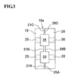
- FIG. 3 is an explanatory drawing for a variant of a rotary joint
- FIG. 4 is an explanatory drawing for a variant of the rotary joint
- FIG. 5 is an explanatory drawing for a variant of the rotary joint
- FIG. 6A is an explanatory drawing for a variant of the rotary joint
- FIG. 6B is an explanatory drawing for a throttle mechanism.
- FIG. 7 is an explanatory drawing for a variant of the rotary joint
- FIG. 8 is an explanatory drawing for a variant of the rotary joint
- FIG. 9 is an explanatory drawing for a variant of a connection part of communication holes and reciprocating passages of a rotary joint.
- FIG. 10 is an explanatory drawing for a variant of the reciprocating passages.
- FIG. 1 is a vertical cross-sectional view showing an example of a rotary shaft device used for a main spindle of a machine tool.
- the rotary shaft device 1 includes a rotary shaft 3 rotatably supported by a housing 2 through front and rear ball bearings 4 , 4 and rotatably driven by a motor not shown.
- an accommodation hole 3 a is formed for a draw bar operating a chuck device, and arranged in the end of the rotary shaft 3 .
- the reciprocating flow passage 5 is formed in a horizontal U-shape composed of a forward passage 6 , a backward passage 7 and a connection passage 8 .
- the forward passage 6 is in parallel with the axis of the rotary shaft 3 , and positioned on the near side of the axis.
- the backward passage 7 is also in parallel with the axis, and positioned on the far side of the axis.
- the connection passage 8 extends in the radial direction and connects the front ends (the left side in FIG. 1 is to be referred to as the front side) of the forward passage 6 and the backward passage 7 , and is arranged by a plural number at an equal distance in the peripheral direction.
- a cylinder 9 is connected to the rear part of the housing 2 , and a piston 10 is held in the center of the cylinder 9 .
- a plurality of L-shape inner flow passages 11 are formed on the concentric circle with the forward passages 6 of the rotary shaft 3 in parallel with the axis. The rear ends of the inner flow passages 11 are bent to extend in the radial direction.
- a plurality of L-shape outer flow passages 12 are formed on the concentric circle with the backward passages 7 of the rotary shaft 3 in parallel with the axis. The rear ends of the outer flow passages 12 are bent to extend in the radial direction.
- the rear ends of the inner flow passages 11 are connected to a rear annular groove 13 circumferentially arranged in the outer periphery of the piston 10
- the rear ends of the outer flow passages 12 are connected to a front annular groove 14 circumferentially arranged in the outer periphery of the piston 10 respectively.
- an inward flow passage 15 and an outward flow passage 16 are formed so that the inward flow passage 15 is connected to the rear annular groove 13 , and the outward flow passage 16 is connected to the front annular groove 14 .
- a rotary joint 18 is arranged between the rotary shaft 3 and the piston 10 .
- the rotary joint 18 is composed of a front joint disk 19 and a rear joint disk 20 .
- the front joint disk 19 is fixed to the rear end face of the rotary shaft 3
- the rear joint disk 20 is fixed to the front end face of the piston 10 .
- an inner seal 21 A, a middle seal 21 B and an outer seal 21 C are formed as ring-shaped projections.
- the inner seal 21 A positioned innermost in the radial direction and an outer seal 21 C positioned outermost are projectingly arranged concentrically respectively, as shown in FIG. 2A .
- the middle seal 21 B positioned between the inner seal 21 A and the outer seal 21 C is projectingly arranged concentrically as well.
- forward communication holes 23 , 23 , . . . concentrically communicating with the forward passages 6 of the reciprocating flow passages 5 are formed in a groove 22 provided between the inner seal 21 A and the middle seal 21 B.
- backward communication holes 25 , 25 , . . . concentrically communicating with the backward passages 7 of the reciprocating flow passages 5 are formed in a groove 24 provided between the middle seal 21 B and the outer seal 21 C.
- the forward passages 6 and the backward passages 7 are arranged at an equal distance in the peripheral direction, and positioned on straight lines in the radial direction of the rotary shaft 3 . Therefore, the forward communication holes 23 and the backward communication holes 25 are arranged at an equal distance in the peripheral direction as shown in FIG. 2A .
- an inner seal 26 A, a middle seal 26 B and an outer seal 26 C are formed as ring-shaped projections.
- the inner seal 26 A positioned innermost in the radial direction and an outer seal 26 C positioned outermost are projectingly arranged concentrically respectively, as shown in FIG. 2B .
- the middle seal 26 B positioned between the inner seal 26 A and the outer seal 26 C is projectingly arranged concentrically as well.
- forward communication holes 28 , 28 . . . concentrically communicating with the inner flow passages 11 are formed in a groove 27 provided between the inner seal 26 A and the middle seal 26 B.
- backward communication holes 30 , 30 , . . . concentrically communicating with the outer flow passages 12 are formed in a groove 29 provided between the middle seal 26 B and the outer seal 26 C.
- each forward communication hole 28 and the backward communication hole 30 are arranged at an equal distance in the peripheral direction inside the respective grooves 27 , 29 .
- a cylinder chamber 31 is provided behind the piston 10 , and forms a pressing part to press the piston 10 forward by means of supplying the fluid of a predetermined pressure P from the outside through a supply passage 32 formed in the cylinder 9 .
- the rear joint disk 20 presses against the front joint disk 19 .
- the inner seals 21 A, 26 A, the middle seals 21 B, 26 B, and the outer seals 21 C, 26 C are made to abut upon each other to seal the inner and outer peripheries and the middle of both the joint disks 19 , 20 .
- a ring-shaped inner space 33 can be formed by the opposing grooves 22 , 27
- a ring-shaped outer space 34 can be formed by the opposing grooves 24 , 29 respectively.
- a reference numeral 35 is a rotation preventing pin whose ends are inserted into the piston 10 and the cylinder 9 with play.
- the rear joint disk 20 presses against the front joint disk 19 by means of supplying the fluid to the cylinder chamber 31 in a state of rotation of the rotary shaft 3 , wherein the cooling liquid enters the inner space 33 from the respective inner flow passages 11 through the respective forward communication holes 28 of the rear joint disk 20 if the cooling liquid supplied to the inward flow passage 15 from the supply device. Further, the cooling liquid enters the respective reciprocating flow passages 5 from the respective forward communication holes 23 , 23 of the front joint disk 19 , passes the forward passages 6 , and the connection passages 8 , the backward passages 7 in order, and thereby cools the rotary shaft 3 .
- the cooling liquid enters the outer space 34 through the respective backward communication holes 25 of the front joint disk 19 , passes the respective outer flow passages 12 through the respective backward communication holes 30 of the rear joint disk 20 , and returns to the supply device from the outward flow passage 16 .
- the cooling liquid can be delivered stably from the rear joint disk 20 to the front joint disk 19 , even if the front joint disk 19 rotates at a high speed along with the rotary shaft 3 .
- the reciprocating flow passages 5 in the rotary shaft 3 as well as the forward communication holes 23 and the backward communication holes 25 of the front joint disk 19 in the rotary joint 18 are arranged at an equal distance in the peripheral direction.
- the rotation balance is improved further because the forward communication holes 28 and the backward communication holes 30 are arranged with good balance in the peripheral direction in the grooves 27 and 29 respectively in the rear joint disk 20 .
- the ring-shaped inner seals 21 A, 26 A and the ring-shaped outer seals 21 C, 26 C are projectingly arranged, and are concentric with the faces of the front joint disk 19 and the rear joint disk 20 respectively.
- the ring-shaped inner seals 21 A, 26 A abuts upon each other on the axis side of the opposing faces, and the ring-shaped outer seals 21 C, 26 C abuts upon each other on the outer periphery side of the opposing faces in the pressing state caused by the pressing part.
- the ring-shaped inner space 33 communicates with the forward communication holes 23 , 28 and the ring-shaped outer space 34 communicates with the backward communication holes 25 , 30 .
- the ring-shaped inner space 33 and the ring-shaped outer space 34 are adjacently arranged concentrically between the inner seals 21 A, 26 A and the outer seals 21 C, 26 C.
- the forward communication holes 23 and the backward communication holes 25 in the reciprocating flow passages 5 and the front joint disk 19 are arranged at an equal distance in the peripheral direction of the opposing faces. Therefore, the rotation balance is improved, and leakage hardly occurs because of the arrangement of the forward communication holes 23 and the backward communication holes 25 , even if the rotary shaft 3 provided with the reciprocating passages 5 rotates at a high speed.
- the ring-shaped middle seals 21 B, 26 B separating the inner space 33 and the outer space 34 are arranged adjacently concentrically with the inner seals 21 A, 26 A and the outer seals 21 C, 26 C on the faces of the front joint disk 19 and the rear joint disk 20 opposing with each other. Therefore, leakage of the cooling liquid can be prevented more effectively.
- the middle seals 21 B, 26 B are arranged to project slightly less than other seals so as to reserve some gap between the front and rear middle seals 21 B, 26 B in a pressing state of the rear joint disk 20 .
- middle seals 21 B, 26 B are arranged to project less than the inner seals 21 A, 26 A and the outer seals 21 C, 26 C so as to form the gap through which the inner space 33 and the outer space 34 communicate with each other in the pressing state, sealing resistance can be reduced even if the middle seals 21 B, 26 B are provided. Further, the pressure of the outer space 34 caused by the centrifugal force can be increased gradually.
- the middle seal 26 B of the rear joint disk 20 side is made a separate body and arranged so as to move forward and backward with respect to the rear joint disk 20 .
- An actuator such as a hydraulic cylinder 37 and the like, is connected to a cylinder chamber 36 arranged behind the middle seal 26 B so as to change the projection position according to the number of revolution of the rotary shaft 3 .
- the sealing resistance can be reduced.
- the pressure drop of the inner space 33 and an increase in the pressure of the outer space 34 caused by the centrifugal force can be suppressed when the number of revolution increases.
- the middle seal to be moved may be provided in the front joint disk.
- a ring-shaped united space 38 is formed and units the inner space and the outer space by eliminating the middle seal. Further, in this case, with respect to the forward communication holes 28 and the backward communication holes 30 of the rear joint disk 20 , the forward flow side and the backward flow side of the fluid may be reversed.
- an accommodation part 40 is continuously arranged on the rotation center side in the backward communication holes 25 on the far side from the rotation center of the front joint disk 19 .
- the accommodation part 40 accommodates a slide body 39 , which is slidable in the radial direction.
- a coil spring 41 is arranged as an energizing part energizing the slide body 39 from the outside in the radial direction toward the accommodation part 40 side so as to form a throttle mechanism.
- the throttle mechanism is formed of the slide body 39 and the coil spring 41 , which is operated by the centrifugal force generated by rotation of the rotary shaft 3 . Therefore, the throttle mechanism can be obtained easily and in a rational manner.
- the fluid pressure drop and changes in the flow rate inside the rotary shaft 3 can be suppressed. More specifically, it can be achieved by making the hole diameter of the flow passages and the communication holes of the former smaller than the hole diameter of the flow passages and the communication holes of the latter, by making the number of the flow passage and the communication hole less, or by making the length of the flow passages and the communication holes longer.
- outer seal and the inner seal are not required to be arranged in both the front joint disk and the rear joint disk, and may be arranged only in either of them as shown in a rotary joint 18 e shown in FIG. 7 .
- the same is true with respect to the middle seal, and it is not necessary to projectingly arrange it in both.
- the rear end of the communication holes arranged in the front joint disk is arranged less than the radial position of the reciprocating flow passages (the position in a radius smaller than said radius) in the radial direction of the rotary shaft. Therefore, the fluid can be supplied to the reciprocating passages stably without disturbing flow-in by cavitation, and leakage from the outer seal caused by an increasing in the pressure at an outlet can be prevented.
- a rotary joint 18 f shown in FIG. 8 has the constitution in which the communication holes 23 , 25 formed in the front joint disk 19 are inclined inward respectively in the radial direction of the rotary shaft 3 so that the rear ends on the inner space 33 and the outer space 34 side are in the positions with smaller diameter than the radial position of the forward passages 6 and the backward passages 7 with respect to the front ends communicating with the forward passages 6 and the backward passages 7 .
- a rotary joint 18 h shown in FIG. 10 has the constitution in which the rear ends of the forward passages 6 and the backward passages 7 are inclined to the smaller radius side in the radial direction of the rotary shaft 3 and are connected respectively to the communication holes 23 , 25 parallel with the axis of the rotary shaft 3 .
- the constitution may be arranged in either one only of the forward communication holes and the backward communication holes, or the constitution applied may be different between the forward communication holes and the backward communication holes.
- rotary shaft device other structures are not limited to the configurations described above.
- an elastic body such as a coil spring, a disk spring and the like
- the forward communication holes and the backward communication holes are arranged at an equal distance in the peripheral direction in both of the front joint disk and the rear joint disk of the rotary joint in addition to the reciprocating flow passages of the rotary shaft.
- the rotation balance is improved as far as the flow passages and the communication holes are arranged at an equal distance at least in the reciprocating flow passages and the front joint disk. Therefore, equal arrangement may not be applied for the rear joint disk.
- the reciprocating flow passage is not limited to the structure of arranging inside the rotary shaft.
- the gap between the draw bar and the accommodation hole may be used for the forward passage, or a sleeve may be inserted into the accommodation hole, and the gap between the inner surface of the accommodation hole and the outer surface of the sleeve may be made the forward passage or the backward passage.
- the plural reciprocating flow passages are made one set, and plural sets may be arranged at an equal distance, or combinations thereof are also applicable.
- front joint disk or the rear joint disk is not limited to a part formed of one body.
- it may be a part in which the forward communication hole side and the backward communication hole side are separated respectively.
Landscapes
- Engineering & Computer Science (AREA)
- Mechanical Engineering (AREA)
- General Engineering & Computer Science (AREA)
- Joints Allowing Movement (AREA)
- Auxiliary Devices For Machine Tools (AREA)
- Mounting Of Bearings Or Others (AREA)
Abstract
Description
Claims (8)
Applications Claiming Priority (2)
| Application Number | Priority Date | Filing Date | Title |
|---|---|---|---|
| JP2010-113457 | 2010-05-17 | ||
| JP2010113457A JP5456573B2 (en) | 2010-05-17 | 2010-05-17 | Rotating shaft device |
Publications (2)
| Publication Number | Publication Date |
|---|---|
| US20110281658A1 US20110281658A1 (en) | 2011-11-17 |
| US8419551B2 true US8419551B2 (en) | 2013-04-16 |
Family
ID=44859882
Family Applications (1)
| Application Number | Title | Priority Date | Filing Date |
|---|---|---|---|
| US13/093,071 Active 2031-05-10 US8419551B2 (en) | 2010-05-17 | 2011-04-25 | Rotary shaft device |
Country Status (5)
| Country | Link |
|---|---|
| US (1) | US8419551B2 (en) |
| JP (1) | JP5456573B2 (en) |
| CN (1) | CN102248185B (en) |
| DE (1) | DE102011075964B4 (en) |
| IT (1) | ITMI20110724A1 (en) |
Families Citing this family (1)
| Publication number | Priority date | Publication date | Assignee | Title |
|---|---|---|---|---|
| JP6463297B2 (en) * | 2016-04-19 | 2019-01-30 | 株式会社ソディック | Machine tool spindle equipment |
Citations (5)
| Publication number | Priority date | Publication date | Assignee | Title |
|---|---|---|---|---|
| US3950017A (en) * | 1974-04-29 | 1976-04-13 | United Technologies Corporation | Leakproof connection for polyethylene tubing |
| JPS51100323A (en) | 1975-02-28 | 1976-09-04 | Kubota Ltd | YUATSUROOTARIJOINTO |
| DE19916106A1 (en) * | 1999-04-09 | 2000-10-26 | Mohammad Mohsen Saadat | Machine element for moving fluid under pressure or vacuum comprises two components which move relative to each other and have bores for passage of fluid, with seal having pairs of sealing lips located between components |
| US20080093842A1 (en) * | 2006-10-17 | 2008-04-24 | Zf Friedrichshafen Ag | Rotary leadthrough, especially for the drive train of a motor vehicle |
| US20100109320A1 (en) * | 2006-09-28 | 2010-05-06 | Stokes Bio Limited | Microfluidic connector |
Family Cites Families (2)
| Publication number | Priority date | Publication date | Assignee | Title |
|---|---|---|---|---|
| JP4637321B2 (en) | 2000-05-23 | 2011-02-23 | 東芝機械株式会社 | Rotary joint |
| JP2006043817A (en) | 2004-08-04 | 2006-02-16 | Toru Nishikazu | Cooling structure of main spindle |
-
2010
- 2010-05-17 JP JP2010113457A patent/JP5456573B2/en active Active
-
2011
- 2011-04-25 US US13/093,071 patent/US8419551B2/en active Active
- 2011-04-29 IT IT000724A patent/ITMI20110724A1/en unknown
- 2011-05-16 CN CN201110126536.4A patent/CN102248185B/en active Active
- 2011-05-17 DE DE102011075964.6A patent/DE102011075964B4/en active Active
Patent Citations (5)
| Publication number | Priority date | Publication date | Assignee | Title |
|---|---|---|---|---|
| US3950017A (en) * | 1974-04-29 | 1976-04-13 | United Technologies Corporation | Leakproof connection for polyethylene tubing |
| JPS51100323A (en) | 1975-02-28 | 1976-09-04 | Kubota Ltd | YUATSUROOTARIJOINTO |
| DE19916106A1 (en) * | 1999-04-09 | 2000-10-26 | Mohammad Mohsen Saadat | Machine element for moving fluid under pressure or vacuum comprises two components which move relative to each other and have bores for passage of fluid, with seal having pairs of sealing lips located between components |
| US20100109320A1 (en) * | 2006-09-28 | 2010-05-06 | Stokes Bio Limited | Microfluidic connector |
| US20080093842A1 (en) * | 2006-10-17 | 2008-04-24 | Zf Friedrichshafen Ag | Rotary leadthrough, especially for the drive train of a motor vehicle |
Also Published As
| Publication number | Publication date |
|---|---|
| DE102011075964A1 (en) | 2011-11-17 |
| DE102011075964B4 (en) | 2022-11-10 |
| CN102248185A (en) | 2011-11-23 |
| CN102248185B (en) | 2015-01-07 |
| ITMI20110724A1 (en) | 2011-11-18 |
| JP2011241880A (en) | 2011-12-01 |
| US20110281658A1 (en) | 2011-11-17 |
| JP5456573B2 (en) | 2014-04-02 |
Similar Documents
| Publication | Publication Date | Title |
|---|---|---|
| CN110553081B (en) | Hydraulic reversing valve and hydraulic reversing device | |
| CN101668959B (en) | Main clutch hub, and double clutch comprising such a main clutch hub | |
| US20170133912A1 (en) | Drive device | |
| JP5680254B2 (en) | Lubrication structure of friction engagement element in automatic transmission | |
| JP2006162061A (en) | Hydraulic double clutch | |
| RU2008121806A (en) | DISK BRAKE AND LIQUID SHIRT FOR HIM | |
| JP2009536711A (en) | Gerotor motor and brake assembly | |
| CN104428497A (en) | A concentric camshaft arrangement | |
| US8464644B2 (en) | Rotary table assembly | |
| JP2013038994A (en) | Rotary electric machine | |
| JPH10141209A (en) | Cam motor device | |
| JP5911269B2 (en) | Especially a pressure control valve for controlling the clutch of an automotive automatic transmission | |
| US20130149181A1 (en) | Distributor assembly for two-speed gerotor device | |
| US8419551B2 (en) | Rotary shaft device | |
| JP5917536B2 (en) | Fluid device with pressure roller pocket | |
| CN103174769A (en) | Wet clutch | |
| CN107914566A (en) | Double clutch and hybrid module | |
| EP2516855A2 (en) | Hydraulic machine with oil dams | |
| KR102680620B1 (en) | Hybrid drive module | |
| JP2014126020A (en) | Axial piston motor | |
| JP6209938B2 (en) | Cooling structure of rotating electric machine | |
| CN211082621U (en) | Double clutch | |
| CN113000868B (en) | Assembly for electric spindle with hydraulic cylinder and central cooling function | |
| US20170248241A1 (en) | Distribution device for a hydraulic machine | |
| JP5087580B2 (en) | Construction machinery hydraulic motor |
Legal Events
| Date | Code | Title | Description |
|---|---|---|---|
| AS | Assignment |
Owner name: OKUMA CORPORATION, JAPAN Free format text: ASSIGNMENT OF ASSIGNORS INTEREST;ASSIGNOR:NORIHISA, TAKASHI;REEL/FRAME:026174/0006 Effective date: 20110406 |
|
| STCF | Information on status: patent grant |
Free format text: PATENTED CASE |
|
| FEPP | Fee payment procedure |
Free format text: PAYOR NUMBER ASSIGNED (ORIGINAL EVENT CODE: ASPN); ENTITY STATUS OF PATENT OWNER: LARGE ENTITY |
|
| FPAY | Fee payment |
Year of fee payment: 4 |
|
| MAFP | Maintenance fee payment |
Free format text: PAYMENT OF MAINTENANCE FEE, 8TH YEAR, LARGE ENTITY (ORIGINAL EVENT CODE: M1552); ENTITY STATUS OF PATENT OWNER: LARGE ENTITY Year of fee payment: 8 |
|
| AS | Assignment |
Owner name: RIX CORPORATION, JAPAN Free format text: ASSIGNMENT OF ASSIGNORS INTEREST;ASSIGNOR:OKUMA CORPORATION;REEL/FRAME:068109/0292 Effective date: 20240517 |
|
| MAFP | Maintenance fee payment |
Free format text: PAYMENT OF MAINTENANCE FEE, 12TH YEAR, LARGE ENTITY (ORIGINAL EVENT CODE: M1553); ENTITY STATUS OF PATENT OWNER: LARGE ENTITY Year of fee payment: 12 |