US8415590B2 - Temperature controlled electronics tray - Google Patents
Temperature controlled electronics tray Download PDFInfo
- Publication number
- US8415590B2 US8415590B2 US12/251,337 US25133708A US8415590B2 US 8415590 B2 US8415590 B2 US 8415590B2 US 25133708 A US25133708 A US 25133708A US 8415590 B2 US8415590 B2 US 8415590B2
- Authority
- US
- United States
- Prior art keywords
- enclosure
- thermostat
- heated
- shroud
- temperature
- Prior art date
- Legal status (The legal status is an assumption and is not a legal conclusion. Google has not performed a legal analysis and makes no representation as to the accuracy of the status listed.)
- Active, expires
Links
Images


Classifications
-
- H—ELECTRICITY
- H05—ELECTRIC TECHNIQUES NOT OTHERWISE PROVIDED FOR
- H05B—ELECTRIC HEATING; ELECTRIC LIGHT SOURCES NOT OTHERWISE PROVIDED FOR; CIRCUIT ARRANGEMENTS FOR ELECTRIC LIGHT SOURCES, IN GENERAL
- H05B3/00—Ohmic-resistance heating
- H05B3/20—Heating elements having extended surface area substantially in a two-dimensional [2D] plane, e.g. plate-heater
- H05B3/22—Heating elements having extended surface area substantially in a two-dimensional [2D] plane, e.g. plate-heater non-flexible
- H05B3/28—Heating elements having extended surface area substantially in a two-dimensional [2D] plane, e.g. plate-heater non-flexible heating conductor embedded in insulating material
- H05B3/30—Heating elements having extended surface area substantially in a two-dimensional [2D] plane, e.g. plate-heater non-flexible heating conductor embedded in insulating material on or between metallic plates
Definitions
- the present disclosure is directed to a temperature-control device for stabilizing the temperature of electronics.
- the disclosure has particular utility in connection with controlling or minimizing condensation on electronic components that occurs due to frequent changes in atmospheric humidity experienced when traveling between different temperature/humidity regimes, e.g. as may be experienced in airplanes, and will be described in connection with such utility, although other utilities are contemplated.
- APU Auxiliary Power Unit
- the APU is controlled by the APU Engine Control Unit (ECU).
- ECU APU Engine Control Unit
- Conventional ECU's are exposed to environmental conditions that could adversely affect reliability. In particular excessive condensation may form on components inside the ECU during the rapid transition between flight environmental conditions (cold/dry) to ground environmental conditions (warm/humid).
- the ECU is affected by the cold flight environment because it shuts down when the APU shuts down during flight and thus heat is not continuously generated.
- the environment surrounding the controller unit is known to reach temperatures in the 20° F. to 30° F. range. During flight, when the ECU is off, it is “cold soaked” by the air surrounding the unit.
- the typical operating procedure calls for the APU and ECU to be turned on and the airplane's cargo doors to be immediately opened by the ground crew to begin the unloading/loading process. If the outside air is warm and humid, the cold soaked ECU will cause condensation inside the unit which could result in both the ECU and APU) to be inoperative. This situation is similar to the phenomena often observed when a cold glass of ice water appears to “perspire” on a warm humid day.
- the present disclosure in one embodiment provides an apparatus for housing electronic components comprising a heated enclosure comprising a bottom, a top, three sides, a substantially open front and a heating element for transmitting heat to enclosure surfaces; perforations located in the heated enclosure to facilitate the passage of air from one side of the heated enclosure to the other; a plenum connected to the perforations, the plenum being configured to transmit air between the outside and inside of the heated enclosure; control electronics comprising a power source and temperature monitoring and feedback circuitry; and insulation covering a heated portion of the heated enclosure.
- the present disclosure in another embodiment provides an apparatus for housing electronic components comprising a bottom having a ventilated portion; a heated shroud connected to and covering said bottom which together comprise a bottom-and-shroud combination; a plenum connected to the bottom, said plenum being configured to transmit air between the outside and inside of the bottom-and-shroud combination; control electronics comprising a power source and temperature monitoring and feedback circuitry; and insulation covering a heated portion of the shroud.
- an apparatus for housing electronic components comprising a bottom for supporting electronic components; a heated shroud connected to and covering said bottom which together comprise a bottom-and-shroud combination; a ventilation device connected to said bottom-and-shroud, said ventilation device being configured to transmit air between the outside and inside of the bottom-and-shroud combination; a temperature controller for maintaining an elevated temperature within said bottom-and-shroud; and thermal insulation for thermally isolating a heated portion of the shroud.
- FIG. 1 is a schematic depiction of the first embodiment and shows an elevational view from the front of the aircraft.
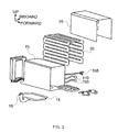
- FIG. 2 is a schematic depiction of the first embodiment and shows a side elevational view from the outboard side of the aircraft.
- FIG. 3 is an exploded diagram of the tray/heater assembly.
- FIG. 4 is a schematic showing the second embodiment and also depicts heat and airflow.
- FIG. 5 is a cross section of an angular view of the tray heater assembly, with a blown-up excerpt showing the attachment points of the thermostats and thermal fuse.
- FIGS. 6 and 7 schematically illustrate the electrical architecture and schematic of the control electronics and their interconnections.
- the specific problem that the embodiments address is that of condensation occurring when the aircraft transitions from a cold, dry air climate such as encountered at high altitudes, to a warm, moist air environment such as found on the ground during the summer months.
- Cold electronics that encounter a warm, moist environment will act as catalytic surfaces for condensation of water vapor to liquid water if the electronics' surface temperature is at or below the dew point of the air in immediate contact with the electronics.
- the “dew point” is the temperature of the air at which water vapor will condense out and form droplets.
- One possible solution is to keep the electronics warmer than the dew point thereby avoiding the deposition of liquid water on the electronic component surfaces.
- there are many potential solutions, but the solution described herein has particular benefits unique to the aircraft industry.
- FIG. 1 is a schematic depiction of the first embodiment and shows an elevational view from the front of the aircraft.
- Two assemblies are shown, a tray/heater assembly 10 and a control electronics assembly 50 .
- the two are electrically interconnected via control electronics wiring bundle 12 .
- the tray/heater assembly 10 is shown with thermal insulation 25 covering a sheet metal tray 15 .
- Tray 15 is a one-piece design preferably made from a heat-conductive metal such as steel or aluminum or similar material.
- tray 15 defines a heated enclosure comprising a bottom, a top, three sides, a substantially open front and a heating element 20 (shown in FIG. 3 ) for transmitting heat to enclosure surfaces.
- Heating element 20 is depicted as a flexible heater that may cover up to three sides of the tray.
- a preferred embodiment shows all three sides (top and both sides) covered by the heating element 20 , although alternative embodiments may have only 1 or 2 sides covered. In yet other embodiments, the sides may be partially covered.
- Many alternative heating element placement designs may be used so long as the radiative energy transmitted to the interior of the tray (“heated enclosure”) is adequate to heat the electronics to about 73° F.
- the heating element 20 preferably is located on the outside of the sheet metal tray 15 , but may alternatively be located on the inside.
- the interior surface of the metal tray is painted with a high emissivity paint to encourage radiation of the heat that is applied via heating element 20 to an Electronic Control Unit (“ECU”) (see FIG.
- ECU Electronic Control Unit
- the exterior surface of the metal tray or alternatively the flexible heater if it is located on the exterior surface of the metal tray, is covered with thermal insulation 20 (see FIG. 3 ).
- the purpose of the thermal insulation is to direct heat inward toward the ECU and minimize the loss of heat outward and into the ambient air surrounding the insulation.
- the thermal insulation is necessary in order to minimize the amount of wattage necessary to maintain the internal components of the ECU at a temperature above the dew point.
- a plenum 18 preferably is provided having a series of entrances and perforations located in the heated enclosure surfaces facilitate the passage of air from one side of the heated enclosure to the other.
- plenum 18 is located on the bottom of the tray 15 and sealingly engages the bottom or floor of the tray 15 .
- the bottom or floor preferably is outfitted with perforations to allow for air transfer between the heated enclosure and the plenum.
- Plenum 18 as depicted is a shallow tray with raised edges that sealingly engage the bottom of tray 15 .
- Plenum 18 has a plenum spud or tube that provides an airflow path from the aircraft vacuum or positive air pressure source to the plenum. Either positive airflow to the heated enclosure, or vacuum source may be applied. In either case, an airflow is established through the heated enclosure that allows establishment of a stable temperature environment for the ECU electronics.
- tray 15 Additional optional perforations in the tray 15 may be desired to arrive at optimal temperature regulation, and in a preferred embodiment perforations through the tray metal and external insulation may be located along the top of both sides of the enclosure.
- Airflow through the heated enclosure when a vacuum source is applied to the plenum is depicted in the second embodiment ( FIG. 4 ).
- the ECU shown in the middle of the figure has a perforated top which allows air to be drawn through it.
- vacuum is applied to the plenum 18
- air is drawn into the heated enclosure through either perforations along the top surface of shroud 19 , or through the front and back of the enclosure, which has openings therein.
- Heat is transferred by three mechanisms: first, by conduction from the heating element 20 to the metal shroud 19 .
- Third there is also some convective heat transfer in that the air in contact with the shroud 19 will be heated to some degree and will transfer some energy to the ECU as it is drawn through.
- Control electronics comprising a power source and temperature monitoring and feedback circuitry are conventionally designed and used to apply power to the heater, regulate the temperature within the heated enclosure, provide for some electronic testing capability, and provide a communication link to the aircraft electronics systems.
- control electronics assembly 50 comprises maintenance panel 55 including test switches 60 - 80 and lights 85 - 95 , electronic componentry as depicted in FIGS. 6 and 7 , and connecting wire bundles 12 and 14 .
- FIG. 5 is a cutaway schematic of the heated enclosure showing the thermostats and a thermal fuse used in this embodiment.
- Primary Control Thermostat 100 and Safety Overheat Thermostat 105 are in electronic communication with the power source for the heater, as depicted in FIGS. 6 and 7 .
- Primary Control Thermostat 100 functions to allow power to be applied to the heater until the temperature of the sheet metal tray 15 reaches the set point, at which time it is set to trip open when it reaches the set point temperature, normally in the 140-150 ⁇ 5° F. range.
- Safety Overheat Thermostat 105 functions as backup to the primary thermostat and typically has a set point temperature in the 160 ⁇ 5° F. range.
- Thermal fuse 110 will interrupt power permanently to the heater if an excess temperature point is attained.
- 150° F. is the preferred set point for the Primary Control Thermostat. It has been empirically determined that a sheet metal tray temperature of 150° F. corresponds to an ECU temperature of around 73° F. This temperature allows the ECU electronics to equilibrate at a high enough temperature to counter any potential condensation. Given different embodiments than depicted herein, one of ordinary skill may empirically determine the optimal internal temperature setting that will allow avoidance of condensation. Other variables in the final temperature equilibrium include the incoming airflow and its temperature, the size and heat output of the ECU, the heat input of the heater, the amount and location of insulation, and the emissivity of the interior of the metal tray.
- Electronic heaters may be of many types so long as they effectively heat the metal shroud 19 or tray 15 to the required range.
- a resistive type heating element that when placed in thermal contact with a body conducts heat is preferred.
- a flexible resistive type heating element may be used such as a KAPTON® THERMOFOILTM heating element available from MINCO, Minneapolis, Minn.
- Adhesive backed heating elements are also preferred. Heating elements may be embedded into one or more components of the shroud 19 or tray 15 such as a resistive heating element such as nichrome wire.
- a convective type heater which circulates warmed air within the heated enclosure also may be employed.
- a convection heater would require a co-located fan and heater element so that warmed air could be made available within the sheet metal tray 15 or shroud 19 .
- Yet another heating embodiment would include radiant heaters, such as ceramic or metal resistive elements positioned so as to direct radiant heat at the ECU.
- a maintenance panel 55 has a plurality of test switches including a Heater On Bulb test switch 60 , a Primary Thermostat Status Bulb test switch 65 , a Safety Overheat Status Bulb test switch 70 , a Heater Power and Primary Thermostat Status test switch 75 , and a Safety Overheat Status test switch 80 .
- Indicator lights include Heater Status light 85 , Primary Thermostat Status light 90 and Safety Overheat Status light 95 .
- the desired test switch is manually depressed and held until the associated light either illuminates or stays dark, which indicates the status of the test performed. For example, in FIG.
- Heater On Bulb test switch 60 is depressed, 28 volt DC power is applied to Heater On Bulb 85 , and if it lights that indicates the bulb is in working order. All three bulbs 85 , 90 , 95 may be tested in this manner.
- the test circuitry for testing the heater and thermostat functions operates as follows. In FIG. 7 , if the Test Heater Power and Primary Control Thermostat test switch 75 is depressed, power will be applied to the heater 20 and the Heater On Bulb 85 will illuminate. If the Test Heater Power and Primary Control Thermostat test switch 75 is held in the depressed position for a sufficient period of time, the Primary Control Thermostat 100 will open, power will be removed from the heater 20 , and the Primary Control Thermostat Open Bulb 90 will illuminate.
- Test Safety Overheat Thermostat test switch 70 If the Test Safety Overheat Thermostat test switch 70 is depressed, power will bypass the open Primary Control Thermostat 100 and the Heater On Bulb 85 will illuminate. If the Test Safety Overheat Thermostat test switch 95 is held in the depressed position for a sufficient period of time, the Safety Overheat Thermostat 105 will open, power will be removed from the heater 20 , and the Safety Overheat Thermostat Open Bulb 95 will illuminate. In this manner, all elements of the system can be functionally tested by production and maintenance personnel.
- FIG. 7 is a detailed electrical schematic 200 of the control electronics and their interconnections.
- Primary and secondary power 202 and 204 arc supplied through relays 206 and 208 , respectively to a heater switch 210 .
- a current sensor 212 supplies a signal to heater status light 85 .
- Electrical power is then supplied through a primary temperature controller control thermostat 100 which opens and closes to maintain a target temperature and safety overheat thermostat 105 and thermal fuse 110 to heater element 20 .
- Known equivalents to thermostats include bi-metal mechanical sensors, electronic thermistors and semiconductor devices, and electrical thermocouples.
- an infrared thermometer may be used to measure the temperature of the surface of the metal tray, and the information fed back to a digital comparator circuit to determine whether the measured temperature is above or below the set point.
- insulation is used to cover a heated portion of the heated enclosure.
- the thermal insulation 25 is a unitary covering which may be manufactured as a separate body such as a blanket of fiberglass wool or sections of custom-fitted polystyrene, or it may be applied in situ as in the case of a spayed-on formulation.
- the desired result is to provide insulation over the heated portions of the heated enclosure so as to direct the heat inwards to irradiate the ECU or other component desired to be heated.
- a second embodiment of the inventive concept as shown in FIG. 4 is an apparatus for housing electronic components comprising a bottom for supporting electronic components, a heated shroud 19 connected to and covering the bottom 17 which together comprise a bottom-and-shroud combination, a ventilator connected to the bottom-and-shroud, the ventilator being configured to move air between the outside and inside of the bottom-and-shroud combination, a temperature controller for maintaining an elevated temperature within the bottom-and-shroud, and thermal insulation for thermally isolating a heated portion of the shroud.
- This embodiment departs from the previous embodiment in that the heated enclosure having a bottom, a top, three sides, a substantially open front and a heating element for transmitting heat to enclosure surfaces is replaced by a bottom 17 having a ventilated portion and a heated shroud 19 connected to and covering the bottom 17 which together comprise a bottom-and-shroud combination.
- the shroud 19 is manufactured separate from the bottom 17 , whereas in the previous embodiment the sheet metal tray 15 is a unitary construction.
- the ventilator may include perforations through the bottom 17 for movement of air through the bottom 17 to the plenum 18 which is sealingly attached to the bottom 17 , and a source of either positive or negative air pressure applied to the plenum 18 thereby drawing air either into or out of the bottom-and-shroud. Additional perforations may be added to the top of the shroud 19 to allow for additional air exchange.
- the embodiments of the present disclosure provide a significant advance in that no known solutions to the condensation problem are able to be “dropped in” to an existing architecture without major structural revision or the need to re-qualify the airframe or its avionics. That is to say, the present disclosure permits one to increase the temperature of a sensitive rack mounted electronics box to an acceptable range, i.e. to avoid condensation, without adversely impacting adjacent boxes, thus minimizing impact to current airplane designs and costs associated therewith. This provides significant resource savings in time and efficiency, not to mention the rugged nature of the embodiments of the disclosure described herein.
- a further application of the embodiments presented herein is the extension of the operational envelope of the airframe utilizing one or more of the embodiments of the disclosure.
- An airframe using the device described herein would be able to operate in colder climates than without such a device, and therefore civilian airframes, if adapted using the inventive device described herein, would be usable under colder environmental conditions such as may be encountered in military applications. This applies regardless of the advantage of avoiding condensation effects encountered in warmer climates.
Landscapes
- Cooling Or The Like Of Electrical Apparatus (AREA)
Abstract
Description
- 1) Warm air directed at the rack mounted electronic box using an additional fan, and heater. For this solution, two major system components (a fan and heater) are required. These two system components add power requirements and also require control methods that remove power in fault situations and give maintenance crews an indication that a fault has occurred (or conversely that the system has no faults).
Claims (16)
Priority Applications (1)
| Application Number | Priority Date | Filing Date | Title |
|---|---|---|---|
| US12/251,337 US8415590B2 (en) | 2008-10-14 | 2008-10-14 | Temperature controlled electronics tray |
Applications Claiming Priority (1)
| Application Number | Priority Date | Filing Date | Title |
|---|---|---|---|
| US12/251,337 US8415590B2 (en) | 2008-10-14 | 2008-10-14 | Temperature controlled electronics tray |
Publications (2)
| Publication Number | Publication Date |
|---|---|
| US20100089895A1 US20100089895A1 (en) | 2010-04-15 |
| US8415590B2 true US8415590B2 (en) | 2013-04-09 |
Family
ID=42097943
Family Applications (1)
| Application Number | Title | Priority Date | Filing Date |
|---|---|---|---|
| US12/251,337 Active 2032-02-08 US8415590B2 (en) | 2008-10-14 | 2008-10-14 | Temperature controlled electronics tray |
Country Status (1)
| Country | Link |
|---|---|
| US (1) | US8415590B2 (en) |
Families Citing this family (1)
| Publication number | Priority date | Publication date | Assignee | Title |
|---|---|---|---|---|
| US9829203B2 (en) * | 2014-11-19 | 2017-11-28 | University of Alaska Anchorage | Self-heated enclosure with carbon fiber |
Citations (15)
| Publication number | Priority date | Publication date | Assignee | Title |
|---|---|---|---|---|
| US3412234A (en) * | 1966-10-25 | 1968-11-19 | Michael A. Otavka | Heater element and portable heated container |
| US3594547A (en) | 1967-12-23 | 1971-07-20 | Space Age Products Sales Ltd | Electrical heaters |
| US4352008A (en) | 1979-01-26 | 1982-09-28 | Firma Fritz Eichenauer | Electric heating device for heating the interior of a switch cabinet |
| US4568277A (en) | 1983-12-20 | 1986-02-04 | International Business Machines Corporation | Apparatus for heating objects to and maintaining them at a desired temperature |
| US5157240A (en) * | 1989-09-13 | 1992-10-20 | Chow Loren A | Deposition heaters |
| US5755026A (en) | 1996-08-15 | 1998-05-26 | Delco Electronics Corporation | Method of preventing condensation on a surface housing an electronic apparatus |
| US5994679A (en) | 1997-12-19 | 1999-11-30 | Lucent Technologies Inc. | Thermal housing for optical circuits |
| US6144013A (en) | 1999-07-01 | 2000-11-07 | International Business Machines Corporation | Local humidity control system for low temperature electronic module |
| US6384385B1 (en) | 1999-10-26 | 2002-05-07 | Agilent Technologies Inc. | Process and device for the thermal conditioning of electronic components |
| US6445568B1 (en) | 1999-11-25 | 2002-09-03 | Daimlerchrysler Ag | Plastic housing with condensation protection for electric and electronic assemblies |
| US6483078B2 (en) | 2000-02-09 | 2002-11-19 | Oceanit Laboratories, Inc. | Moisture control system for electrical devices |
| US6525298B1 (en) * | 2001-10-01 | 2003-02-25 | Barney D. Hunts | Towel warmer |
| US6900411B2 (en) | 2003-02-06 | 2005-05-31 | The Raymond Corporation | Flexible heater for heating electrical components in operator control handle |
| US7279659B2 (en) * | 2004-09-01 | 2007-10-09 | Western Industries, Inc. | Non-food warmer appliance |
| US7300302B2 (en) | 2005-06-30 | 2007-11-27 | Mitsumi Electric Co., Ltd. | AC adapter with heat radiation sheet |
-
2008
- 2008-10-14 US US12/251,337 patent/US8415590B2/en active Active
Patent Citations (15)
| Publication number | Priority date | Publication date | Assignee | Title |
|---|---|---|---|---|
| US3412234A (en) * | 1966-10-25 | 1968-11-19 | Michael A. Otavka | Heater element and portable heated container |
| US3594547A (en) | 1967-12-23 | 1971-07-20 | Space Age Products Sales Ltd | Electrical heaters |
| US4352008A (en) | 1979-01-26 | 1982-09-28 | Firma Fritz Eichenauer | Electric heating device for heating the interior of a switch cabinet |
| US4568277A (en) | 1983-12-20 | 1986-02-04 | International Business Machines Corporation | Apparatus for heating objects to and maintaining them at a desired temperature |
| US5157240A (en) * | 1989-09-13 | 1992-10-20 | Chow Loren A | Deposition heaters |
| US5755026A (en) | 1996-08-15 | 1998-05-26 | Delco Electronics Corporation | Method of preventing condensation on a surface housing an electronic apparatus |
| US5994679A (en) | 1997-12-19 | 1999-11-30 | Lucent Technologies Inc. | Thermal housing for optical circuits |
| US6144013A (en) | 1999-07-01 | 2000-11-07 | International Business Machines Corporation | Local humidity control system for low temperature electronic module |
| US6384385B1 (en) | 1999-10-26 | 2002-05-07 | Agilent Technologies Inc. | Process and device for the thermal conditioning of electronic components |
| US6445568B1 (en) | 1999-11-25 | 2002-09-03 | Daimlerchrysler Ag | Plastic housing with condensation protection for electric and electronic assemblies |
| US6483078B2 (en) | 2000-02-09 | 2002-11-19 | Oceanit Laboratories, Inc. | Moisture control system for electrical devices |
| US6525298B1 (en) * | 2001-10-01 | 2003-02-25 | Barney D. Hunts | Towel warmer |
| US6900411B2 (en) | 2003-02-06 | 2005-05-31 | The Raymond Corporation | Flexible heater for heating electrical components in operator control handle |
| US7279659B2 (en) * | 2004-09-01 | 2007-10-09 | Western Industries, Inc. | Non-food warmer appliance |
| US7300302B2 (en) | 2005-06-30 | 2007-11-27 | Mitsumi Electric Co., Ltd. | AC adapter with heat radiation sheet |
Also Published As
| Publication number | Publication date |
|---|---|
| US20100089895A1 (en) | 2010-04-15 |
Similar Documents
| Publication | Publication Date | Title |
|---|---|---|
| US5496989A (en) | Windshield temperature control system | |
| JP5084720B2 (en) | System and method for cargo compartment air conditioning using recirculated air | |
| JP5033240B2 (en) | Rack system and method for determining its environmental condition | |
| EP4200668B1 (en) | Lens heater assembly | |
| US8602359B2 (en) | Ice protection system | |
| US8435335B2 (en) | Desiccant regeneration | |
| US20070261412A1 (en) | Air dryer in a wind power station | |
| US7137262B2 (en) | Supplemental heat control apparatus and method for freezer/refrigeration equipment | |
| JP2000356358A (en) | Plate structural member of floor surface plate particularly for aircraft | |
| US20190126082A1 (en) | Aircraft fire extinguishing with heated tubing | |
| US7497136B2 (en) | Environmental test apparatus | |
| WO2011100385A1 (en) | Environmental control system for precision airborne payloads | |
| US6241189B1 (en) | Protective device for a jet engine air inlet cowl equipped with a deicing system | |
| US8415590B2 (en) | Temperature controlled electronics tray | |
| GB2479943A (en) | Method and System of Calibrating a Heater System for use with an Aircraft Ice Protection System | |
| US20030141412A1 (en) | Flight crew rest and attendant rest environmental control system | |
| Elustondo et al. | Model to assess energy consumption in industrial lumber kilns | |
| CN109178357A (en) | A kind of space life support device | |
| CN210864443U (en) | Low-temperature environment control device and airborne photoelectric equipment | |
| CN208433640U (en) | A kind of novel intelligent environment dehumidifier | |
| GB2127540A (en) | Condensation prevention apparatus | |
| US5112010A (en) | Air dryer using ambient cold | |
| JPH05287963A (en) | Temperature controlling method and device for observation window | |
| NZ797007B2 (en) | Lens heater assembly | |
| JP2006125076A (en) | Temperature control device of observation window |
Legal Events
| Date | Code | Title | Description |
|---|---|---|---|
| AS | Assignment |
Owner name: THE BOEING COMPANY,ILLINOIS Free format text: ASSIGNMENT OF ASSIGNORS INTEREST;ASSIGNORS:BROWN, MYLES E.;PIZZICHEMI, JOHN C.;LOPEZ, FLORENCE L.;AND OTHERS;REEL/FRAME:021877/0787 Effective date: 20081009 Owner name: THE BOEING COMPANY, ILLINOIS Free format text: ASSIGNMENT OF ASSIGNORS INTEREST;ASSIGNORS:BROWN, MYLES E.;PIZZICHEMI, JOHN C.;LOPEZ, FLORENCE L.;AND OTHERS;REEL/FRAME:021877/0787 Effective date: 20081009 |
|
| STCF | Information on status: patent grant |
Free format text: PATENTED CASE |
|
| FPAY | Fee payment |
Year of fee payment: 4 |
|
| MAFP | Maintenance fee payment |
Free format text: PAYMENT OF MAINTENANCE FEE, 8TH YEAR, LARGE ENTITY (ORIGINAL EVENT CODE: M1552); ENTITY STATUS OF PATENT OWNER: LARGE ENTITY Year of fee payment: 8 |
|
| MAFP | Maintenance fee payment |
Free format text: PAYMENT OF MAINTENANCE FEE, 12TH YEAR, LARGE ENTITY (ORIGINAL EVENT CODE: M1553); ENTITY STATUS OF PATENT OWNER: LARGE ENTITY Year of fee payment: 12 |