US8413555B2 - Fencing tool - Google Patents

Fencing tool Download PDF

Info

Publication number
US8413555B2
US8413555B2 US13/311,718 US201113311718A US8413555B2 US 8413555 B2 US8413555 B2 US 8413555B2 US 201113311718 A US201113311718 A US 201113311718A US 8413555 B2 US8413555 B2 US 8413555B2
Authority
US
United States
Prior art keywords
fence
disposed
wedge
teeth
wire
Prior art date
Legal status (The legal status is an assumption and is not a legal conclusion. Google has not performed a legal analysis and makes no representation as to the accuracy of the status listed.)
Active
Application number
US13/311,718
Other versions
US20120073060A1 (en
Inventor
Terry C. Farrell
Current Assignee (The listed assignees may be inaccurate. Google has not performed a legal analysis and makes no representation or warranty as to the accuracy of the list.)
Channellock Inc
Original Assignee
Channellock Inc
Priority date (The priority date is an assumption and is not a legal conclusion. Google has not performed a legal analysis and makes no representation as to the accuracy of the date listed.)
Filing date
Publication date
Priority claimed from US11/493,682 external-priority patent/US20080022815A1/en
Priority claimed from US11/857,010 external-priority patent/US8485074B2/en
Priority claimed from US12/419,592 external-priority patent/US8061239B2/en
Priority claimed from US13/267,431 external-priority patent/US8291794B2/en
Priority to US13/311,718 priority Critical patent/US8413555B2/en
Application filed by Channellock Inc filed Critical Channellock Inc
Publication of US20120073060A1 publication Critical patent/US20120073060A1/en
Priority to US13/735,307 priority patent/US8590863B1/en
Priority to US13/736,131 priority patent/US8776647B2/en
Publication of US8413555B2 publication Critical patent/US8413555B2/en
Application granted granted Critical
Assigned to CHANNELLOCK, INC. reassignment CHANNELLOCK, INC. ASSIGNMENT OF ASSIGNORS INTEREST (SEE DOCUMENT FOR DETAILS). Assignors: FARRELL, TERRY C.
Active legal-status Critical Current
Anticipated expiration legal-status Critical

Links

Images

Classifications

    • FMECHANICAL ENGINEERING; LIGHTING; HEATING; WEAPONS; BLASTING
    • F16ENGINEERING ELEMENTS AND UNITS; GENERAL MEASURES FOR PRODUCING AND MAINTAINING EFFECTIVE FUNCTIONING OF MACHINES OR INSTALLATIONS; THERMAL INSULATION IN GENERAL
    • F16GBELTS, CABLES, OR ROPES, PREDOMINANTLY USED FOR DRIVING PURPOSES; CHAINS; FITTINGS PREDOMINANTLY USED THEREFOR
    • F16G11/00Means for fastening cables or ropes to one another or to other objects; Caps or sleeves for fixing on cables or ropes
    • F16G11/12Connections or attachments, e.g. turnbuckles, adapted for straining of cables, ropes, or wire
    • AHUMAN NECESSITIES
    • A62LIFE-SAVING; FIRE-FIGHTING
    • A62CFIRE-FIGHTING
    • A62C33/00Hose accessories
    • BPERFORMING OPERATIONS; TRANSPORTING
    • B23MACHINE TOOLS; METAL-WORKING NOT OTHERWISE PROVIDED FOR
    • B23DPLANING; SLOTTING; SHEARING; BROACHING; SAWING; FILING; SCRAPING; LIKE OPERATIONS FOR WORKING METAL BY REMOVING MATERIAL, NOT OTHERWISE PROVIDED FOR
    • B23D29/00Hand-held metal-shearing or metal-cutting devices
    • B23D29/02Hand-operated metal-shearing devices
    • B23D29/023Hand-operated metal-shearing devices for cutting wires
    • BPERFORMING OPERATIONS; TRANSPORTING
    • B25HAND TOOLS; PORTABLE POWER-DRIVEN TOOLS; MANIPULATORS
    • B25BTOOLS OR BENCH DEVICES NOT OTHERWISE PROVIDED FOR, FOR FASTENING, CONNECTING, DISENGAGING OR HOLDING
    • B25B7/00Pliers; Other hand-held gripping tools with jaws on pivoted limbs; Details applicable generally to pivoted-limb hand tools
    • B25B7/02Jaws
    • BPERFORMING OPERATIONS; TRANSPORTING
    • B25HAND TOOLS; PORTABLE POWER-DRIVEN TOOLS; MANIPULATORS
    • B25BTOOLS OR BENCH DEVICES NOT OTHERWISE PROVIDED FOR, FOR FASTENING, CONNECTING, DISENGAGING OR HOLDING
    • B25B7/00Pliers; Other hand-held gripping tools with jaws on pivoted limbs; Details applicable generally to pivoted-limb hand tools
    • B25B7/22Pliers provided with auxiliary tool elements, e.g. cutting edges, nail extractors
    • BPERFORMING OPERATIONS; TRANSPORTING
    • B25HAND TOOLS; PORTABLE POWER-DRIVEN TOOLS; MANIPULATORS
    • B25FCOMBINATION OR MULTI-PURPOSE TOOLS NOT OTHERWISE PROVIDED FOR; DETAILS OR COMPONENTS OF PORTABLE POWER-DRIVEN TOOLS NOT PARTICULARLY RELATED TO THE OPERATIONS PERFORMED AND NOT OTHERWISE PROVIDED FOR
    • B25F1/00Combination or multi-purpose hand tools
    • B25F1/003Combination or multi-purpose hand tools of pliers'-, scissors'- or wrench-type with at least one movable jaw
    • BPERFORMING OPERATIONS; TRANSPORTING
    • B25HAND TOOLS; PORTABLE POWER-DRIVEN TOOLS; MANIPULATORS
    • B25FCOMBINATION OR MULTI-PURPOSE TOOLS NOT OTHERWISE PROVIDED FOR; DETAILS OR COMPONENTS OF PORTABLE POWER-DRIVEN TOOLS NOT PARTICULARLY RELATED TO THE OPERATIONS PERFORMED AND NOT OTHERWISE PROVIDED FOR
    • B25F1/00Combination or multi-purpose hand tools
    • B25F1/006Combination or multi-purpose hand tools with percussion tool-heads or -blades, e.g. hammers, axes

Definitions

  • This invention relates to tools in fencing operations. Specifically, this invention relates to tools for multiple fence wire operations. More specifically, this invention relates to a tool operable with a fence wire strainer.
  • the fencing tool art does not provide effective functionality with fence wire strainers.
  • the fencing tool art desires a tool that retains and does not impair prior fencing functionalities and yet provides effective wire strainer functionality.
  • the present invention provides a solution to the art desired needs as aforesaid.
  • the invention in one aspect, is a fencing tool having multiple functionalities including operability for and in combination with a wire strainer.
  • the invention in still another aspect, is a pliers fencing tool that provides wire strainer functionality.
  • the fencing tool as aforesaid in one embodiment, includes a handle through hole for operably engaging the rotatable ratcheted sprocket teeth of a wire strainer.
  • the fencing tool in a further aspect, includes a handle wedge for removing fence clips from fence posts.
  • the fencing tool in still a further embodiment, includes a T-shaped section grip portion adjacent the wedge, which provides a left or right hand thumb receiving recess and raised portion thumb guard for use in fence wire straining and fence clip removing operations.
  • the invention in another aspect, is a method of operability engaging a wire strainer to strain a fence wire with the aforesaid fencing tool.
  • the method includes the following steps:
  • a fencing tool having a first handle and a second handle, and first and second, respective, distally disposed jaws, and a pivot pin for pivotably connecting the handles and respective jaws, so that the tool is disposed in an opened disposition and a closed disposition
  • the first handle having a first surface and a second surface being formed with a wedge extending from the second surface upwardly to the first surface terminating at a wedge edge, and also having a through slot extending from the first surface to the second surface; and wherein the first handle first and second surfaces constitute a grip portion;
  • FIG. 1 is a front perspective view of the fencing tool in the closed disposition
  • FIG. 2 is a front planar view of the tool of FIG. 1 ;
  • FIG. 3 is a right side view of the tool of FIG. 2 ;
  • FIG. 4 is a left side view of the tool of FIG. 2 ;
  • FIG. 5 is a front view as shown in FIG. in the opened disposition
  • FIG. 6 is a first front perspective view of a wire strainer
  • FIG. 7 is a second front perspective view of the wire strainer of FIG. 6 engaged by the wedge slot handle of a second embodiment of the tool as shown in FIGS. 1-5 ;
  • FIG. 8 is a right side elevational view of the tool of FIG. 7 ;
  • FIG. 9 is a side elevational of a third embodiment of the tool of FIGS. 1-5 .
  • Tool 10 includes handles 11 and 12 , jaws 13 and 14 , and pin or member 15 for pivotably connecting the jaws and handles.
  • Jaw 13 includes fence hammer 16 .
  • Jaw 14 includes fence staple starter and puller 17 .
  • Fence wire stretcher, splicer and cutter 18 , 19 and 20 are construction features of the jaws.
  • the foregoing fencing functionality features are known in commercially available fencing tools.
  • Handle 11 is formed with wedge 21 having elongated through hole or slot 22 , for purposes hereinafter appearing.
  • wire strainer 50 has frame 51 , a pair of discs, each disc is formed with a plurality of ratcheted sprocket teeth 52 disposed on a rotatable spool or pin 53 so as to rotate from a first ratcheted position to a second ratcheted position.
  • Spring lock or compression clip 54 holds the teeth and a wire loop end in a ratcheted position for purposes hereinafter appearing.
  • Aligned through holes 55 enable an anchoring such as a length of a first wire loop end (not shown) to be threaded therethrough.
  • a second wire loop end (not shown) is engaged by the teeth 52 .
  • the wire strainer is suspended between the first and second wire loop ends.
  • Strainer 50 may be one manufactured by Fi-Shock such as a 400-400 cc In Line Strainer with Comp Clip commercially available from Fishock.com or from Flemingoutdoors.com. Strainer 50 may also be the wire strainer as shown and described in US 2010/0051887, published Mar. 4, 2010 to Wooster et al. and in U.S. Pat. No. 6,820,862, granted Nov. 23, 2004 to Terzagi, which references are incorporated herein in their entireties by reference thereto. Like commercially available wire strainers are also within the contemplation of the present invention.
  • Tool 100 is constructed as previously described tool 10 , including wedge 121 , wedge edge 123 and through hole 122 , with the following modifications.
  • Outwardly extending member 110 is formed on the bottom surface 113 of handle 111 .
  • Member 110 is formed with a grip portion that provides thumb guard 150 and thumb receiving recess 151 .
  • the user grips handle 111 at grip the portion disposed between the wedge and the means for pivotably connecting the handles with the fingers engaging the adjacent handle in the fully closed position, and the tool 100 contactingly engages at least one of the teeth 52 in through hole or slot 122 .
  • the grip portion, thumb guard 150 and thumb receiving recess 151 protect the user's hand from slipping in the following operations.
  • the user then proximately moves or downwardly rotates tool 100 as shown by arrow A so as to provide a leverage force and cause teeth 52 to rotate in the arrow A direction.
  • the teeth on one disc rotate with certain teeth engaging the second wire loop end so that the fence wire strained.
  • the method is repeated until the desired tension is provided to the wires. Only one of the pair of discs has ratchet teeth disc engaged by tool 100 .
  • the other disc and pars of ratchet teeth are concomitantly rotated with the engaged disc and teeth.
  • FIG. 9 there is shown fencing tool 200 which has the fencing tool features of tools 10 and 200 , with the following modifications.
  • the embodiment 200 has wedge grip portion 210 , and thumb guard 201 , and is modified with a T-shaped section 202 disposed between the wedge 212 and the means for pivotally connection the handles.
  • the T-section grip portion of FIG. 9 is shown and disclosed in commonly invented and owned U.S. Ser. No. 13/267,431, filed Oct. 6, 2011, now U.S. Pat. No. 8,291,274, which reference is incorporated herein its entirety by reference thereto.
  • FIG. 9 shows the user's thumb abutting thumb guard 201 and thumb receiving recess 205 , formed by T-section 202 .
  • the tool of the present invention when gripped particularly as shown in e.g. FIGS. 7-8 , is particularly useful to have wedge edge inserted beneath the edge of a fence clip (not shown) to quickly remove the fence clip.
  • Fence clips that may be readily removed in the foregoing manner are, by way of example, shown and disclosed in U.S. Pat. No. 6,050,549 to Foy (“Foy”), which reference is incorporated herein in its entirety by reference thereto. That is, the wedge edge may be inserted beneath the bottom edge of the Foy fence clip as shown in FIGS. 4-5 therein to unclip tabs 17 and 18 , and thereby readily remove clip 10 from post 15 .

Abstract

A pliers fencing tool includes a wedge having a through slot for engagement with the rotatably mounted ratcheted sprocket teeth of a fence wire strainer suspended between the fence wire looped ends. Through slot engaged cause the teeth to rotate from a first to a second ratcheted position and thereby strain the fence wire. A grip having a thumb receiving recess and thumb guard is provided between the wedge and the means for pivotably connecting the handles, and the handles are gripped at the grip portion with the wedge distally disposed.

Description

PRIOR RELATED APPLICATIONS
This application is a continuation-in-part of application Ser. No. 13/267,431. Filed Oct. 6, 2011 now U.S. Pat. No. 8,291,794, which is a continuation-in part of divisional patent application Ser. No. 12/751,204, filed Mar. 31, 2010, now U.S. Pat. No. 8,065,939, which is a divisional application of Ser. No. 12/419,592, filed Apr. 7, 2009, now U.S. Pat. No. 8,061,239, which is continuation-in-part of application Ser. No. 11/857,010, filed Sep. 18, 2007, which is a continuation-in-part of application Ser. No. 11/493,682, filed Jul. 26, 2006 now abandoned, and claims priority thereto and incorporates the priority applications herein in their entireties by reference thereto.
FIELD OF THE INVENTION
This invention relates to tools in fencing operations. Specifically, this invention relates to tools for multiple fence wire operations. More specifically, this invention relates to a tool operable with a fence wire strainer.
BACKGROUND AND DISCUSSION OF THE PRIOR ART
Fencing tools having multiple functionalities are disclosed in U.S. Pat. No. 5,303,748, granted Apr. 19, 1994 and U.S. Pat. No. 5,586,584, granted Dec. 24, 1996 to Haldemann. Wire strainers are disclosed in US2002/0063247, published May 30, 2002 to Terzagi and US2010/0051887, published Mar. 4, 2010 to Wooster et al. The foregoing disclosures are incorporated herein in their entireties by reference thereto.
The fencing tool art does not provide effective functionality with fence wire strainers. The fencing tool art desires a tool that retains and does not impair prior fencing functionalities and yet provides effective wire strainer functionality. The present invention provides a solution to the art desired needs as aforesaid.
SUMMARY OF THE INVENTION
The invention, in one aspect, is a fencing tool having multiple functionalities including operability for and in combination with a wire strainer.
The invention, in still another aspect, is a pliers fencing tool that provides wire strainer functionality.
The fencing tool as aforesaid, in one embodiment, includes a handle through hole for operably engaging the rotatable ratcheted sprocket teeth of a wire strainer.
The fencing tool, as aforesaid, in a further aspect, includes a handle wedge for removing fence clips from fence posts.
The fencing tool, in still a further embodiment, includes a T-shaped section grip portion adjacent the wedge, which provides a left or right hand thumb receiving recess and raised portion thumb guard for use in fence wire straining and fence clip removing operations.
The invention, in another aspect, is a method of operability engaging a wire strainer to strain a fence wire with the aforesaid fencing tool. The method includes the following steps:
(i) providing a fencing tool having a first handle and a second handle, and first and second, respective, distally disposed jaws, and a pivot pin for pivotably connecting the handles and respective jaws, so that the tool is disposed in an opened disposition and a closed disposition, and the first handle having a first surface and a second surface being formed with a wedge extending from the second surface upwardly to the first surface terminating at a wedge edge, and also having a through slot extending from the first surface to the second surface; and wherein the first handle first and second surfaces constitute a grip portion;
(ii) gripping the handles at the grip portion so that the first surface is downwardly and facingly disposed to a wire strainer with the wedge edge distally disposed;
(iii) engaging the rotatable ratchet teeth of the fence wire strainer in the through slot; and (iv) moving the tool to exert a force on the engaged ratchet teeth to rotate the ratchet teeth from a first to a second ratcheted position.
BRIEF DESCRIPTION OF THE DRAWINGS
FIG. 1 is a front perspective view of the fencing tool in the closed disposition;
FIG. 2 is a front planar view of the tool of FIG. 1;
FIG. 3 is a right side view of the tool of FIG. 2;
FIG. 4 is a left side view of the tool of FIG. 2;
FIG. 5 is a front view as shown in FIG. in the opened disposition;
FIG. 6 is a first front perspective view of a wire strainer;
FIG. 7 is a second front perspective view of the wire strainer of FIG. 6 engaged by the wedge slot handle of a second embodiment of the tool as shown in FIGS. 1-5;
FIG. 8 is a right side elevational view of the tool of FIG. 7; and
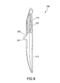
FIG. 9 is a side elevational of a third embodiment of the tool of FIGS. 1-5.
DESCRIPTION OF THE PREFERRED EMBODIMENTS
Referring to FIGS. 1-5, there is shown fencing tool 10 of the present invention. Tool 10 includes handles 11 and 12, jaws 13 and 14, and pin or member 15 for pivotably connecting the jaws and handles. Jaw 13 includes fence hammer 16. Jaw 14 includes fence staple starter and puller 17. Fence wire stretcher, splicer and cutter 18, 19 and 20 are construction features of the jaws. The foregoing fencing functionality features are known in commercially available fencing tools.
Handle 11 is formed with wedge 21 having elongated through hole or slot 22, for purposes hereinafter appearing.
Referring to FIGS. 6-8, there is shown wire strainer 50. Strainer 50 has frame 51, a pair of discs, each disc is formed with a plurality of ratcheted sprocket teeth 52 disposed on a rotatable spool or pin 53 so as to rotate from a first ratcheted position to a second ratcheted position. Spring lock or compression clip 54 holds the teeth and a wire loop end in a ratcheted position for purposes hereinafter appearing. Aligned through holes 55 enable an anchoring such as a length of a first wire loop end (not shown) to be threaded therethrough. A second wire loop end (not shown) is engaged by the teeth 52. The wire strainer is suspended between the first and second wire loop ends. The teeth when rotatably moved from the first to the second position strains the wire to the desired tension, as is well known in the fencing tool art. Strainer 50 may be one manufactured by Fi-Shock such as a 400-400 cc In Line Strainer with Comp Clip commercially available from Fishock.com or from Flemingoutdoors.com. Strainer 50 may also be the wire strainer as shown and described in US 2010/0051887, published Mar. 4, 2010 to Wooster et al. and in U.S. Pat. No. 6,820,862, granted Nov. 23, 2004 to Terzagi, which references are incorporated herein in their entireties by reference thereto. Like commercially available wire strainers are also within the contemplation of the present invention.
Referring specifically to FIGS. 7 and 8, there is shown the fencing tool 100 and wire strainer 50 combination aspect of the present invention. Tool 100 is constructed as previously described tool 10, including wedge 121, wedge edge 123 and through hole 122, with the following modifications. Outwardly extending member 110 is formed on the bottom surface 113 of handle 111. Member 110 is formed with a grip portion that provides thumb guard 150 and thumb receiving recess 151. In the foregoing manner of construction, with tool 100 in the closed disposition, the user grips handle 111 at grip the portion disposed between the wedge and the means for pivotably connecting the handles with the fingers engaging the adjacent handle in the fully closed position, and the tool 100 contactingly engages at least one of the teeth 52 in through hole or slot 122. The grip portion, thumb guard 150 and thumb receiving recess 151 protect the user's hand from slipping in the following operations. The user then proximately moves or downwardly rotates tool 100 as shown by arrow A so as to provide a leverage force and cause teeth 52 to rotate in the arrow A direction. The teeth on one disc rotate with certain teeth engaging the second wire loop end so that the fence wire strained. The method is repeated until the desired tension is provided to the wires. Only one of the pair of discs has ratchet teeth disc engaged by tool 100. The other disc and pars of ratchet teeth are concomitantly rotated with the engaged disc and teeth.
Referring specifically to FIG. 9, there is shown fencing tool 200 which has the fencing tool features of tools 10 and 200, with the following modifications. The embodiment 200 has wedge grip portion 210, and thumb guard 201, and is modified with a T-shaped section 202 disposed between the wedge 212 and the means for pivotally connection the handles. The T-section grip portion of FIG. 9 is shown and disclosed in commonly invented and owned U.S. Ser. No. 13/267,431, filed Oct. 6, 2011, now U.S. Pat. No. 8,291,274, which reference is incorporated herein its entirety by reference thereto. FIG. 9 shows the user's thumb abutting thumb guard 201 and thumb receiving recess 205, formed by T-section 202.
The tool of the present invention, when gripped particularly as shown in e.g. FIGS. 7-8, is particularly useful to have wedge edge inserted beneath the edge of a fence clip (not shown) to quickly remove the fence clip. Fence clips that may be readily removed in the foregoing manner are, by way of example, shown and disclosed in U.S. Pat. No. 6,050,549 to Foy (“Foy”), which reference is incorporated herein in its entirety by reference thereto. That is, the wedge edge may be inserted beneath the bottom edge of the Foy fence clip as shown in FIGS. 4-5 therein to unclip tabs 17 and 18, and thereby readily remove clip 10 from post 15.
While the present invention has been described with respect to certain specific embodiments, it should be understood that modifications and variations of the invention as afore-described might be constructed without departing from the spirit and scope of the invention as defined in the appended claims.

Claims (5)

What is claimed is:
1. In combination:
(a) a fencing tool comprising:
a first handle and a second handle, and first and second respective distally disposed jaws, and means for pivotably connecting the handles and respective jaws, so that the tool is disposed in an opened disposition and a closed disposition,
said first handle comprises a first surface and a second surface and being formed with a wedge extending from the second surface upwardly to the first surface terminating at a wedge edge, and having a through slot extending from the first surface to the second surface; and
(b) a fence wire strainer comprising a plurality of teeth, and means for ratchetedly rotatably mounting the teeth, so that the teeth are rotated from a first position to second position to strain the fence wire, with the strainer operably disposed with the fence wire; and
wherein the through slot engages at least one of the plurality of strainer teeth with the wedge first surface downwardly and facingly disposed to the fence wire strainer, and with the handles gripped in the closed disposition to provide a first operable position;
whereby with the handles gripped in the closed first operable position and the wedge edge distally disposed, the tool is moved in the proximate direction, and the teeth are rotated from the first position to the second position and strain the fence wire.
2. The combination of claim 1, wherein the first handle further comprises a grip portion disposed between the wedge and the means for pivotably connecting the handles and jaws in the first operable position with the wedge edge distally disposed.
3. The combination of claim 2, wherein the grip portion comprises a recess comprising a thumb receiving recess and further comprising an outwardly disposed member comprises a thumb guard.
4. The combination of claim 1, comprising in further combination:
(c) a fence clip fixedly disposed on a fence post;
wherein the wedge edge engages the fence clip with wedge second surface downwardly disposed;
whereby a leverage force is exerted to remove the fence clip from the fence post.
5. The combination of claim 1, said wire strainer further comprises means for mounting the wire strainer between facingly disposed looped ends of the fence wire.
US13/311,718 2006-07-26 2011-12-06 Fencing tool Active US8413555B2 (en)

Priority Applications (3)

Application Number Priority Date Filing Date Title
US13/311,718 US8413555B2 (en) 2006-07-26 2011-12-06 Fencing tool
US13/735,307 US8590863B1 (en) 2006-07-26 2013-01-07 Fencing tool
US13/736,131 US8776647B2 (en) 2006-07-26 2013-01-08 Fencing tool

Applications Claiming Priority (6)

Application Number Priority Date Filing Date Title
US11/493,682 US20080022815A1 (en) 2006-07-26 2006-07-26 Firefighter tool
US11/857,010 US8485074B2 (en) 2006-07-26 2007-09-18 Firefighter tool
US12/419,592 US8061239B2 (en) 2006-07-26 2009-04-07 Rescue tool
US12/751,204 US8065939B2 (en) 2006-07-26 2010-03-31 Rescue tool
US13/267,431 US8291794B2 (en) 2006-07-26 2011-10-06 Compact ergonomic rescue tool
US13/311,718 US8413555B2 (en) 2006-07-26 2011-12-06 Fencing tool

Related Parent Applications (1)

Application Number Title Priority Date Filing Date
US13/267,431 Continuation-In-Part US8291794B2 (en) 2006-07-26 2011-10-06 Compact ergonomic rescue tool

Related Child Applications (2)

Application Number Title Priority Date Filing Date
US13/735,307 Division US8590863B1 (en) 2006-07-26 2013-01-07 Fencing tool
US13/736,131 Continuation US8776647B2 (en) 2006-07-26 2013-01-08 Fencing tool

Publications (2)

Publication Number Publication Date
US20120073060A1 US20120073060A1 (en) 2012-03-29
US8413555B2 true US8413555B2 (en) 2013-04-09

Family

ID=45869147

Family Applications (3)

Application Number Title Priority Date Filing Date
US13/311,718 Active US8413555B2 (en) 2006-07-26 2011-12-06 Fencing tool
US13/735,307 Active US8590863B1 (en) 2006-07-26 2013-01-07 Fencing tool
US13/736,131 Active US8776647B2 (en) 2006-07-26 2013-01-08 Fencing tool

Family Applications After (2)

Application Number Title Priority Date Filing Date
US13/735,307 Active US8590863B1 (en) 2006-07-26 2013-01-07 Fencing tool
US13/736,131 Active US8776647B2 (en) 2006-07-26 2013-01-08 Fencing tool

Country Status (1)

Country Link
US (3) US8413555B2 (en)

Families Citing this family (3)

* Cited by examiner, † Cited by third party
Publication number Priority date Publication date Assignee Title
RU2623529C2 (en) * 2015-09-23 2017-06-27 Федеральное государственное бюджетное образовательное учреждение высшего профессионального образования "Саратовский государственный технический университет имени Гагарина Ю.А." (СГТУ имени Гагарина Ю.А.) Combined hand tool "torus"
USD826666S1 (en) * 2017-09-06 2018-08-28 Ruqian Zhang Masonry cutter hammer
CN109551533B (en) * 2018-12-17 2020-09-11 张保国 Novel multifunctional combined axe for fire fighting

Citations (11)

* Cited by examiner, † Cited by third party
Publication number Priority date Publication date Assignee Title
US1644352A (en) * 1926-10-28 1927-10-04 Edwin P Perrin Combination tool
US1949335A (en) * 1929-07-02 1934-02-27 Jacob T Settles Combination tool
US2875520A (en) * 1958-09-19 1959-03-03 Porter Inc H K One-hand cable cutter
US3599255A (en) * 1968-10-21 1971-08-17 Thomas P Carroll Sr Combination tool
US5303748A (en) 1987-01-02 1994-04-19 Haldemann Pol N Fencing tool
US5522290A (en) * 1994-04-18 1996-06-04 Visser; Steven C. Compliant pliers
US5586584A (en) 1987-01-02 1996-12-24 Haldemann; Pol N. Fencing tool and method of operation
US6050549A (en) 1998-02-03 2000-04-18 Foy; Bill D. Fence clip system
US6134994A (en) * 1998-05-15 2000-10-24 Facom Pliers with ergonomic handles
US20020063247A1 (en) 2000-11-27 2002-05-30 Andre Terzaghi Wire stainer
US20100051887A1 (en) 2008-08-27 2010-03-04 Robertson Engineering Limited Wire strainer

Family Cites Families (17)

* Cited by examiner, † Cited by third party
Publication number Priority date Publication date Assignee Title
US64662A (en) * 1867-05-14 Self and phillipp fermier
US836075A (en) * 1905-09-16 1906-11-13 Lewis Shanks Loudon Combination-tool.
US1396502A (en) * 1919-03-31 1921-11-08 Milton E Buck Wire-stretcher
US1739658A (en) * 1923-11-13 1929-12-17 James O Smith Wire-stretching tool
US2179438A (en) * 1939-06-02 1939-11-07 Stewart Burry Willard Wire stretcher
US3874638A (en) * 1973-09-27 1975-04-01 Howard Langlie Wire or rope tightener
USD281216S (en) * 1982-12-03 1985-11-05 Cutliff Jr Norman J Fireman's tool
USD311313S (en) * 1988-09-12 1990-10-16 Sloan Valve Company Wrench
US4995128A (en) * 1990-01-22 1991-02-26 Montgomery Robert D Electrician's combination tool
US5339507A (en) * 1991-11-13 1994-08-23 Cox Rick L Window removal system
US5351402A (en) * 1993-10-26 1994-10-04 Mansfield Leonard L Hard nut kernel extractor
US5695147A (en) * 1994-10-25 1997-12-09 Zimmerman; Harry I. Length controller for flexible line and method of use
US6477747B1 (en) * 2000-11-03 2002-11-12 Terry Flagg Load binder with locking structure
US20060156474A1 (en) 2005-01-14 2006-07-20 Chris Gillingham Multi-purpose rescue tool
US20090056509A1 (en) * 2007-07-11 2009-03-05 Anderson Mark C Pliers made of an in situ composite of bulk-solidifying amorphous alloy
US7845254B2 (en) * 2008-02-23 2010-12-07 Mike Lionel Firefighter pocket tool
US20100122419A1 (en) * 2008-11-14 2010-05-20 Amber Zupancic-Albin Multi-Function Tool for Healthcare Professionals

Patent Citations (12)

* Cited by examiner, † Cited by third party
Publication number Priority date Publication date Assignee Title
US1644352A (en) * 1926-10-28 1927-10-04 Edwin P Perrin Combination tool
US1949335A (en) * 1929-07-02 1934-02-27 Jacob T Settles Combination tool
US2875520A (en) * 1958-09-19 1959-03-03 Porter Inc H K One-hand cable cutter
US3599255A (en) * 1968-10-21 1971-08-17 Thomas P Carroll Sr Combination tool
US5303748A (en) 1987-01-02 1994-04-19 Haldemann Pol N Fencing tool
US5586584A (en) 1987-01-02 1996-12-24 Haldemann; Pol N. Fencing tool and method of operation
US5522290A (en) * 1994-04-18 1996-06-04 Visser; Steven C. Compliant pliers
US6050549A (en) 1998-02-03 2000-04-18 Foy; Bill D. Fence clip system
US6134994A (en) * 1998-05-15 2000-10-24 Facom Pliers with ergonomic handles
US20020063247A1 (en) 2000-11-27 2002-05-30 Andre Terzaghi Wire stainer
US6820862B2 (en) 2000-11-27 2004-11-23 Tru-Test Limited Wire strainer
US20100051887A1 (en) 2008-08-27 2010-03-04 Robertson Engineering Limited Wire strainer

Also Published As

Publication number Publication date
US8776647B2 (en) 2014-07-15
US20130227793A1 (en) 2013-09-05
US20130299619A1 (en) 2013-11-14
US20120073060A1 (en) 2012-03-29
US8590863B1 (en) 2013-11-26

Similar Documents

Publication Publication Date Title
US4539873A (en) Pryer-plier tool
US8429948B1 (en) Twisting device for a plurality of electrical wires and method of use thereof
US8590863B1 (en) Fencing tool
CA2513659A1 (en) Adjustable hair holding device
US6561556B2 (en) Closure clamp
AU2019100416B4 (en) Wire strainers
US20080178707A1 (en) Pliers for cutting and holding straps and the like
US5586584A (en) Fencing tool and method of operation
US7272994B1 (en) Bolt grasping device
US3934286A (en) Hand tool
US5303748A (en) Fencing tool
US20040035255A1 (en) Nailer's pliers
US4921216A (en) Staple remover
WO2006002442A1 (en) Wire tying implement
US20050097758A1 (en) Tool for cutting cable ties leaving a round end
CA2295345C (en) Connecting device for the cables around a log bundle
CN112498791B (en) Iron wire binding tool and iron wire binding method
TWM555785U (en) Pliers hanging plate
AU2019100320B4 (en) Wire strainers
US6145811A (en) Staple remover having planar pressing surfaces and staple receiving locking notches
US8479751B2 (en) Plier-type power flosser
CN112689696A (en) Fence device and fence technology
GB2322325A (en) Multi-purpose pliers tool
US6349923B1 (en) Staple remover
US1551035A (en) Wrecking bar and wire stretcher

Legal Events

Date Code Title Description
FEPP Fee payment procedure

Free format text: PETITION RELATED TO MAINTENANCE FEES GRANTED (ORIGINAL EVENT CODE: PTGR); ENTITY STATUS OF PATENT OWNER: SMALL ENTITY

STCF Information on status: patent grant

Free format text: PATENTED CASE

AS Assignment

Owner name: CHANNELLOCK, INC., DELAWARE

Free format text: ASSIGNMENT OF ASSIGNORS INTEREST;ASSIGNOR:FARRELL, TERRY C.;REEL/FRAME:030866/0859

Effective date: 20130712

FPAY Fee payment

Year of fee payment: 4

MAFP Maintenance fee payment

Free format text: PAYMENT OF MAINTENANCE FEE, 8TH YR, SMALL ENTITY (ORIGINAL EVENT CODE: M2552); ENTITY STATUS OF PATENT OWNER: SMALL ENTITY

Year of fee payment: 8