US8405724B2 - Automobile camera module and method to indicate moving guide line - Google Patents
Automobile camera module and method to indicate moving guide line Download PDFInfo
- Publication number
- US8405724B2 US8405724B2 US12/461,166 US46116609A US8405724B2 US 8405724 B2 US8405724 B2 US 8405724B2 US 46116609 A US46116609 A US 46116609A US 8405724 B2 US8405724 B2 US 8405724B2
- Authority
- US
- United States
- Prior art keywords
- image
- guide line
- steering angle
- vehicle
- camera module
- Prior art date
- Legal status (The legal status is an assumption and is not a legal conclusion. Google has not performed a legal analysis and makes no representation as to the accuracy of the status listed.)
- Expired - Fee Related, expires
Links
Images


Classifications
-
- H—ELECTRICITY
- H04—ELECTRIC COMMUNICATION TECHNIQUE
- H04N—PICTORIAL COMMUNICATION, e.g. TELEVISION
- H04N23/00—Cameras or camera modules comprising electronic image sensors; Control thereof
- H04N23/60—Control of cameras or camera modules
-
- B—PERFORMING OPERATIONS; TRANSPORTING
- B62—LAND VEHICLES FOR TRAVELLING OTHERWISE THAN ON RAILS
- B62D—MOTOR VEHICLES; TRAILERS
- B62D15/00—Steering not otherwise provided for
- B62D15/02—Steering position indicators ; Steering position determination; Steering aids
- B62D15/027—Parking aids, e.g. instruction means
- B62D15/0275—Parking aids, e.g. instruction means by overlaying a vehicle path based on present steering angle over an image without processing that image
-
- B—PERFORMING OPERATIONS; TRANSPORTING
- B62—LAND VEHICLES FOR TRAVELLING OTHERWISE THAN ON RAILS
- B62D—MOTOR VEHICLES; TRAILERS
- B62D15/00—Steering not otherwise provided for
- B62D15/02—Steering position indicators ; Steering position determination; Steering aids
- B62D15/029—Steering assistants using warnings or proposing actions to the driver without influencing the steering system
- B62D15/0295—Steering assistants using warnings or proposing actions to the driver without influencing the steering system by overlaying a vehicle path based on present steering angle over an image without processing that image
-
- H—ELECTRICITY
- H04—ELECTRIC COMMUNICATION TECHNIQUE
- H04N—PICTORIAL COMMUNICATION, e.g. TELEVISION
- H04N23/00—Cameras or camera modules comprising electronic image sensors; Control thereof
- H04N23/57—Mechanical or electrical details of cameras or camera modules specially adapted for being embedded in other devices
Definitions
- the present invention relates to a camera module mounted on an vehicle, and a method to indicate a moving guide line using the same; and, more particularly, to an automobile camera module and a method to indicate a moving guide line using the same, which can display a rear photography image and a guile line image stored divided according to a steering angle of a vehicle's handle in an overlay scheme when the vehicle moves in reverse, and thus provide a guide line for the actual rear situation, so that the vehicle's driver can easily back-in park.
- a vehicle has been recently developed to provide traveling performance safety and various conveniences.
- a number of sensors are provided inside or outside of the chassis so that it is possible to sense the external surrounding environment even in the vehicle.
- parking assistant systems have been provided to prevent an accidental collision that may occur during traveling, in which a camera is mounted on the front or the rear of the vehicle to display an external image on a monitor when the vehicle enters a side street, or moves in reverse for parking.
- side mirrors and room mirrors mounted inside or outside of the vehicle are mostly used at the time of back-in parking.
- a luxury vehicle is provided with a function for displaying an image photographed by a camera together with a vehicle traveling trace, thereby allowing the driver to estimate a direction in which the vehicle moves, which helps an inexperienced driver or an aged driver back-in park easily.
- a scheme for providing a rear image together with the vehicle traveling trace has a problem in that because the trace is displayed by different angles of view changed depending on a location where the camera is mounted, the vehicle traveling trace displayed on the photographed image should be newly set through a CPU every time angles of view are changed.
- an estimated traveling trace with which the image photographed by the camera mounted on the vehicle is additionally provided is mostly displayed to have a linear shape that gets narrow toward the rear side, it is difficult to display a traveling trace of the actual vehicle that backward-moves at various angles.
- the vehicle is required to be equipped with a separate trace generation device, and a separate CPU.
- the separate trace generation device generates a traveling trace including calculated traveling ranges
- the separate CPU is used to overlap the generated traveling trace with an image photographed by the camera and output the overlapped image. Therefore, there are problems such as complex device configuration, and increase in manufacturing costs.
- the present invention has been invented in order to overcome the above-described problems and it is, therefore, an object of the present invention to provide an automobile camera module and a method to indicate a moving guide line, in which an image sensor itself overlaps an image photographed by a camera with a guide line image divided and stored for each steering angle of a vehicle's handle in a memory, and displays a rear image and a guide line image changed according to the steering angle of the handle in an overlay scheme on a monitor mounted inside of the vehicle, thereby easily recognizing rear situation of the vehicle.
- another object of the present invention is to provide an automobile camera module and a method to indicate a moving guide line using the same, which pre-stores guide line images that may be changed depending on an image, photographed according to angles of view of a camera mounted on the vehicle, displays the stored guide line image and the photographed image in an overlay scheme, thereby providing a rear traveling trace of the vehicle only through overlapping of the preset guide line image with the photographed image without a separate image generation device.
- an automobile camera module including: a memory for storing guide line images for vehicle traveling traces divided according to a steering angle of the vehicle's handle; an image sensor for photographing a front image or a rear image, and generating an image signal for an image obtained by overlapping the guide line image stored in the memory with the photographed image; a controller (CAN MCU) for receiving steering angle information of the vehicle's handle, extracting a guide line image corresponding to the steering angle from the guide line images, and controlling the image sensor to perform image overlap; and an image output amp for converting a signal of the image overlapped in the image sensor into an output signal, and transmitting the converted signal to an image display unit through a serial bus network.
- a controller CAN MCU
- the automobile camera module may further include a communication unit for transmitting and receiving a steering signal of the vehicle to/from the controller by recognizing the steering angle of the handle attached to the vehicle.
- the communication unit may be connected in a communication scheme of a Controller Area Network (CAN) or an RS232.
- CAN Controller Area Network
- RS232 RS232
- the memory may be composed of a flash memory, and stores guide line images having the vehicle's traveling trace displayed thereon.
- the guide line images are divided and stored for each of right and left steering angles of the vehicle's handle in the memory.
- the guide line images have the maximum 200 guide line images according to the steering angle of the handle stored therein in the form of bitmap.
- a number of the guide line images stored in the memory are selected by steering angle information of the handle that the controller receives, and a selected guide line image is overlaid and outputted with the image photographed in the image sensor.
- the image sensor photographs an external image of the front or the rear of the vehicle through a lens unit mounted on the camera module, converts the photographed image into an image signal, and then outputs the converted signal to the image display unit through the image output amp.
- the image sensor itself overlaps the photographed image with a guide line image selected according to a steering angle of the handle through the controller, and converts the overlapped image into an image signal through the image display unit.
- the controller receives steering angle information of the handle received through the communication unit, extracts a guide line image for a corresponding steering angle, so that the controller can control the image sensor to perform overlap and recognize the front rotation angle with respect to the central axis of the vehicle.
- the controller recognizes a current front rotation angle of the vehicle, thereby setting the front rotation angle as a reference axis, and then receives steering angles of right-rotated handle and left-rotated handle based on the current reference axis through the communication unit.
- the image output amp is electrically connected to the image sensor and the image display unit, and converts an image signal converted by the image sensor into an external output signal of National Television System Committee (NTSC) or Phase Alternating Line (PAL) scheme to transmit the converted image signal to the image display unit.
- NSC National Television System Committee
- PAL Phase Alternating Line
- a method to indicate a moving guide line including the steps of: photographing an external image of a vehicle through a camera module mounted on the front or the rear of the vehicle; receiving, by a controller, a steering signal for a steering angle of the vehicle's handle through a communication unit connected to the camera module; selecting a guide line image corresponding to the steering signal from a plurality of guide line images, stored in a memory within the camera module, based on steering angle information of the vehicle's handle received to the controller; transmitting the guide line image selected by the controller to an image sensor within the camera module, and then overlapping the transmitted guide line image with the external image photographed by the image sensor; and converting the image, obtained by overlapping the external image with the guide line image, into an image signal, and then outputting the image signal to the image display unit connected to the camera module, through an image output amp connected to the image sensor.
- the controller receives a current front rotation angle of the vehicle through the communication unit, and sets the front rotation angle as a reference axis, and then receives information about a steering angle of the vehicle's handle based on the set reference axis from the communication unit.
- the image sensor overlaps a guide line image corresponding to the steering angle information of the vehicle's handle selected from the guild line images stored in the memory with an external image based on one-to-one correspondence in an image overlapping unit of the image sensor, and transmits the overlapped image to an outside through a video encoder.
- the external image photographed by the camera module is subjected to brightness and color adjustment processes through an image processor before being overlapped with the guide line image, and the guide line image is subjected to an image correction process for correcting an image according to surrounding brightness through a lens compensating unit before being selected, so that the external image is finally overlapped with the selected guide line image.
- the image signal outputted through the image output amp is converted into an external output signal of an NTSC or a PAL scheme, thereby outputting an image through an external monitor.
- a corresponding guide line image can be selected according to the steering angle of the handle by matching a multiple of information to a specific value of the guide line image stored in the memory, wherein the information is calculated by dividing a sum of a greatest right steering angle and a greatest left steering angle by the number of the guide line images.
- FIG. 1 is a block diagram illustrating an automobile camera module in accordance with the embodiment of the present invention
- FIG. 2 is a view showing that the steering angles are respectively matched to guide line images stored in the memory of the camera module in accordance with the embodiment of the present invention.
- FIG. 3 is a block diagram of an image sensor applied to a camera module in accordance with an embodiment of the present invention.
- FIG. 1 is a block diagram illustrating an automobile camera module in accordance with the embodiment of the present invention.
- the automobile camera module 100 may include a memory 110 , an image sensor 120 , and an image output amp 130 .
- the memory 110 stores a plurality of guide lines based on a steering angle of a vehicle's handle, and the image sensor 120 photographs an external image and then overlaps the photographed image with the guide line image divided according to a steering angle stored in the memory 110 .
- the image output amp 130 transmits an image having a guide line image overlapped therewith to the outside.
- the automobile camera module 100 selects a guide line image, which is to be overlapped by the image sensor 120 , according to a steering angle of the handle, and it further includes a controller 140 for controlling the image sensor 120 to perform one-to-one overlap.
- the memory 110 which is built in the automobile camera module 100 , transmits information stored in the memory 110 to the image sensor 120 .
- the memory 110 may include a flash memory, and stores guide line images having various shapes for rear traveling traces divided according to a steering angle of the vehicle's handle.
- the guide line image may be stored by dividing the rear traveling trace of the vehicle for each of representative steering angles with reference to a rear image of the vehicle.
- the guide line image may have a total of 200 guide line images.
- the 200 guide line images may be stored in the form of bitmap.
- the total of 200 guide line images are divided into 100 guide line images for each of the right and left steering angles based on a location at which the vehicle's wheel is in an original position as 0°.
- the image sensor 120 which can transmit and receive data to/from the memory 110 photographs a front image or mostly a rear image.
- the image sensor 120 overlaps the specific guide line image received from the memory 110 with the rear photography image by itself, and outputs the overlapped image.
- the guide line image to be overlapped with the rear photography image by the image sensor 120 corresponds to a specific guide line image selected according to a steering angle of the vehicle.
- a detailed description will be given of a method for selecting a guide line image according to a steering angle of the handle.
- the image sensor 120 converts a rear image, photographed through a lens unit (not shown) mounted in the automobile camera module 100 , into an image signal, and transmits the converted image signal to an image display unit 200 , which includes an external monitor, through the image output amp 130 electrically connected to the image sensor 120 .
- the image sensor 120 receives a guide line image, which is to be overlapped with the photographed rear image, from the memory 110 , thereby performing image overlap by mixture of color information (RGB) for the images.
- RGB color information
- the guide line image to be transmitted to the image sensor 120 is selected according to a steering angle of the handle by the controller 140 , and the guide line selected by the controller 140 is allowed to be overlapped with the rear image in the image sensor 120 .
- the controller 140 may include a CAN MCU, and the controller 140 and the image sensor 120 are interconnected to transmit and receive data between them through I2C communication.
- the controller 140 is connected to a communication unit 210 through the communication scheme of the automobile camera module 100 , a CAN, and so on, and thus receives a control signal which the controller 140 needs, i.e. information for steering angles of the vehicle's handle.
- the communication unit 210 may use a communication scheme of CAN 2.0 or an RS232 protocol, and mostly use the CAN communication scheme capable of continuous data transmission and reception because it is required to transmit and receive data for image processing.
- the CAN communication refers to a communication scheme, in which when a plurality of sensors or motors are required to be incorporated in a system including a vehicle, communication information of peripheral devices is transferred to all nodes within the network by using a unique identifier of each of the peripheral devices, and then respective nodes determine whether or not to process corresponding information based on the identifier, thereby allowing data to be seamlessly transmitted and received.
- the information of the steering angle of the handle received in the communication unit 210 is received to the controller 140 provided in the automobile camera module 100 though the CAN, and the controller 140 extracts the guide line image for a corresponding steering angle from the memory 110 .
- the controller 140 controls the image information photographed by the image sensor 120 to be overlapped with the guide line image on the basis of one-to-one correspondence.
- the controller 140 recognizes the steering angle information of the handle, received through the communication unit 210 , as well as a front rotation angle with respect to a central axis of the vehicle, thereby setting the front rotation angle as a reference axis.
- the controller 140 allows a corresponding guide line image estimated according to right and left steering angles of the vehicle's handle to be extracted from the memory 110 by taking the front rotation angle as the reference axis based on the current vehicle's central axis, and allows the corresponding guide line image to be overlapped with the rear photography image, so that the overlapped image can be displayed.
- the image output amp 130 converts an image obtained by overlapping the rear photography image with the guide line image in the image sensor 120 (hereinafter, referred to as “guide line displayed image”) into an external output signal, and then transmits the converted output signal to the external monitor.
- the image output amp 130 converts the guide line displayed image into an external output signal of an NTSC (Nation Television System Committee) or a PAL (Phase Alternating Line) scheme to transmit the resultant signal to the external monitor.
- NTSC Nation Television System Committee
- PAL Phase Alternating Line
- the automobile camera module 100 having the above-described same construction is equipped with the image sensor 120 and the memory 110 , so that the image sensor 120 itself overlaps the external image, photographed by the image sensor 120 , with the guide line image which the memory 110 stores for each steering angle of the handle, so as to display the guide line displayed image on the external monitor.
- FIG. 2 is a view showing that the steering angles are respectively matched to guide line images stored in the memory of the camera module in accordance with the embodiment of the present invention.
- FIG. 2 shows guide line images of the memory 110 , which may be selected according to an actual steering angles when the guide line image is overlapped with an image photographed by the camera module.
- the memory 110 stores about 200 guide line images divided for each of right and left steering angles on the basis of handle's steering angle 0°.
- the controller 140 within the automobile camera module 100 receives information about handle's steering angle based on the reference axis of a current vehicle through the communication unit 210 . Then, a corresponding guide line image is selected for handle's steering angle through the information about the steering angle received to the controller 140 .
- the controller 140 transmits information of the guide line image selected for the handle's steering angle to the image sensor 120 through I2C communication. Then, the image sensor 120 selects and calls the guide line image for a corresponding steering angle from the memory 110 by a steering signal.
- the memory 110 transmits information about the guide line image called in the image sensor 120 , through an SPI communication, and the image sensor 120 overlaps the photographed image with the called guide line image by combination of pixel information for the images.
- ⁇ LMax ⁇ L1 , ⁇ L2 , . . . , ⁇ LMax-1 , ⁇ LMax ⁇
- ⁇ RMax ⁇ R1 , ⁇ R2 , . . . ⁇ RMax-1 , ⁇ RMax ⁇ .
- a guide line image corresponding to an actual steering angle can be selected from the guide line images for each of right and left steering angles stored in the memory 110 , by multiplying each steering angle to a result value (a) defined as equation (1) below.
- the guide line image that may be selected by equation (1) is selected as shown in FIG. 2 .
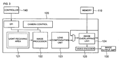
- FIG. 3 is a block diagram of an image sensor applied to a camera module in accordance with an embodiment of the present invention.
- the image sensor 120 includes a light-receiving area 121 for receiving external image information, an image processor 122 for adjusting brightness and colors of images, a lens compensating unit 123 for compensating for brightness around the lens, and an image overlapping unit 124 for performing overlap of the guide line images based on the pixel information of the light-receiving area 121 .
- the light-receiving area 121 may have a VGA 640 ⁇ 480 resolution in consideration of the size and resolution of an external monitor. Brightness and colors for the external image stored in the light-receiving area 121 may be adjusted through the image processor 122 .
- a lens unit (not shown) onto which external light is incident allows the image to be photographed clearly by compensating the brightness of the light incident through the lens unit by means of a lens compensating unit 123 .
- a corresponding guide line image according to a steering angle is extracted from the memory 110 by recognition of steering angle information of the controller 140 .
- the image overlapping unit 124 overlaps the external image photographed by the light-receiving area 121 with the corresponding guide line image so that pixel information of the external image is matched to that of the guide line image, respectively on the basis of one-to-one correspondence.
- the guide line displayed image is transmitted to the image output amp 130 through the video encoder 125 .
- the image output amp 130 converts the transmitted image into an output signal to display the converted signal on the external monitor.
- RGB information of i th pixel in image information of 640 ⁇ 480 pixels generated through the light-receiving area 121 is overlapped with color information of i th guide line image stored in the memory 110 .
- R, G, B data of i th image information are defined as R i image , G i image , B i image , respectively
- R, G, B data of color information of i th guide line image are defined as R i line , G i line , B i line , respectively
- the guide line image is overlapped with the photographed image by combination of color information through equation (2) below.
- R i (1 ⁇ t ) R i image +tR i line
- G i (1 ⁇ t ) G i image +tG i line
- B i (1 ⁇ t ) B i image +tB i line
- ‘t’ ranges between 0 and 1
- ‘t’ determines transparency of the guide line images. Further, colors of the guide line images become deep as ‘t’ is increased, whereas colors of the guide line image become light as ‘t’ is decreased. That is, the guide line fails to be displayed on the image when ‘t’ has a value of 0.
- a moving guide line according to a rear traveling trace can be displayed by information received through the camera module having the above-described construction, and thus an external image of the vehicle is photographed by the automobile camera module 100 mounted on the front or mostly rear of the vehicle. Then, the image photographed by the camera module is subjected to brightness and color adjustment processes, and is converted into an image signal by the image sensor.
- the automobile camera module 100 receives steering angle information of vehicle's handle through the communication unit 210 , which includes a CAN, and so on.
- the steering angle information of vehicle's handle is received to the controller 140 within the automobile camera module 100 through the communication unit 210 .
- a guide line image corresponding to the received steering angle is selected from among the guide line images stored in the memory 110 .
- the image overlapping unit 124 of the image sensor 120 transmits the guide line image selected by the controller 140 to the image sensor 120 within the camera module, and then overlaps the transmitted image with the external image based on combination of color information of R, G, and B.
- the image output amp converts the image overlapped by the image overlapping unit 124 into an output signal capable of outputting an image, and then transmits the converted image to the external device, so that the guide line displayed image can be displayed on the external monitor.
- the controller 140 is composed of a CAN MCU connected to perform communication through a CAN, and the controller 140 receives a current front rotation angle of the vehicle through the communication unit 210 , and then sets the received current front rotation angle as a reference axis. Then, the controller 140 receives information about a steering angle of vehicle's handle based on the reference axis through the communication unit 210 .
- a point at which central axis of the vehicle is currently located is set as a reference axis, and a steering angle of the vehicle's handle is received so as to provide a rear photography image with a moving guide line in an overlay scheme.
- the image overlapping unit 124 of the image sensor 120 overlaps an external image with a guide line image corresponding to the steering angle of vehicle's handle among the guide line images stored in the memory 110 based on one-to-one correspondence of their pixel information, and then transmits the overlapped image to an outside through the video encoder 125 and the image output amp 130 .
- a guide line image for each of steering angles of the vehicle's handle is overlapped with an image photographed by a camera in the image sensor itself, and then overlapped image is outputted to an external monitor, so that a system can be simply constructed only with a camera module so as to perform image overlap and image output, which results in reduction of manufacturing costs. Further, an area occupied by the camera module can be minimized, which results in easy mounting and reduction in mounting costs.
- the automobile camera module and the method to indicate a moving guide line in accordance with the present invention have advantages in that an angle of view of the camera module can be simply adjusted according to the mounting location.
Landscapes
- Engineering & Computer Science (AREA)
- Chemical & Material Sciences (AREA)
- Combustion & Propulsion (AREA)
- Transportation (AREA)
- Mechanical Engineering (AREA)
- Multimedia (AREA)
- Signal Processing (AREA)
- Closed-Circuit Television Systems (AREA)
- Studio Devices (AREA)
- Image Processing (AREA)
Abstract
Description
R i=(1−t)R i image +tR i line
G i=(1−t)G i image +tG i line
B i=(1−t)B i image +tB i line (2)
Claims (14)
Applications Claiming Priority (2)
| Application Number | Priority Date | Filing Date | Title |
|---|---|---|---|
| KR10-2009-0048589 | 2009-06-02 | ||
| KR1020090048589A KR101023334B1 (en) | 2009-06-02 | 2009-06-02 | Car Camera Module and Parking Guide Display Method Using the Same |
Publications (2)
| Publication Number | Publication Date |
|---|---|
| US20100302368A1 US20100302368A1 (en) | 2010-12-02 |
| US8405724B2 true US8405724B2 (en) | 2013-03-26 |
Family
ID=43219771
Family Applications (1)
| Application Number | Title | Priority Date | Filing Date |
|---|---|---|---|
| US12/461,166 Expired - Fee Related US8405724B2 (en) | 2009-06-02 | 2009-08-03 | Automobile camera module and method to indicate moving guide line |
Country Status (2)
| Country | Link |
|---|---|
| US (1) | US8405724B2 (en) |
| KR (1) | KR101023334B1 (en) |
Cited By (2)
| Publication number | Priority date | Publication date | Assignee | Title |
|---|---|---|---|---|
| US10019841B2 (en) | 2011-05-18 | 2018-07-10 | Magna Electronics Inc. | Driver assistance systems for vehicle |
| US11256934B2 (en) | 2017-12-07 | 2022-02-22 | Samsung Electronics Co., Ltd. | Vehicle and method for controlling same |
Families Citing this family (9)
| Publication number | Priority date | Publication date | Assignee | Title |
|---|---|---|---|---|
| US20120173091A1 (en) * | 2010-12-29 | 2012-07-05 | Caterpillar Inc. | Monitoring system for a mobile machine |
| CN102529844A (en) * | 2010-12-31 | 2012-07-04 | 深圳市豪恩汽车电子装备有限公司 | Backing auxiliary method, backing auxiliary system and automobile |
| KR101288069B1 (en) | 2011-11-14 | 2013-07-18 | 현대모비스 주식회사 | Parking assistance system using projector and method thereof |
| KR101353090B1 (en) * | 2012-05-30 | 2014-01-20 | 삼성전기주식회사 | An on screen display device and an on screen displaing method |
| KR101387189B1 (en) | 2012-05-30 | 2014-04-29 | 삼성전기주식회사 | A display device of assistance information for driving and a display method of assistance information for driving |
| KR101489272B1 (en) | 2014-03-17 | 2015-02-06 | ㈜베이다스 | Synchronization composition system for the plural image including backup function of signal generation |
| KR101816572B1 (en) * | 2016-12-28 | 2018-02-21 | 엘지전자 주식회사 | Camera apparatus for vehicle and vehicle |
| KR102246660B1 (en) * | 2020-06-19 | 2021-05-03 | 현대모비스 주식회사 | Rear camera system |
| DE102021110388B4 (en) * | 2021-04-23 | 2023-04-06 | Sick Ag | Brightness and color correction of image data from a line scan camera |
Citations (12)
| Publication number | Priority date | Publication date | Assignee | Title |
|---|---|---|---|---|
| JP2000078566A (en) | 1998-08-31 | 2000-03-14 | Aisin Seiki Co Ltd | Parking assistance device |
| JP2000313292A (en) | 1999-05-06 | 2000-11-14 | Toyota Autom Loom Works Ltd | Steering assisting device at retreating |
| KR200345814Y1 (en) | 2003-12-30 | 2004-03-27 | 주식회사 현대오토넷 | Rear view system for vehicles |
| KR20040031576A (en) | 2002-10-07 | 2004-04-13 | 야자키 소교 가부시키가이샤 | Parking assisting device |
| JP2004262449A (en) | 2004-04-12 | 2004-09-24 | Aisin Seiki Co Ltd | Parking assistance device |
| US20050143895A1 (en) * | 2003-12-25 | 2005-06-30 | Tetuya Kato | Active drive assist system |
| US6999002B2 (en) * | 2002-04-05 | 2006-02-14 | Matsushita Electric Industrial Co., Ltd. | Parking operating assisting system |
| US20060072011A1 (en) * | 2004-08-04 | 2006-04-06 | Autonetworks Technologies, Ltd. | Vehicle peripheral visual confirmation apparatus |
| KR20070116199A (en) | 2007-03-19 | 2007-12-07 | 유승현 | Reverse Parking Image Assistance System of Vehicle and Its Control Method |
| US20080122654A1 (en) * | 2006-11-28 | 2008-05-29 | Aisin Aw Co., Ltd. | Parking support method and parking support apparatus |
| US20080266389A1 (en) * | 2000-03-02 | 2008-10-30 | Donnelly Corporation | Vehicular video mirror system |
| US20100079582A1 (en) * | 2008-10-01 | 2010-04-01 | Dunsmore Clay A | Method and System for Capturing and Using Automatic Focus Information |
-
2009
- 2009-06-02 KR KR1020090048589A patent/KR101023334B1/en not_active Expired - Fee Related
- 2009-08-03 US US12/461,166 patent/US8405724B2/en not_active Expired - Fee Related
Patent Citations (12)
| Publication number | Priority date | Publication date | Assignee | Title |
|---|---|---|---|---|
| JP2000078566A (en) | 1998-08-31 | 2000-03-14 | Aisin Seiki Co Ltd | Parking assistance device |
| JP2000313292A (en) | 1999-05-06 | 2000-11-14 | Toyota Autom Loom Works Ltd | Steering assisting device at retreating |
| US20080266389A1 (en) * | 2000-03-02 | 2008-10-30 | Donnelly Corporation | Vehicular video mirror system |
| US6999002B2 (en) * | 2002-04-05 | 2006-02-14 | Matsushita Electric Industrial Co., Ltd. | Parking operating assisting system |
| KR20040031576A (en) | 2002-10-07 | 2004-04-13 | 야자키 소교 가부시키가이샤 | Parking assisting device |
| US20050143895A1 (en) * | 2003-12-25 | 2005-06-30 | Tetuya Kato | Active drive assist system |
| KR200345814Y1 (en) | 2003-12-30 | 2004-03-27 | 주식회사 현대오토넷 | Rear view system for vehicles |
| JP2004262449A (en) | 2004-04-12 | 2004-09-24 | Aisin Seiki Co Ltd | Parking assistance device |
| US20060072011A1 (en) * | 2004-08-04 | 2006-04-06 | Autonetworks Technologies, Ltd. | Vehicle peripheral visual confirmation apparatus |
| US20080122654A1 (en) * | 2006-11-28 | 2008-05-29 | Aisin Aw Co., Ltd. | Parking support method and parking support apparatus |
| KR20070116199A (en) | 2007-03-19 | 2007-12-07 | 유승현 | Reverse Parking Image Assistance System of Vehicle and Its Control Method |
| US20100079582A1 (en) * | 2008-10-01 | 2010-04-01 | Dunsmore Clay A | Method and System for Capturing and Using Automatic Focus Information |
Non-Patent Citations (2)
| Title |
|---|
| Korean Notice of Allowance mailed Feb. 23, 2011 issued in corresponding Korean Patent Application No. 10-2009-0048589. |
| Korean Office Action mailed Sep. 17, 2010 issued in corresponding Korean Patent Application No. 10-2009-0048589. |
Cited By (6)
| Publication number | Priority date | Publication date | Assignee | Title |
|---|---|---|---|---|
| US10019841B2 (en) | 2011-05-18 | 2018-07-10 | Magna Electronics Inc. | Driver assistance systems for vehicle |
| US10169926B2 (en) | 2011-05-18 | 2019-01-01 | Magna Electronics Inc. | Driver assistance system for vehicle |
| US10559134B2 (en) | 2011-05-18 | 2020-02-11 | Magna Electronics Inc. | Driver backup assistance system for vehicle |
| US10957114B2 (en) | 2011-05-18 | 2021-03-23 | Magna Electronics Inc. | Vehicular backup assistance system |
| US11842450B2 (en) | 2011-05-18 | 2023-12-12 | Magna Electronics Inc. | Vehicular backing up assistance system |
| US11256934B2 (en) | 2017-12-07 | 2022-02-22 | Samsung Electronics Co., Ltd. | Vehicle and method for controlling same |
Also Published As
| Publication number | Publication date |
|---|---|
| KR101023334B1 (en) | 2011-03-22 |
| KR20100129965A (en) | 2010-12-10 |
| US20100302368A1 (en) | 2010-12-02 |
Similar Documents
| Publication | Publication Date | Title |
|---|---|---|
| US8405724B2 (en) | Automobile camera module and method to indicate moving guide line | |
| US8514282B2 (en) | Vehicle periphery display device and method for vehicle periphery image | |
| KR102647268B1 (en) | Image pickup device and electronic apparatus | |
| JP5194679B2 (en) | Vehicle periphery monitoring device and video display method | |
| US9707890B2 (en) | Automobile camera module, method of driving the same and method of guiding parking | |
| US10110820B2 (en) | Imaging device, imaging system, and imaging method | |
| JP5321711B2 (en) | Vehicle periphery monitoring device and video display method | |
| US12214733B2 (en) | Camera unit installing method, moving device, image processing system, image processing method, and storage medium | |
| US10875452B2 (en) | Driving assistance device and driving assistance method | |
| JP2008077628A (en) | Image processor and vehicle surrounding visual field support device and method | |
| WO2010070920A1 (en) | Device for generating image of surroundings of vehicle | |
| JP6471522B2 (en) | Camera parameter adjustment device | |
| KR20130037274A (en) | An apparatus and method for assisting parking using the multi-view cameras | |
| US12406344B2 (en) | Image processing system, image processing method, and storage medium | |
| US10455159B2 (en) | Imaging setting changing apparatus, imaging system, and imaging setting changing method | |
| KR101393918B1 (en) | A vehicle around view monitorring system | |
| JP2024063155A (en) | MOBILE BODY, IMAGE PROCESSING METHOD, AND COMPUTER PROGRAM | |
| US20240259671A1 (en) | Image processing system, movable apparatus, image processing method, and storage medium | |
| KR100899892B1 (en) | How to display car camera device and guide line | |
| JP5195776B2 (en) | Vehicle periphery monitoring device | |
| JP5305750B2 (en) | Vehicle periphery display device and display method thereof | |
| JP2010288199A (en) | In-vehicle monitor system, parking support apparatus using the in-vehicle monitor system, and color adjustment method for in-vehicle monitor system | |
| KR20100019605A (en) | Rear camera display system | |
| WO2017169087A1 (en) | Electric circuit for electronic mirror | |
| JP2005029067A (en) | Vehicle night vision system |
Legal Events
| Date | Code | Title | Description |
|---|---|---|---|
| AS | Assignment |
Owner name: SAMSUNG ELECTRO-MECHANICS CO., LTD., KOREA, REPUBL Free format text: ASSIGNMENT OF ASSIGNORS INTEREST;ASSIGNORS:JEON, HAE JIN;YI, MOON DO;REEL/FRAME:023080/0641 Effective date: 20090709 |
|
| FEPP | Fee payment procedure |
Free format text: PAYOR NUMBER ASSIGNED (ORIGINAL EVENT CODE: ASPN); ENTITY STATUS OF PATENT OWNER: LARGE ENTITY |
|
| STCF | Information on status: patent grant |
Free format text: PATENTED CASE |
|
| CC | Certificate of correction | ||
| FPAY | Fee payment |
Year of fee payment: 4 |
|
| MAFP | Maintenance fee payment |
Free format text: PAYMENT OF MAINTENANCE FEE, 8TH YEAR, LARGE ENTITY (ORIGINAL EVENT CODE: M1552); ENTITY STATUS OF PATENT OWNER: LARGE ENTITY Year of fee payment: 8 |
|
| FEPP | Fee payment procedure |
Free format text: MAINTENANCE FEE REMINDER MAILED (ORIGINAL EVENT CODE: REM.); ENTITY STATUS OF PATENT OWNER: LARGE ENTITY |
|
| LAPS | Lapse for failure to pay maintenance fees |
Free format text: PATENT EXPIRED FOR FAILURE TO PAY MAINTENANCE FEES (ORIGINAL EVENT CODE: EXP.); ENTITY STATUS OF PATENT OWNER: LARGE ENTITY |
|
| STCH | Information on status: patent discontinuation |
Free format text: PATENT EXPIRED DUE TO NONPAYMENT OF MAINTENANCE FEES UNDER 37 CFR 1.362 |
|
| FP | Lapsed due to failure to pay maintenance fee |
Effective date: 20250326 |