US8378538B2 - DC motor with a leadthrough capacitor - Google Patents
DC motor with a leadthrough capacitor Download PDFInfo
- Publication number
- US8378538B2 US8378538B2 US12/596,573 US59657308A US8378538B2 US 8378538 B2 US8378538 B2 US 8378538B2 US 59657308 A US59657308 A US 59657308A US 8378538 B2 US8378538 B2 US 8378538B2
- Authority
- US
- United States
- Prior art keywords
- motor
- leadthrough
- capacitor
- ground plate
- direct current
- Prior art date
- Legal status (The legal status is an assumption and is not a legal conclusion. Google has not performed a legal analysis and makes no representation as to the accuracy of the status listed.)
- Expired - Fee Related, expires
Links
Images


Classifications
-
- H—ELECTRICITY
- H02—GENERATION; CONVERSION OR DISTRIBUTION OF ELECTRIC POWER
- H02K—DYNAMO-ELECTRIC MACHINES
- H02K11/00—Structural association of dynamo-electric machines with electric components or with devices for shielding, monitoring or protection
- H02K11/02—Structural association of dynamo-electric machines with electric components or with devices for shielding, monitoring or protection for suppression of electromagnetic interference
- H02K11/026—Suppressors associated with brushes, brush holders or their supports
-
- H—ELECTRICITY
- H01—ELECTRIC ELEMENTS
- H01G—CAPACITORS; CAPACITORS, RECTIFIERS, DETECTORS, SWITCHING DEVICES, LIGHT-SENSITIVE OR TEMPERATURE-SENSITIVE DEVICES OF THE ELECTROLYTIC TYPE
- H01G2/00—Details of capacitors not covered by a single one of groups H01G4/00-H01G11/00
- H01G2/02—Mountings
- H01G2/04—Mountings specially adapted for mounting on a chassis
-
- H—ELECTRICITY
- H01—ELECTRIC ELEMENTS
- H01G—CAPACITORS; CAPACITORS, RECTIFIERS, DETECTORS, SWITCHING DEVICES, LIGHT-SENSITIVE OR TEMPERATURE-SENSITIVE DEVICES OF THE ELECTROLYTIC TYPE
- H01G4/00—Fixed capacitors; Processes of their manufacture
- H01G4/35—Feed-through capacitors or anti-noise capacitors
Definitions
- the invention is based on a direct current motor, in particular a direct current motor for driving a blower of a motor vehicle.
- a direct current motor is known from German Patent Disclosure DE 10 2004 046 299 A1.
- the motor described there has a stator with an opening for the leadthrough of electrical connection lines to the motor brushes, and in the region of the recess in the stator there is an interference suppressor for reducing and/or eliminating line interference signals.
- Part of this interference suppressor is a leadthrough capacitor, which is disposed in an electrical path of at least one connection line and is secured to a ground plate seated in the recess in the stator.
- the proposed design of the direct current motor with the characteristics of claim 1 has the advantage in particular that because of the improved design of the contact, close to the metal housing of the leadthrough capacitor and with a disposition of the ground plate in good electrical contact with the stator of the motor, the interference suppression of the motor is markedly improved. It is expedient if the housing of the leadthrough capacitor is embodied cylindrically, because then uniform ground contact can be attained in an especially simple way over the entire outer circumference of the capacitor.
- the housing of the leadthrough capacitor has a contact flange with contact portions disposed symmetrically to the leadthrough axis of the capacitor, and the associated connection line of the motor extends in the leadthrough axis.
- a circular-annular contact flange of a cylindrical housing of the leadthrough capacitor has contact portions disposed concentrically with the leadthrough axis, so that the ground contacts of the capacitor housing surround the connection line at the same spacing.
- the ground plate fits over the stator with an essentially U-shaped peripheral portion and this peripheral portion is preferably pressed against the stator by a bearing plate of the motor, thereby ensuring secure locking and good electrical contact between the ground plate and the stator.
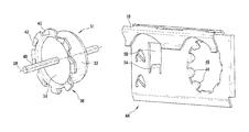
- FIG. 1 is an exploded view of the direct current motor of the invention
- FIG. 2 is a perspective view of a leadthrough capacitor designed according to the invention
- FIG. 3 is a perspective view of a ground plate for holding and contacting a leadthrough capacitor and a further connection line to the motor;
- FIG. 4 shows a fragmentary section through the stator of a direct current motor having a leadthrough arrangement with a ground plate which carries a capacitor and is locked by a bearing plate of the motor and contacted with the stator;
- FIG. 5 shows a fragmentary view of the stator of the direct current motor with the interference suppressor inserted
- FIG. 6 is a view of the interference suppressor of the motor with the connection lines to the motor brushes.
- reference numeral 10 indicates a stator of a direct current motor of the kind used for instance for heater or air conditioning blowers in motor vehicles.
- the stator 10 is embodied in two layers, with an inner housing plate 12 and an outer housing plate 14 that are permanently joined together, for instance welded together.
- recesses 16 are provided for the leadthrough of connection lines 40 and 52 , which are not shown in FIG. 1 .
- An interference suppressor 18 is placed in the region of the recesses 16 in the stator 10 and is held during mounting on a brush holder 20 . Securing the brush holder 20 with the interference suppressor 18 in the stator is done by means of a bearing plate 22 , which is permanently locked by calking in the region of protrusions 23 on the stator 10 and in so doing positions and contacts the interference suppressor 18 in the region of the recesses 16 of the stator.
- a rotor 24 with a collector 26 and a power takeoff shaft 28 is disposed in the stator 10 and drives a blower, not shown, of a motor vehicle.
- FIG. 2 in an enlarged perspective view shows a leadthrough capacitor 30 of the interference suppressor 18 , with a cylindrical, cup-shaped housing 32 .
- the term leadthrough capacitor stands here for a plurality of capacitor elements which are interconnected on a printed circuit board and embedded in a potting composition 34 .
- the potting composition may be omitted if the housing is sealed off in some other way.
- the housing 32 of the capacitor 30 has an essentially circular-annular contact flange 36 , which is disposed concentrically to the leadthrough axis 38 .
- the connection line 40 to the positive pole, not shown, of the direct voltage supply of the motor is located in the leadthrough axis 38 .
- the contact flange 36 is subdivided into individual contact portions 42 , which each have tabs, bent at an angle to the housing, for contacting the stator 10 .
- FIG. 3 shows a ground plate 44 with a first opening 46 for receiving the leadthrough capacitor 30 disposed in the connection line 40 .
- the housing 32 of the capacitor is locked, centered and contacted between identical contact tongues 48 that protrude from the circumference of the opening 46 .
- the contact tongues 48 are distributed uniformly and symmetrically to the leadthrough axis 38 of the capacitor 30 and of its housing 32 on the circumference of the opening 46 .
- Extending through a second opening 50 in the ground plate 44 is a negative line, not shown in FIG. 3 , as a second connection line of the motor, the negative line being connected to ground. This line is secured by clamping for example and electrically contacted at a holding lip 54 of the ground plate 44 .
- a second opening in the version like the opening 46 may be provided, with a further capacitor 30 .
- the ground plate 44 has a peripheral portion 56 , bent essentially in the shape of a U, with which it fits over the stator 10 and is electrically contacted with it, as will be described and explained in further detail below.
- FIG. 4 shows a fragmentary section through the stator 10 of the direct current motor and through the interference suppressor 18 . It can be seen clearly in this view how the contact portions 42 , protruding symmetrically and uniformly from the contact flange 36 , rest on the inner housing plate 12 of the stator 10 and thus establish a secure ground connection from the housing 32 of the capacitor 30 to the stator.
- the electrical contacting is effected symmetrically here and concentrically to the connection line 40 , thus optimizing the interference suppression effect.
- the contact between the ground plate 44 and the stator 10 is ensured by pressing the bearing plate 22 against the middle part of the U-shaped peripheral portion 56 of the ground plate 44 .
- an insulation mount 58 is also shown, which surrounds the connection line 40 and is fixed on the one hand in the U-shaped peripheral portion 56 of the ground plate 44 and on the other in the recesses 16 of the stator 10 .
- this insulation mount 58 By means of this insulation mount 58 , the location of the connection lines 40 and 52 ( FIG. 5 ) is defined, and the insulation of the lines in the leadthrough region is ensured, optionally including if flexible pigtail cables for the connection lines are used.
- the use of pigtail cables for connecting the carbon brushes and the use of flexible connection lines 40 , 52 also lessens the transmission of noise from the motor to the outside.
- FIG. 5 in a schematic view shows a part of the stator 10 with the inner housing plate 12 , the outer housing plate 14 , and the ground plate 44 that fits over the inner housing plate 12 with its U-shaped peripheral portion 56 .
- the connection lines 40 and 52 are shown without the insulation mount 58 .
- the alignment and positioning of the ground plate 44 is effected by means of the upward-protruding protrusion 23 of the inner housing plate 12 , which after the bearing plate 22 is placed on top and calked ensures the secure locking and contacting of the ground plate 44 at the support point 60 and of the interference suppressor 18 in the stator 10 .
- FIG. 6 in a further perspective view, shows the interference suppressor 18 with the positive connection line 40 and the negative connection line 52 , which are secured in a position and alignment in the region of the recess 16 in the stator by the insulation mount 58 .
- the connection lines 40 and 52 in this version are connected inside the motor to lead lines 68 and 70 to the brushes 72 and 74 by means of clamping bushes 64 and 66 .
- different lead line types can be selected, in particular pigtail-like lead lines 68 and 70 to the brushes and solid connection wires for the outer connection lines of the motor.
- the arrangement in FIG. 6 corresponds to the embodiment in the foregoing views.
- the expense for interference suppression of the motor can be reduced markedly, and on the other, the quality of interference suppression can be markedly improved, in particular with respect to high interference frequencies.
- the interference suppression chokes and capacitors in known interference suppressors of direct current motors can be eliminated and the effort and expense for wiring and mounting can be reduced markedly, thus lowering the total system costs for producing the motor while the interference suppression stays the same or is improved, and making it possible to meet increasingly stringent demands for electromagnetic compatibility.
- the proposed new interference suppression module can be achieved using commercially available components that are modified only slightly, making overall production and assembly less expensive, and good interference suppression can be achieved up to frequencies on the order of magnitude of 2 GHz, which occur particularly in mobile telephones.
- connection lines 40 and 52 can be attained at no additional expense.
- the design of the ground plate 44 is easily adaptable to the motor model without changing the other components of the interference suppressor 18 , and the ground plate 44 covers the recesses 16 in the stator 10 essentially without gaps and thus also improves the interference suppression with respect to interference other than line interference.
Landscapes
- Physics & Mathematics (AREA)
- Electromagnetism (AREA)
- Engineering & Computer Science (AREA)
- Power Engineering (AREA)
- Motor Or Generator Frames (AREA)
- Dc Machiner (AREA)
Abstract
Description
Claims (12)
Applications Claiming Priority (4)
| Application Number | Priority Date | Filing Date | Title |
|---|---|---|---|
| DE102007018462 | 2007-04-19 | ||
| DE102007018462.1 | 2007-04-19 | ||
| DE102007018462A DE102007018462A1 (en) | 2007-04-19 | 2007-04-19 | DC motor with a feedthrough capacitor |
| PCT/EP2008/053395 WO2008128838A1 (en) | 2007-04-19 | 2008-03-20 | Dc motor with a leadthrough capacitor |
Publications (2)
| Publication Number | Publication Date |
|---|---|
| US20100141068A1 US20100141068A1 (en) | 2010-06-10 |
| US8378538B2 true US8378538B2 (en) | 2013-02-19 |
Family
ID=39530672
Family Applications (1)
| Application Number | Title | Priority Date | Filing Date |
|---|---|---|---|
| US12/596,573 Expired - Fee Related US8378538B2 (en) | 2007-04-19 | 2008-03-20 | DC motor with a leadthrough capacitor |
Country Status (6)
| Country | Link |
|---|---|
| US (1) | US8378538B2 (en) |
| EP (1) | EP2140541A1 (en) |
| JP (1) | JP4991932B2 (en) |
| CN (1) | CN101675573B (en) |
| DE (1) | DE102007018462A1 (en) |
| WO (1) | WO2008128838A1 (en) |
Cited By (2)
| Publication number | Priority date | Publication date | Assignee | Title |
|---|---|---|---|---|
| US20120153752A1 (en) * | 2010-12-21 | 2012-06-21 | Martin Haas | Actuator apparatus and method for manufacturing an actuator apparatus |
| US10298088B2 (en) | 2013-01-26 | 2019-05-21 | Brose Fahrzeugteile Gmbh & Co. Kg, Wuerzburg | Rotary electric machine |
Families Citing this family (11)
| Publication number | Priority date | Publication date | Assignee | Title |
|---|---|---|---|---|
| DE102009000024A1 (en) * | 2009-01-05 | 2010-07-08 | Robert Bosch Gmbh | Anti-interference arrangement for an electrical machine |
| DE102009000023A1 (en) * | 2009-01-05 | 2010-07-08 | Robert Bosch Gmbh | Electrical device, in particular control unit |
| DE102009054717A1 (en) * | 2009-12-16 | 2011-06-22 | Robert Bosch GmbH, 70469 | Electric motor with noise filter |
| DE102010038446A1 (en) * | 2010-07-27 | 2012-02-02 | Robert Bosch Gmbh | Electric motor with filter element attachment |
| DE102012103928A1 (en) * | 2012-05-04 | 2013-11-07 | Pierburg Gmbh | DC motor for driving aggregates of a motor vehicle |
| CN105207416B (en) * | 2014-06-23 | 2019-03-15 | 德昌电机(深圳)有限公司 | Motor ground connecting device |
| WO2017079869A1 (en) * | 2015-11-09 | 2017-05-18 | 捷和电机制品(深圳)有限公司 | Motor and ground structure for electro-magnetic compatibility element and/or electro-static discharge element thereof |
| CN106972701A (en) * | 2016-01-14 | 2017-07-21 | 德昌电机(深圳)有限公司 | The motor of end cap device and the application end cap device |
| DE102017223065B4 (en) * | 2017-12-18 | 2021-01-14 | Bühler Motor GmbH | ELECTRIC MOTOR WITH A LEAD-THROUGH CAPACITOR |
| CN110808517B (en) * | 2019-11-21 | 2024-07-19 | 广州市博扬机械制造有限公司 | Safety current collector |
| EP4195468A1 (en) * | 2021-12-07 | 2023-06-14 | Dr. Fritz Faulhaber GmbH & Co. KG | Electric motor with interference suppression device and method for arranging an interference suppression device on an electric motor |
Citations (18)
| Publication number | Priority date | Publication date | Assignee | Title |
|---|---|---|---|---|
| US2015667A (en) * | 1931-11-23 | 1935-10-01 | Wilfred K Fleming | Radio interference eliminator |
| US4384223A (en) * | 1981-04-15 | 1983-05-17 | The Stackpole Corporation | Radio-frequency interference suppressing system for permanent magnet field motor |
| US4727274A (en) * | 1985-09-30 | 1988-02-23 | Siemens Aktiengesellschaft | Commutator motor of a closed design with an external electrical connector housing |
| US4900966A (en) * | 1987-09-11 | 1990-02-13 | Siemens Aktiengesellschaft | Protection switch for vehicle dc window motor |
| US5734212A (en) * | 1996-11-12 | 1998-03-31 | Walbro Corporation | Electric fuel pump RFI module with pre-molded housing |
| US20030007297A1 (en) * | 2000-03-23 | 2003-01-09 | Hugo Herrmann | Train relief component having an intergrated capacitor |
| DE10349301A1 (en) | 2002-10-23 | 2004-06-03 | Spectrum Control Inc. | Electromagnetic filter for feedthrough conductor, has pair of capacitors supported on one of the planar surfaces of substrate, partially surrounding feedthrough conductor |
| US6768243B1 (en) * | 1999-11-25 | 2004-07-27 | Mabuchi Motor Co., Ltd. | Small-size motor brush assembly with electrical noise suppression |
| US6982512B2 (en) * | 2004-02-09 | 2006-01-03 | Hilti Aktiengesellschaft | Interference-suppressed universal motor |
| US20060028076A1 (en) * | 2003-08-29 | 2006-02-09 | Japan Servo Co., Ltd. | Capacitor motor with terminal arrangement |
| US7018240B2 (en) * | 2004-04-22 | 2006-03-28 | Siemens Vdo Automotive Inc. | Motor assembly of X2Y RFI attenuation capacitors for motor radio frequency interference (RFI) and electromagnetic compatibility (EMC) suppression |
| DE102004046299A1 (en) | 2004-09-24 | 2006-03-30 | Robert Bosch Gmbh | DC motor especially for a motor vehicle fan has capacitive interference suppressor in connection lead at an opening in the motor housing |
| US20060113850A1 (en) | 2004-11-29 | 2006-06-01 | Tdk Corporation | Noise filter and motor |
| US20060244321A1 (en) * | 2005-04-28 | 2006-11-02 | Asmo Co., Ltd. | Motor and brush holder thereof |
| US20070170789A1 (en) * | 2006-01-25 | 2007-07-26 | Calsonic Kansei Corporation | Noise suppression structure of blower motor |
| US20070278877A1 (en) * | 2004-09-06 | 2007-12-06 | Wolfgang Winkler | Dc Motor With Supressor |
| US20080048507A1 (en) * | 2006-07-28 | 2008-02-28 | Mitsuba Corporation | Electric motor with reduction gear mechanism |
| US7843105B2 (en) * | 2005-11-30 | 2010-11-30 | Robert Bosch Gmbh | Brush holder component with ground contact plate |
Family Cites Families (2)
| Publication number | Priority date | Publication date | Assignee | Title |
|---|---|---|---|---|
| JPH0467390U (en) * | 1990-10-22 | 1992-06-15 | ||
| JP2001128415A (en) * | 1999-10-25 | 2001-05-11 | Yoshiyuki Mori | Small-sized motor |
-
2007
- 2007-04-19 DE DE102007018462A patent/DE102007018462A1/en not_active Withdrawn
-
2008
- 2008-03-20 EP EP08718106A patent/EP2140541A1/en not_active Withdrawn
- 2008-03-20 JP JP2010503442A patent/JP4991932B2/en not_active Expired - Fee Related
- 2008-03-20 CN CN2008800124929A patent/CN101675573B/en not_active Expired - Fee Related
- 2008-03-20 US US12/596,573 patent/US8378538B2/en not_active Expired - Fee Related
- 2008-03-20 WO PCT/EP2008/053395 patent/WO2008128838A1/en not_active Ceased
Patent Citations (19)
| Publication number | Priority date | Publication date | Assignee | Title |
|---|---|---|---|---|
| US2015667A (en) * | 1931-11-23 | 1935-10-01 | Wilfred K Fleming | Radio interference eliminator |
| US4384223A (en) * | 1981-04-15 | 1983-05-17 | The Stackpole Corporation | Radio-frequency interference suppressing system for permanent magnet field motor |
| US4727274A (en) * | 1985-09-30 | 1988-02-23 | Siemens Aktiengesellschaft | Commutator motor of a closed design with an external electrical connector housing |
| US4900966A (en) * | 1987-09-11 | 1990-02-13 | Siemens Aktiengesellschaft | Protection switch for vehicle dc window motor |
| US5734212A (en) * | 1996-11-12 | 1998-03-31 | Walbro Corporation | Electric fuel pump RFI module with pre-molded housing |
| US6768243B1 (en) * | 1999-11-25 | 2004-07-27 | Mabuchi Motor Co., Ltd. | Small-size motor brush assembly with electrical noise suppression |
| US20030007297A1 (en) * | 2000-03-23 | 2003-01-09 | Hugo Herrmann | Train relief component having an intergrated capacitor |
| DE10349301A1 (en) | 2002-10-23 | 2004-06-03 | Spectrum Control Inc. | Electromagnetic filter for feedthrough conductor, has pair of capacitors supported on one of the planar surfaces of substrate, partially surrounding feedthrough conductor |
| US20060028076A1 (en) * | 2003-08-29 | 2006-02-09 | Japan Servo Co., Ltd. | Capacitor motor with terminal arrangement |
| US6982512B2 (en) * | 2004-02-09 | 2006-01-03 | Hilti Aktiengesellschaft | Interference-suppressed universal motor |
| US7018240B2 (en) * | 2004-04-22 | 2006-03-28 | Siemens Vdo Automotive Inc. | Motor assembly of X2Y RFI attenuation capacitors for motor radio frequency interference (RFI) and electromagnetic compatibility (EMC) suppression |
| US20070278877A1 (en) * | 2004-09-06 | 2007-12-06 | Wolfgang Winkler | Dc Motor With Supressor |
| DE102004046299A1 (en) | 2004-09-24 | 2006-03-30 | Robert Bosch Gmbh | DC motor especially for a motor vehicle fan has capacitive interference suppressor in connection lead at an opening in the motor housing |
| US20060113850A1 (en) | 2004-11-29 | 2006-06-01 | Tdk Corporation | Noise filter and motor |
| EP1670123A2 (en) | 2004-11-29 | 2006-06-14 | TDK Corporation | Noise filter and electric motor comprising this filter |
| US20060244321A1 (en) * | 2005-04-28 | 2006-11-02 | Asmo Co., Ltd. | Motor and brush holder thereof |
| US7843105B2 (en) * | 2005-11-30 | 2010-11-30 | Robert Bosch Gmbh | Brush holder component with ground contact plate |
| US20070170789A1 (en) * | 2006-01-25 | 2007-07-26 | Calsonic Kansei Corporation | Noise suppression structure of blower motor |
| US20080048507A1 (en) * | 2006-07-28 | 2008-02-28 | Mitsuba Corporation | Electric motor with reduction gear mechanism |
Non-Patent Citations (1)
| Title |
|---|
| Translation of Foreign document DE 102004046299 A1, published 2006. * |
Cited By (4)
| Publication number | Priority date | Publication date | Assignee | Title |
|---|---|---|---|---|
| US20120153752A1 (en) * | 2010-12-21 | 2012-06-21 | Martin Haas | Actuator apparatus and method for manufacturing an actuator apparatus |
| US9788465B2 (en) * | 2010-12-21 | 2017-10-10 | Robert Bosch Gmbh | Actuator apparatus and method for manufacturing an actuator apparatus |
| US10298088B2 (en) | 2013-01-26 | 2019-05-21 | Brose Fahrzeugteile Gmbh & Co. Kg, Wuerzburg | Rotary electric machine |
| US10476345B2 (en) | 2013-01-26 | 2019-11-12 | Brose Fahrzeugteile Gmbh & Co. Kg, Wuerzburg | Rotary electric machine |
Also Published As
| Publication number | Publication date |
|---|---|
| EP2140541A1 (en) | 2010-01-06 |
| WO2008128838A1 (en) | 2008-10-30 |
| US20100141068A1 (en) | 2010-06-10 |
| DE102007018462A1 (en) | 2008-10-30 |
| CN101675573B (en) | 2012-04-18 |
| JP4991932B2 (en) | 2012-08-08 |
| JP2010525770A (en) | 2010-07-22 |
| CN101675573A (en) | 2010-03-17 |
Similar Documents
| Publication | Publication Date | Title |
|---|---|---|
| US8378538B2 (en) | DC motor with a leadthrough capacitor | |
| CN109546785B (en) | Electric motor and method for manufacturing the same | |
| EP2695794B1 (en) | Rotating electrical machine incorporating drive device | |
| US20080201928A1 (en) | Method of assembling a fan module for engine cooling applications | |
| CN104247228A (en) | DC motors for driving motor vehicle components | |
| US20110006636A1 (en) | Dc machine | |
| CN108123569B (en) | Electric motor and radiator fan module comprising an electric motor of this type | |
| US11271449B2 (en) | Electric machine with a brush-holding component and a plug module | |
| US20130088108A1 (en) | Electric motor | |
| US20200373820A1 (en) | Electric motor | |
| KR100624669B1 (en) | Motor with grounding structure to reduce radio noise | |
| JP2017518731A (en) | Brush holding device for commutator | |
| US9755486B2 (en) | Motor | |
| JP2017516453A (en) | Brush holding device for commutator | |
| JP2017519480A (en) | Brush holding device for commutator | |
| US20220006364A1 (en) | Electrical machine having an integrated temperature sensor and rotor condition capture sensor | |
| US11936275B2 (en) | Pump unit comprising a connector with sintered filter for pressure compensation | |
| CN106411041A (en) | Driving unit | |
| CN209526604U (en) | A kind of heat dissipation automobile air pump permanent magnet DC motor certainly | |
| CN104104192A (en) | Electric driver for motor vehicle | |
| JP4083353B2 (en) | Brushless motor | |
| JP2013219914A (en) | Motor | |
| EP2041857B1 (en) | A mounting structure for electric motors | |
| JP3351728B2 (en) | DC motor | |
| CN109937524B (en) | Electric machine |
Legal Events
| Date | Code | Title | Description |
|---|---|---|---|
| AS | Assignment |
Owner name: ROBERT BOSCH GMBH,GERMANY Free format text: ASSIGNMENT OF ASSIGNORS INTEREST;ASSIGNOR:SILVA, FERNANDO;REEL/FRAME:024040/0287 Effective date: 20091123 Owner name: ROBERT BOSCH GMBH, GERMANY Free format text: ASSIGNMENT OF ASSIGNORS INTEREST;ASSIGNOR:SILVA, FERNANDO;REEL/FRAME:024040/0287 Effective date: 20091123 |
|
| CC | Certificate of correction | ||
| REMI | Maintenance fee reminder mailed | ||
| LAPS | Lapse for failure to pay maintenance fees | ||
| STCH | Information on status: patent discontinuation |
Free format text: PATENT EXPIRED DUE TO NONPAYMENT OF MAINTENANCE FEES UNDER 37 CFR 1.362 |
|
| STCH | Information on status: patent discontinuation |
Free format text: PATENT EXPIRED DUE TO NONPAYMENT OF MAINTENANCE FEES UNDER 37 CFR 1.362 |
|
| FP | Lapsed due to failure to pay maintenance fee |
Effective date: 20170219 |